EP0056275B1 - Einrichtung zum Schützen einer elektrischen Leitung vor sehr steile Flanken aufweisenden Störungen - Google Patents
Einrichtung zum Schützen einer elektrischen Leitung vor sehr steile Flanken aufweisenden Störungen Download PDFInfo
- Publication number
- EP0056275B1 EP0056275B1 EP82100157A EP82100157A EP0056275B1 EP 0056275 B1 EP0056275 B1 EP 0056275B1 EP 82100157 A EP82100157 A EP 82100157A EP 82100157 A EP82100157 A EP 82100157A EP 0056275 B1 EP0056275 B1 EP 0056275B1
- Authority
- EP
- European Patent Office
- Prior art keywords
- stage
- conductor
- box
- stages
- spark
- Prior art date
- Legal status (The legal status is an assumption and is not a legal conclusion. Google has not performed a legal analysis and makes no representation as to the accuracy of the status listed.)
- Expired
Links
- 239000004020 conductor Substances 0.000 claims description 25
- 239000002184 metal Substances 0.000 claims description 8
- 229910052751 metal Inorganic materials 0.000 claims description 8
- 238000011144 upstream manufacturing Methods 0.000 claims description 7
- 239000007787 solid Substances 0.000 claims description 4
- 229910000831 Steel Inorganic materials 0.000 claims description 3
- 239000010959 steel Substances 0.000 claims description 3
- 230000007423 decrease Effects 0.000 claims description 2
- RYGMFSIKBFXOCR-UHFFFAOYSA-N Copper Chemical compound [Cu] RYGMFSIKBFXOCR-UHFFFAOYSA-N 0.000 description 3
- 229910052802 copper Inorganic materials 0.000 description 3
- 239000010949 copper Substances 0.000 description 3
- 239000012212 insulator Substances 0.000 description 3
- PNEYBMLMFCGWSK-UHFFFAOYSA-N aluminium oxide Inorganic materials [O-2].[O-2].[O-2].[Al+3].[Al+3] PNEYBMLMFCGWSK-UHFFFAOYSA-N 0.000 description 2
- 238000004880 explosion Methods 0.000 description 2
- 239000004698 Polyethylene Substances 0.000 description 1
- 229910018503 SF6 Inorganic materials 0.000 description 1
- 240000008042 Zea mays Species 0.000 description 1
- 239000006096 absorbing agent Substances 0.000 description 1
- 230000005540 biological transmission Effects 0.000 description 1
- 239000003990 capacitor Substances 0.000 description 1
- 239000006229 carbon black Substances 0.000 description 1
- 230000000694 effects Effects 0.000 description 1
- 230000005288 electromagnetic effect Effects 0.000 description 1
- 235000021183 entrée Nutrition 0.000 description 1
- 239000011521 glass Substances 0.000 description 1
- 239000000463 material Substances 0.000 description 1
- 238000005259 measurement Methods 0.000 description 1
- 230000000116 mitigating effect Effects 0.000 description 1
- 230000007935 neutral effect Effects 0.000 description 1
- 239000004033 plastic Substances 0.000 description 1
- 229920003023 plastic Polymers 0.000 description 1
- -1 polyethylene Polymers 0.000 description 1
- 229920000573 polyethylene Polymers 0.000 description 1
- 230000001681 protective effect Effects 0.000 description 1
- 238000007789 sealing Methods 0.000 description 1
- SFZCNBIFKDRMGX-UHFFFAOYSA-N sulfur hexafluoride Chemical compound FS(F)(F)(F)(F)F SFZCNBIFKDRMGX-UHFFFAOYSA-N 0.000 description 1
- 229960000909 sulfur hexafluoride Drugs 0.000 description 1
- 230000003313 weakening effect Effects 0.000 description 1
Images
Classifications
-
- H—ELECTRICITY
- H02—GENERATION; CONVERSION OR DISTRIBUTION OF ELECTRIC POWER
- H02H—EMERGENCY PROTECTIVE CIRCUIT ARRANGEMENTS
- H02H9/00—Emergency protective circuit arrangements for limiting excess current or voltage without disconnection
- H02H9/04—Emergency protective circuit arrangements for limiting excess current or voltage without disconnection responsive to excess voltage
- H02H9/06—Emergency protective circuit arrangements for limiting excess current or voltage without disconnection responsive to excess voltage using spark-gap arresters
Definitions
- the present invention relates to a device for protecting a low-voltage power line against voltage disturbances with a very steep front, comprising a box with several stages in series arranged in series and upstream with respect to the line to be protected, at least certain stages of the box containing limiting components.
- Devices of this kind have already been proposed, in particular for the protection of low voltage power lines, of energy, of measurement or of transmission, against the electromagnetic effects of nuclear explosions.
- they only allow the power line to be protected against pulses with a voltage rise speed of at most 1 kV / nanosecond.
- high-powered nuclear explosions can induce disturbances of a rate of rise of the order of ten kilovolts per nanosecond or more.
- the spark gaps of these devices risk not starting when they are subjected to disturbances of such a short rise time, or starting only at very high voltages, and therefore no longer play their protective role.
- the purpose of the device according to the invention is to provide effective protection of low-voltage electrical lines against disturbances with very steep fronts with a rise speed of the order of one or more tens of kilovolts per nanosecond, corresponding at an energy level of the order of hundreds of kilojoules and at permanent powers of the order of a hundred kW with very close time intervals.
- This device has a high shunt impedance and leaves residual disturbances of only a few hundred volts.
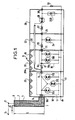
- the device according to the invention is characterized in that it comprises, upstream of the cabinet, a portion of electrical conductor in series with respect to the figure to be protected and surrounded by a metal tube closed at its ends by insulating and separate windows conductor by a solid or gaseous insulator, the conductor portion and the tube constituting a coaxial line reducing the slope of the disturbances before they enter the cabinet, each stage of the cabinet then gradually mitigating these disturbances.
- the disturbing pulse as well as the normal operating voltage, arrive, in a disturbed area, from a terminal 1 to the input terminal 2 of the device for protecting the phase in question.
- the conductor 3 is isolated from the tube 4 by an insulator 7, which can be gaseous or solid; the insulator is gaseous (SF 6) when the voltage of the incident disturbance reaches several hundred kV; it is solid (for example polyethylene or alumina) for peak voltages less than 200 kV.
- a conduit 8 allows the introduction of sulfur hexafluoride into the tube 4.
- the length of conductor 3 and of tube 4, which constitute a coaxial line, has a value L such that the slope P o of the incident disturbing pulse drops to a value P 1 at the output of conductor 3.
- the slope P 1 is also a function of the load impedance of the operating circuit. For example, for a slope Po of 20 kV / ns, the slope P 1 drops to 3 to 5 kV / ns for a length of 2 m.
- the slope disturbing pulse P enters the first stage 10 of the metal box 9 by an insulating passage 10A.
- Spark gaps 12A, 12B and 12C are arranged in a shunt in a symmetrical manner, between the phase conductor and the earth, constituted by a copper grid floor 13; they are enclosed in a copper box 11, itself disposed in the steel compartment 10, so as to shield both the spark gaps electrically and magnetically.
- the number of these spark gaps depends on the energy of the incident pulse, and could be reduced if it was weaker.
- spark gaps When several spark gaps are in parallel, and subjected to a steep front voltage, one of the spark gaps strikes first, a very short instant before the others. The discharge voltage of this spark gap in turn triggers a second spark gap and so on.
- the phase conductor then passes through an insulating crossing 14 in a second shielded compartment 15.
- the center of the disturbing pulse is reduced at the entry into this compartment to approximately 1 kV / 10 ns, and the peak voltage to 10 to 20 kV.
- a self-inductance 16 which can reach a value of 30 to 50 microhenrys then, after an insulating crossing 17, a box 18 shielded like the box 11, where there are two spark gaps 19A and 19B which are arranged in shunt and symmetrically between the phase conductor and the earth.
- absorbers 20 of the high frequency energy which have for their object to damp the cavities which they constitute, and formed for example from a plastic material loaded with carbon black.
- a third shielded compartment 22 is then reached.
- the slope of the pulse is reduced at the input thereof to approximately 1 kV / 100 ns and the peak voltage to 3 to 5 kV.
- a self-inductance 23 with a value of 10 to 20 microhenrys, then a spark gap 24 in shunt.
- the spark gaps 12A, 12B, 12C, 19A, 19B and 24 are spark gaps of the ignition type under very fast wave fronts.
- the spark gaps 19A, 19B preferably prime for a voltage lower than 12A, 12B, 12C as well as the spark gap 24 preferably ignites for a voltage lower than 19A and 19B.
- An insulating bushing 25 then gives access to a fourth shielded compartment 26.
- the slope of the pulse is reduced at its entry to approximately 1 kV / microsecond and the peak voltage to approximately 1 kV
- the thyristor 28 is normally conductive and interrupts the circuit during the passage of the disturbance under the effect of the signal transmitted by the coaxial cable.
- a capacitor 29B prevents a sudden drop in voltage.
- An insulating bushing 30 finally constitutes the output terminal of the protection device.
- the slope of the disturbance is reduced to around 1 kV / 10 microseconds and the peak voltage to 100-200 V.
- the payload is represented here by a resistor 31 arranged between the output terminal and the earth. She can be locked in an armored structure.
- the impedance between the phase conductor and the neutral can have a value greater than 0.1 Megohm.
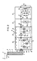
- the protection device shown in FIG. 2 is identical to that of FIG. 1 with regard to the input coaxial line and the first two spark gap stages, and these parts will not be described again.
- the spark gap is replaced by a variable resistor sensitive to voltage 24A, the resistance of which increases when the applied voltage rises. This plays the same role as the spark gap 24, but can withstand a higher intensity.
- the thyristor 28 is replaced by Zener or trans-Zorb diodes in parallel 26A, themselves in parallel with a filter bandpass 32, capacitance 33 and inductor 34.
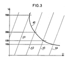
- FIG. 3 represents the curve 40 giving the ignition voltages V of the successive stages as a function of their position L1 in the device of FIGS. 1 or 2, the lines 41, 42, 43, 44 corresponding to determined slopes of the incident disturbance .
- starting voltages of 7 kV, 2 kV, 1200 V. and 1100 volts are obtained for slopes of 1 kV / ns, 1 kV / 10 ns, 1 kV / 100 ns and 1 kV / ps. It is therefore possible to determine, as a function of the slope of the incident disturbance and of its weakening in the successive stages, the voltage for which the spark gaps will strike.
- the number of spark gaps per stage can be modified and the earthing of the boxes can be carried out by a copper bar extending through them.
Landscapes
- Emergency Protection Circuit Devices (AREA)
- Rectifiers (AREA)
- Testing Relating To Insulation (AREA)
Claims (8)
Applications Claiming Priority (2)
| Application Number | Priority Date | Filing Date | Title |
|---|---|---|---|
| FR8100538A FR2498023A1 (fr) | 1981-01-14 | 1981-01-14 | Dispositif de protection d'une ligne electrique contre des perturbations a front tres raide |
| FR8100538 | 1981-01-14 |
Publications (2)
| Publication Number | Publication Date |
|---|---|
| EP0056275A1 EP0056275A1 (de) | 1982-07-21 |
| EP0056275B1 true EP0056275B1 (de) | 1985-12-18 |
Family
ID=9254111
Family Applications (1)
| Application Number | Title | Priority Date | Filing Date |
|---|---|---|---|
| EP82100157A Expired EP0056275B1 (de) | 1981-01-14 | 1982-01-12 | Einrichtung zum Schützen einer elektrischen Leitung vor sehr steile Flanken aufweisenden Störungen |
Country Status (6)
| Country | Link |
|---|---|
| US (1) | US4463406A (de) |
| EP (1) | EP0056275B1 (de) |
| JP (1) | JPS57142127A (de) |
| CA (1) | CA1184594A (de) |
| DE (1) | DE3267947D1 (de) |
| FR (1) | FR2498023A1 (de) |
Families Citing this family (19)
| Publication number | Priority date | Publication date | Assignee | Title |
|---|---|---|---|---|
| DE3402581A1 (de) * | 1984-01-26 | 1985-08-01 | Philips Patentverwaltung Gmbh, 2000 Hamburg | Anordnung zum unterdruecken von ueberspannungsspitzen |
| US4563720A (en) * | 1984-04-17 | 1986-01-07 | General Semiconductor Industries, Inc. | Hybrid AC line transient suppressor |
| DE3565034D1 (en) * | 1984-04-30 | 1988-10-20 | Siemens Ag | Rough overvoltage protection circuit for a repeater or regenerator |
| DE3425296A1 (de) * | 1984-07-10 | 1986-01-16 | Wolf-Dieter Dr.-Ing. 4600 Dortmund Oels | Vorrichtung zum schutz gegen ueberspannungen mit einer grobschutz- und einer feinschutzeinrichtung |
| US5428494A (en) * | 1984-10-24 | 1995-06-27 | Omtronics Corp. | Power line protector, monitor and management system |
| NL8502163A (nl) * | 1985-07-31 | 1987-02-16 | Nederlanden Staat | Inrichting voor het beveiligen van asymmetrische electrische transmissiecircuits tegen overspanning o.a. tengevolge van electromagnetische pulsen met zeer hoge flanksteilheid. |
| EP0250919B1 (de) * | 1986-06-20 | 1990-09-05 | Siemens Aktiengesellschaft | Netzleitungsfilter für 3-Phasen-Systeme |
| US4807081A (en) * | 1986-09-05 | 1989-02-21 | Raychem Limited | Circuit protection arrangement |
| DE3864328D1 (de) * | 1987-06-16 | 1991-09-26 | Commissariat Energie Atomique | Schutzeinrichtung fuer eine elektronische einrichtung gegen starke elektromagnetische impulse, insbesondere durch blitzschlag hervorgerufen. |
| FR2616979B1 (fr) * | 1987-06-16 | 1993-05-28 | Aerospatiale | Dispositif de protection d'un equipement electronique contre les fortes impulsions electromagnetiques, notamment dues a la foudre |
| FR2616978B1 (fr) * | 1987-06-16 | 1989-08-18 | Aerospatiale | Dispositif de protection d'un equipement electronique contre les fortes impulsions electromagnetiques, notamment dues a la foudre |
| US4901183A (en) * | 1988-08-29 | 1990-02-13 | World Products, Inc. | Surge protection device |
| US4870534A (en) * | 1988-09-02 | 1989-09-26 | Harford Jack R | Power line surge suppressor |
| FR2665031B1 (fr) * | 1990-07-23 | 1992-12-11 | Cordier Jacques | Attenuateur de surtensions et de surintensites equilibre. |
| JP3492042B2 (ja) * | 1995-08-31 | 2004-02-03 | 関西電力株式会社 | 高調波抑制型電力線瞬時切替装置 |
| US5856740A (en) * | 1997-05-09 | 1999-01-05 | Emerson Electric Co. | Shunt voltage regulator with a variable load unit |
| US8625247B2 (en) * | 2007-10-03 | 2014-01-07 | Huber + Suhner Ag | Protective circuit for the input-side protection of an electronic device operating in the maximum frequency range |
| US20180048145A1 (en) * | 2016-08-12 | 2018-02-15 | Hamilton Sundstrand Corporation | Transient voltage protection circuits |
| SG11202104590SA (en) | 2018-11-20 | 2021-06-29 | Lubrizol Corp | Graphene production and composition |
Family Cites Families (3)
| Publication number | Priority date | Publication date | Assignee | Title |
|---|---|---|---|---|
| US3274447A (en) * | 1963-03-14 | 1966-09-20 | Noel R Nelson | Coaxial cable lightning arrester |
| CH555097A (de) * | 1972-09-27 | 1974-10-15 | Siemens Ag | Metallgekapselte hochspannungsanlage mit einem ueberspannungsableiter. |
| US3795840A (en) * | 1972-11-29 | 1974-03-05 | Nasa | Overvoltage protection network |
-
1981
- 1981-01-14 FR FR8100538A patent/FR2498023A1/fr active Granted
-
1982
- 1982-01-12 EP EP82100157A patent/EP0056275B1/de not_active Expired
- 1982-01-12 DE DE8282100157T patent/DE3267947D1/de not_active Expired
- 1982-01-13 CA CA000394093A patent/CA1184594A/fr not_active Expired
- 1982-01-13 US US06/339,192 patent/US4463406A/en not_active Expired - Fee Related
- 1982-01-13 JP JP57003975A patent/JPS57142127A/ja active Granted
Also Published As
| Publication number | Publication date |
|---|---|
| EP0056275A1 (de) | 1982-07-21 |
| US4463406A (en) | 1984-07-31 |
| CA1184594A (fr) | 1985-03-26 |
| JPH0247180B2 (de) | 1990-10-18 |
| FR2498023B1 (de) | 1983-02-11 |
| JPS57142127A (en) | 1982-09-02 |
| DE3267947D1 (en) | 1986-01-30 |
| FR2498023A1 (fr) | 1982-07-16 |
Similar Documents
| Publication | Publication Date | Title |
|---|---|---|
| EP0056275B1 (de) | Einrichtung zum Schützen einer elektrischen Leitung vor sehr steile Flanken aufweisenden Störungen | |
| EP0205149B1 (de) | Schutzeinrichtung für eine elektrische Energieleitung gegen hohe, transiente Überspannungen | |
| EP1281227B1 (de) | Überspannungsschutzelement | |
| EP0192000B1 (de) | Blitzableiter mit periodischer Corona-Stossentladung | |
| US4816611A (en) | Carrier system for lightning current | |
| EP1709717B1 (de) | Einrichtung zum schutz vor spannungsspitzen mit parallelen gleichzeitig ausgelösten luftspalten | |
| EP0296054B1 (de) | Schutzeinrichtung für eine elektronische Einrichtung gegen starke elektromagnetische Impulse, insbesondere durch Blitzschlag hervorgerufen | |
| EP0228321B1 (de) | Blitzschutzverfahren, Mittel zur Ausführung dieses Verfahrens und Blitzschutzanlage | |
| FR2501931A1 (fr) | Dispositif de protection contre les impulsions electromagnetiques a front raide | |
| EP1870977B1 (de) | Vorrichtung zum Schutz gegen Überspannungen, die mit mehreren, in Reihe geschalteten Funkenstrecken mit simultaner Auslösung verbunden ist, und entsprechende Verfahren | |
| FR2576471A1 (fr) | Dispositif de protection d'une ligne coaxiale a haute frequence contre des impulsions parasites | |
| EP0060756B1 (de) | Ionisierender Blitzableiter mit Corona-Effekt | |
| FR2563058A1 (fr) | Dispositif de protection d'un equipement electrique relie a un reseau basse tension contre les fortes impulsions electromagnetiques, notamment dues a la foudre | |
| FR2716307A1 (fr) | Dispositif pour la protection contre les perturbations électromagnétiques conduites impulsionnelles de grande amplitude, avec extinction d'un éclateur par un dispositif de dérivation à semiconducteur. | |
| EP1628378B1 (de) | Überspannungsschutzvorrichtung einschliesslich paralleler Funkenstrecken | |
| WO1993015542A1 (fr) | Attenuateur de surtension et de courant de surcharge | |
| EP0189692B1 (de) | Generator für synchrone starke Stromimpulse an parallelen Ausgängen | |
| SE513745C2 (sv) | Anordning för alstring av elektriska fyrkantspulser | |
| KR101180019B1 (ko) | 고고도 전자기파 필터(hemp)용 바이패스모듈 | |
| FR2629263A1 (fr) | Dispositif de protection pour appareil electrique a moyenne tension | |
| EP1628377A1 (de) | Schutzvorrichtung für elektrische Anlagen gegen Überspannungen einschliesslich einer Funkenstrecke mit Zündschaltung | |
| FR2650078A1 (fr) | Systeme de detection de defaut d'isolement d'une ligne de distribution d'energie electrique moyenne tension | |
| EP0323379A1 (de) | Überspannungsbegrenzer mit doppeltem Effekt | |
| WO2018197481A1 (fr) | Cable electrique pour cablage de parafoudre | |
| BE651660A (de) |
Legal Events
| Date | Code | Title | Description |
|---|---|---|---|
| PUAI | Public reference made under article 153(3) epc to a published international application that has entered the european phase |
Free format text: ORIGINAL CODE: 0009012 |
|
| AK | Designated contracting states |
Designated state(s): BE CH DE FR GB IT NL SE |
|
| 17P | Request for examination filed |
Effective date: 19821221 |
|
| GRAA | (expected) grant |
Free format text: ORIGINAL CODE: 0009210 |
|
| AK | Designated contracting states |
Designated state(s): BE CH DE FR GB IT LI NL SE |
|
| ITF | It: translation for a ep patent filed | ||
| REF | Corresponds to: |
Ref document number: 3267947 Country of ref document: DE Date of ref document: 19860130 |
|
| PLBE | No opposition filed within time limit |
Free format text: ORIGINAL CODE: 0009261 |
|
| STAA | Information on the status of an ep patent application or granted ep patent |
Free format text: STATUS: NO OPPOSITION FILED WITHIN TIME LIMIT |
|
| 26N | No opposition filed | ||
| PGFP | Annual fee paid to national office [announced via postgrant information from national office to epo] |
Ref country code: NL Payment date: 19890131 Year of fee payment: 10 |
|
| PGFP | Annual fee paid to national office [announced via postgrant information from national office to epo] |
Ref country code: FR Payment date: 19891218 Year of fee payment: 9 |
|
| PGFP | Annual fee paid to national office [announced via postgrant information from national office to epo] |
Ref country code: GB Payment date: 19891231 Year of fee payment: 9 |
|
| PGFP | Annual fee paid to national office [announced via postgrant information from national office to epo] |
Ref country code: SE Payment date: 19900112 Year of fee payment: 9 |
|
| PGFP | Annual fee paid to national office [announced via postgrant information from national office to epo] |
Ref country code: CH Payment date: 19900115 Year of fee payment: 9 |
|
| ITTA | It: last paid annual fee | ||
| PGFP | Annual fee paid to national office [announced via postgrant information from national office to epo] |
Ref country code: BE Payment date: 19900208 Year of fee payment: 9 |
|
| PGFP | Annual fee paid to national office [announced via postgrant information from national office to epo] |
Ref country code: DE Payment date: 19900222 Year of fee payment: 9 |
|
| PG25 | Lapsed in a contracting state [announced via postgrant information from national office to epo] |
Ref country code: GB Effective date: 19910112 |
|
| PG25 | Lapsed in a contracting state [announced via postgrant information from national office to epo] |
Ref country code: SE Effective date: 19910113 |
|
| PG25 | Lapsed in a contracting state [announced via postgrant information from national office to epo] |
Ref country code: CH Effective date: 19910131 Ref country code: LI Effective date: 19910131 Ref country code: BE Effective date: 19910131 |
|
| PG25 | Lapsed in a contracting state [announced via postgrant information from national office to epo] |
Ref country code: NL Effective date: 19910801 |
|
| GBPC | Gb: european patent ceased through non-payment of renewal fee | ||
| NLV4 | Nl: lapsed or anulled due to non-payment of the annual fee | ||
| PG25 | Lapsed in a contracting state [announced via postgrant information from national office to epo] |
Ref country code: FR Effective date: 19910930 |
|
| REG | Reference to a national code |
Ref country code: CH Ref legal event code: PL |
|
| PG25 | Lapsed in a contracting state [announced via postgrant information from national office to epo] |
Ref country code: DE Effective date: 19911001 |
|
| REG | Reference to a national code |
Ref country code: FR Ref legal event code: ST |
|
| EUG | Se: european patent has lapsed |
Ref document number: 82100157.5 Effective date: 19910910 |