EP0055965B1 - Process and device for the binarization of a pattern - Google Patents
Process and device for the binarization of a pattern Download PDFInfo
- Publication number
- EP0055965B1 EP0055965B1 EP81402085A EP81402085A EP0055965B1 EP 0055965 B1 EP0055965 B1 EP 0055965B1 EP 81402085 A EP81402085 A EP 81402085A EP 81402085 A EP81402085 A EP 81402085A EP 0055965 B1 EP0055965 B1 EP 0055965B1
- Authority
- EP
- European Patent Office
- Prior art keywords
- difference
- signs
- positive
- negative
- points
- Prior art date
- Legal status (The legal status is an assumption and is not a legal conclusion. Google has not performed a legal analysis and makes no representation as to the accuracy of the status listed.)
- Expired
Links
Images


Classifications
-
- G—PHYSICS
- G06—COMPUTING OR CALCULATING; COUNTING
- G06V—IMAGE OR VIDEO RECOGNITION OR UNDERSTANDING
- G06V10/00—Arrangements for image or video recognition or understanding
- G06V10/20—Image preprocessing
- G06V10/28—Quantising the image, e.g. histogram thresholding for discrimination between background and foreground patterns
Definitions
- the invention relates to a process and a device for the binarization of a pattern wherein successively scanned areas of the pattern are given a dark or bright quality from a signal indicative of the intensity values of spatially distributed discrete points of the pattern.
- a signal indicative of the intensity values of spatially distributed discrete points of the pattern is specially made here to patterns including contrasted areas differing by the light intensity, in a video signal, it should be understood that the expressions used are meant to cover any other kind of contrast between opposite qualities, such as black and white, colored and not colored, transparent and not transparent, conductive and not conductive.
- OCR optical character readers
- the inked areas correspond to logical 1.
- the areas are composed of elementary sampled points, such as may be obtained by the use of an array of photodetectors, where the size of the elementary sampled area is chosen with respect to the smallest dimensions of objects of interest for the OCR system. This explains the requirement on the part of the majority of OCR equipment suppliers for very tight tolerances on the print contrast signal (PCS) of documents intended to be read by their equipment.
- PCS print contrast signal
- a simple and often cited form of laplacean uses a central disk with weight +1 and a concentric ring with weight -1. However this simple form cannot be used with practical scanners containing arrays of photodetectors, yielding a discrete raster.
- the simplest equivalent operator well known in the literature, is based on a 3x3 square of elementary sampled areas. The central sampled area is given the weight of +8, while each of the peripheral sampled areas, eight in number, is given the weight -1. Again the total weight is zero; such a scheme is called a finite-difference approximation to the laplacean operator.
- the video values sampled at each of the elementary areas is summed with the corresponding weight and the result compared to a negative threshold. If the result is positive, the value 0 is assigned to the central elementary area, if negative, then the value 1.
- the finite-difference approximation to the laplacean need not be limited to 3x3, but may have arbitrary numbers of elementary sampled areas in any approximately circular arrangement, as long as the weights are symetrically arranged with respect of the axes of symmetry and the central sampled area. If D is the diameter of such an operator, measured in the number of elementary sampled areas across this diameter, the maximum width of inked area that can be correctly detected without hollowing will always be (D-1). The extent of the configuration must obviously be compatible with the widest object to be detected. On the other hand, if the shapes of small objects are to be faithfully reproduced, the size of the elementary sampled area must be smaller than the least dimension of such small objects.
- a further cause of difficulty with the laplacean is more fundamental and has up to now prevented its general use for solution of the binarization problem in.
- OCR devices it has a tendency to magnify slight accidental contrast variations, such as are due to microscopic defects in printing or lack of uniformity of background of the medium bearing the printing or writing, resulting in undue changes in the shapes of the boundaries of such objects after binarization, a phenomenon referred to in the art as "noise amplification".
- American patent 3 805 239 discloses a binarization circuit succeeding in recognizing the shapes of printed symbols, based on the laplacean mathematical models.
- Such circuit comprises a matrix pattern such as 3x3 matrix pattern consisting of nine picture elements in total, eight of which are arranged around the central one, and determining the differences between the gray level of the central picture element and those of the eight surrounding picture elements to obtain a sum of these differences.
- a threshold value is used as gray level of maximum value.
- the object of the present invention to supply simple means for binarizing an image based on local contrast, simpler than known systems, while avoiding the phenomenon of noise amplification.
- the invention will be simple enough to implement that extensive configurations will not require excessive material for their construction and implementation.
- the operating principle of the present invention as defined by the claims consists, for each elementary area in registering the intensity values of points distributed in at least two concentric rings within at least one sector centered on said elementary area, determining a number of contrast values each equal to the difference of registered intensity values between a point of an inner ring and a point of an outer ring, assigning a positive and negative difference sign to respectively the positive and negative contrast values showing an absolute value higher than a predetermined contrast threshold, counting separately said positive and negative difference signs, and assigning a light or dark quality to said area respectively when said counted signs contain a predominant number of positive or negative signs by more than a predetermined minimum.
- the points the intensity values of which are used are selected from the elementary areas around the central one which is being evaluated, and they are regularly distributed with circular symmetry around the central point.
- the number of rings where they are located, at different radial distances from the central point, is most usually two or three, and the central point itself may be one such ring.
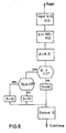
- the video input to the binarizer is obtained sequentially from a scanning head, where successive samples are digitised (converted to digital values) with a number of bits compatible with the signal quality and its signal/ noise ratio.
- the current value of the digital video is applied to one input of a difference circuit 1 and to the input to a digital delay line 2 whose outputs are multiplexed to the other input of the difference circuit by a multiplexer 3.
- the various outputs of the multiplexed difference circuit are assembled into a single word by the register 4 and input to a digital delay line 5.
- the digital delay line 5 has a large number of output positions, corresponding to individual bits of the input words, delayed by various amounts; all of these bits are input to the dual bit counting circuit 6, which counts separately the numbers of positive and negative differences that have been transmitted to it from the digital delay line 5. The two counts are applied to two inputs to the evaluation circuit 7, which assigns the value 0 or 1 to a certain elementary area, depending on whether the result of evaluation indicates that it is to be considered white or black.
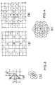
- Figure 2 shows three sets of arrows in different configurations at (a), (b) and (c).
- the sets of arrows from symmetrical patterns about the x-and y- axes at 45 degrees, passing through the elementary sampled area 0, taken as origin, in (a) and (b), or the three axes at 120 degrees in (c).
- Each of these arrows corresponds to one pair of values whose difference is taken in the direction indicated by the arrow: the value at the arrowhead is subtracted from the value at the foot of the arrow.
- the device called difference circuit 1 on Figure 1 carries out the following operations: for each arrow it takes the corresponding difference; the absolute value of the difference is compared to a threshold u; if the absolute value of the difference exceeds the threshold, the sign of the difference is encoded by two bits and input to a particular position of the register 4.
- the same elementary area may appear in two or more differences, depending on the configuration of arrows.
- the arrows are here used only to represent graphically the positions of the elementary sampled areas whose differences are taken, two-by-two.
- the configurations shown in Figure 2 are for purposes of illustration only, and that other configurations may be found to be advantageous in particular cases.
- the difference module must compute four differences: where V(X) represents the video value at the position X. This can be done by a single adder- subtractor module to which the value V(0) is applied constantly to the first input, and the values V(A), V(B), V(C), V(D) are applied successively to the other (subtracting) input from a shift register delay line 2 over the multiplexer 3. If we use the notation V(i,j) to represent the various values V(X), where i,j are the row and column coordinates of the position X, we can rewrite (1) in the following form, where we take the position of 0 as i,j and the other positions are labelled by their offsets from that position:
- each of these differences is put into the form of absolute value and sign; if the absolute value exceeds the threshold u, the sign is output to a particular position in the output register 4 which can take the convenient form of a parallel - in - parallel - out - serial - shift register.
- the value of u is to be selected exclusively from considerations of signal/noise ratio. When the video signal has been digitised to six bits, for example, and it is known that the errors and variations of print contrast do not exceed, say 10% of maximum brightness to be observed, u can usefully be set to 1/8 of full scale, i.e.;, 7 or 8. It will be appreciated that this value is given for sake of illustration only, and that the concrete value to be selected in each case will depend on the details of the design and application.
- the next operation is to count the + and - difference signs corresponding to the full configuration represented in Figure 2(a). Assume that the scan proceeds by columns, the columns succeeding each other from left to right, in the well known manner for generating OCR rasters.
- the arrows 11, 12, 13, 14 correspond to the standard configuration of Figure 3(a). However we cannot use them at the time that elementary area 0 is being computed by the difference circuit 1, since the differences corresponding to arrows 15 through 19 and 116 through 120 have not yet been computed, as the corresponding elementary sampled areas have not yet been scanned.
- the earliest time at which all the required differences for the elementary area 0 are available is when the area labelled 201 has arrived.
- the total number of difference signs is 20, each with the value + or -. Assigning a unit value to each sign, the twenty signs can be obtained at various outputs along the digital delay line 5 and applied to the positive and negative inputs, respectively, of two circuits for counting the number of each kind, in the bit-counting circuit 6.
- the sign inversion s is easily obtained by wiring the +1 bit to the -1 input to the counter and vice versa.
- the difference signs can be put into two shift registers, whose length are equal to the total number of differences in the configuration; they are then shifted out rapidly to the inputs to two binary counter circuits. At the completion of the operation each counter will contain the numbers of bits equal to 1 that were applied to the inputs.
- This operation uses a constant amount of hardware (except for the length of shift register, and this can be multiplexed), but the circuit speeds required obviously increase as the number of differences increases-the entire operation must be completed within the time of one sampling operation of the photodetector array.
- a combinational circuit can be designed, using either standard logic modules or custom designed circuits if quantities justify, that produce the required result by parallel logic; the number of inputs is equal to the number of differences to be counted. Such a design is extremely fast, but its complexity increases approximately as the square of the number of inputs.
- a third solution would be to multiplex the difference signs into a certain number of words of a fixed number of bits, the length of word being chosen with respect to economical read-only memory modules (ROM); the output words from the ROM can obviously be the binary number corresponding to the number of bits equal to 1 in each possible input word; the output binary numbers are added in an accumulator.
- This design is intermediate in speed between the counter and the combinational circuits described above, and has a fixed volume of material, regardless of the number of difference signs to be counted.
- the final result of the bit counting operations is two binary numbers, ⁇ (+), ⁇ (), representing respectively the numbers of positive and negative differences that have exceeded the threshold u.
- the final step in the binarization is the decision concerning the binary value (0 or 1) to be assigned to the elementary area 0. This may be effected in various ways. For example, the two binary numbers ⁇ (+) and Z(-) can be concatenated and used as the address to a ROM containing a 1-bit table corresponding to the decision 1 or 0 to be taken for each possible pair of counts. This design will allow an arbitrary experimental relation between the counts and the final evaluation.
- An alternative solution is to use numerical comparators to compare the number of positive to the number of negative difference signs, and to compare the number of negative signs to some fixed threshold by the following relations, for example; which have the effect of requiring that the area 0 be confirmed by no less than k differences indicating that 0 is darker than its environment, on the one hand, and that the number of differences indicating that it is darker be at least equal to the number indicating that it is lighter.
- Other, more complex laws may suggest themselves to the designer; however, complexity is generally a drawback and the ROM design first suggested above is usually preferred.
- the value of k is chosen from considerations of a minimum dimension expected of the observed configuration.
- the use of the difference sign instead of the actual video value constitutes one source of economy and simplicity of the present binarizer as compared with the laplacean operator.
- the configurations indicated here occupy much larger areas in terms of the number of elementary sampled areas than are usually used in the finite-difference laplacean, which would render the exact computation exceedingly complex as compared with the present invention.
- the difference between the laplacean operator as such and the present device is more fundamental.
- the use of the threshold u suppresses certain sources of disturbance that are magnified by the true laplacean operator, rendering the use of the latter impractical for the type of binarizer here considered. This consideration will serve as the guide for the choice of the value of the threshold u.
- the difference signs that pass the threshold u should correspond to true contrast differences, however slight, but not to accidental differences ("noise") within the background or within the inked area.
- the best value of u would be one that suppressed the majority of noise differences, but not all, as the difference counting and decision process will also play a role in suppressing isolated noise differences.
- the device according to the invention can be designed by consideration of the laplacean operator that would be suitable for a given application; from the distribution of weights in the finite-difference laplacean the configuration of differences can be found; the rest of the design process will be evident to the specialist from the above description of the functioning of the system.
Landscapes
- Engineering & Computer Science (AREA)
- Physics & Mathematics (AREA)
- General Physics & Mathematics (AREA)
- Multimedia (AREA)
- Theoretical Computer Science (AREA)
- Image Processing (AREA)
- Image Analysis (AREA)
- Character Input (AREA)
- Image Input (AREA)
Priority Applications (1)
| Application Number | Priority Date | Filing Date | Title |
|---|---|---|---|
| AT81402085T ATE41833T1 (de) | 1981-01-05 | 1981-12-28 | Verfahren und geraet zur umwandlung eines musters in eine binaere form. |
Applications Claiming Priority (2)
| Application Number | Priority Date | Filing Date | Title |
|---|---|---|---|
| GB8100094 | 1981-01-05 | ||
| GB8100094 | 1981-01-05 |
Publications (3)
| Publication Number | Publication Date |
|---|---|
| EP0055965A2 EP0055965A2 (en) | 1982-07-14 |
| EP0055965A3 EP0055965A3 (en) | 1984-08-01 |
| EP0055965B1 true EP0055965B1 (en) | 1989-03-29 |
Family
ID=10518780
Family Applications (1)
| Application Number | Title | Priority Date | Filing Date |
|---|---|---|---|
| EP81402085A Expired EP0055965B1 (en) | 1981-01-05 | 1981-12-28 | Process and device for the binarization of a pattern |
Country Status (5)
| Country | Link |
|---|---|
| US (1) | US4509195A (OSRAM) |
| EP (1) | EP0055965B1 (OSRAM) |
| JP (1) | JPS57168383A (OSRAM) |
| AT (1) | ATE41833T1 (OSRAM) |
| DE (1) | DE3177021D1 (OSRAM) |
Families Citing this family (38)
| Publication number | Priority date | Publication date | Assignee | Title |
|---|---|---|---|---|
| JPS60501733A (ja) * | 1983-06-03 | 1985-10-11 | グレイヴュア、アソウシエイシャン、アヴ、アメリカ、インコ−パレイテイド | 電気機械式刻版機用スクリ−ングラビア彫刻システム |
| EP0152786A3 (en) * | 1984-01-27 | 1987-05-06 | E.I. Du Pont De Nemours And Company | Spot quantitation |
| EP0151974A3 (en) * | 1984-01-27 | 1987-05-06 | E.I. Du Pont De Nemours And Company | Spot quantitation |
| US4853970A (en) * | 1984-03-24 | 1989-08-01 | Integrated Automation | Apparatus for processing digitized images |
| US5267330A (en) * | 1984-06-19 | 1993-11-30 | Canon Kabushiki Kaisha | Image processing apparatus |
| US4593325A (en) * | 1984-08-20 | 1986-06-03 | The Mead Corporation | Adaptive threshold document duplication |
| SE448126B (sv) * | 1985-05-23 | 1987-01-19 | Context Vision Ab | Anordning for detektering av sprangartade forendringar av en egenskap inom ett omrade av en i diskreta bildelement uppdelad bild |
| SE448125B (sv) * | 1985-05-23 | 1987-01-19 | Context Vision Ab | Anordning for bestemning av graden av konstans hos en egenskap for ett omrade i en i diskreta bildelement uppdelad bild |
| SE448124B (sv) * | 1985-05-23 | 1987-01-19 | Context Vision Ab | Anordning for detektering av variationsgraden av en egenskap i ett omrade av en i diskreta bildelement uppdelad bild |
| FR2586120B1 (fr) * | 1985-08-07 | 1987-12-04 | Armines | Procede et dispositif de transformation sequentielle d'image |
| US4713781A (en) * | 1985-09-19 | 1987-12-15 | Deere & Company | Grain damage analyzer |
| US4742557A (en) * | 1985-11-08 | 1988-05-03 | Ncr Corporation | Adaptive character extraction method and system |
| JPS62118676A (ja) * | 1985-11-18 | 1987-05-30 | Sharp Corp | 画像処理方式 |
| US4764971A (en) * | 1985-11-25 | 1988-08-16 | Eastman Kodak Company | Image processing method including image segmentation |
| US4769644A (en) * | 1986-05-05 | 1988-09-06 | Texas Instruments Incorporated | Cellular automata devices |
| JP2577748B2 (ja) * | 1986-12-01 | 1997-02-05 | サカタインクス株式会社 | 画像信号の補間方法及びそれを実施する画像信号処理装置 |
| US4754490A (en) * | 1987-05-22 | 1988-06-28 | Environmental Research Institute Of Michigan | Linked-list image feature extraction |
| WO1990006653A1 (en) * | 1988-12-02 | 1990-06-14 | Image Processing Technologies, Inc. | Method and apparatus for digitizing an image |
| US4918543A (en) * | 1989-01-24 | 1990-04-17 | Eastman Kodak Company | Apparatus for thresholding an image signal |
| US4912569A (en) * | 1989-01-24 | 1990-03-27 | Eastman Kodak Company | Method for thresholding an image signal |
| US5151794A (en) * | 1989-01-30 | 1992-09-29 | Ezel Inc. | Image processing method |
| US5157785A (en) * | 1990-05-29 | 1992-10-20 | Wavetracer, Inc. | Process cell for an n-dimensional processor array having a single input element with 2n data inputs, memory, and full function arithmetic logic unit |
| US5133073A (en) * | 1990-05-29 | 1992-07-21 | Wavetracer, Inc. | Processor array of N-dimensions which is physically reconfigurable into N-1 |
| US5455873A (en) * | 1990-12-03 | 1995-10-03 | Information International, Inc. | Facsimile dynamic thresholding apparatus and method of use thereof |
| JP3276985B2 (ja) * | 1991-06-27 | 2002-04-22 | ゼロックス・コーポレーション | イメージピクセル処理方法 |
| US5268580A (en) * | 1992-09-02 | 1993-12-07 | Ncr Corporation | Bar code enhancement system and method for vision scanners |
| US5982943A (en) * | 1992-09-14 | 1999-11-09 | Startek Eng. Inc. | Method for determining background or object pixel for digitizing image data |
| US5278670A (en) * | 1992-12-18 | 1994-01-11 | Xerox Corporation | Content-based resolution conversion of color documents |
| WO1994023531A1 (en) * | 1993-04-01 | 1994-10-13 | Image Processing Technologies, Inc. | Process and device for analyzing image data in a digital signal from a scanned document |
| US5341226A (en) * | 1993-04-22 | 1994-08-23 | Xerox Corporation | Automatic image segmentation for color documents |
| US5327262A (en) * | 1993-05-24 | 1994-07-05 | Xerox Corporation | Automatic image segmentation with smoothing |
| US5339172A (en) * | 1993-06-11 | 1994-08-16 | Xerox Corporation | Apparatus and method for segmenting an input image in one of a plurality of modes |
| JP3037432B2 (ja) * | 1993-11-01 | 2000-04-24 | カドラックス・インク | 光波オーブンによる食物調理方法および調理装置 |
| US6549656B1 (en) | 1993-11-29 | 2003-04-15 | Xerox Corporation | Fuzzy image segmentation |
| US6195467B1 (en) | 1999-03-25 | 2001-02-27 | Image Processing Technologies, Inc. | Method and apparatus for sharpening a grayscale image |
| US7075681B1 (en) | 1999-11-09 | 2006-07-11 | Kodak Graphic Communications Canada Company | System and method for reducing the data volume of images |
| US7474800B2 (en) * | 2004-01-29 | 2009-01-06 | Ati Technologies Ulc | Method and apparatus for removing image compression artifacts |
| RU2662630C1 (ru) * | 2017-08-14 | 2018-07-26 | Акционерное общество "Научно-Производственный Комплекс "Альфа-М" | Способ фильтрации бинарного изображения |
Family Cites Families (6)
| Publication number | Priority date | Publication date | Assignee | Title |
|---|---|---|---|---|
| GB1280155A (en) * | 1968-06-25 | 1972-07-05 | Nat Res Dev | Improvements in or relating to apparatus for character recognition |
| FR2163815A5 (OSRAM) * | 1971-12-02 | 1973-07-27 | Honeywell Bull | |
| JPS5231134B2 (OSRAM) * | 1972-01-24 | 1977-08-12 | ||
| US3973239A (en) * | 1973-10-17 | 1976-08-03 | Hitachi, Ltd. | Pattern preliminary processing system |
| CH604452A5 (OSRAM) * | 1975-12-09 | 1978-09-15 | Foerderung Forschung Gmbh | |
| US4119947A (en) * | 1977-07-20 | 1978-10-10 | Howard Noyes Leighton | Optical signal processor |
-
1981
- 1981-12-28 DE DE8181402085T patent/DE3177021D1/de not_active Expired
- 1981-12-28 AT AT81402085T patent/ATE41833T1/de not_active IP Right Cessation
- 1981-12-28 US US06/334,468 patent/US4509195A/en not_active Expired - Lifetime
- 1981-12-28 EP EP81402085A patent/EP0055965B1/en not_active Expired
-
1982
- 1982-01-05 JP JP57000124A patent/JPS57168383A/ja active Granted
Non-Patent Citations (1)
| Title |
|---|
| W.S: HOLMES: "Design of a photo interpretation automaton" * |
Also Published As
| Publication number | Publication date |
|---|---|
| US4509195A (en) | 1985-04-02 |
| EP0055965A2 (en) | 1982-07-14 |
| JPS57168383A (en) | 1982-10-16 |
| ATE41833T1 (de) | 1989-04-15 |
| DE3177021D1 (en) | 1989-05-03 |
| EP0055965A3 (en) | 1984-08-01 |
| JPH0357508B2 (OSRAM) | 1991-09-02 |
Similar Documents
| Publication | Publication Date | Title |
|---|---|---|
| EP0055965B1 (en) | Process and device for the binarization of a pattern | |
| US3104372A (en) | Multilevel quantizing for character readers | |
| US4300122A (en) | Apparatus for processing digital data representative of a two-dimensional image | |
| US3522586A (en) | Automatic character recognition apparatus | |
| EP0279297B1 (en) | Pattern contours in image processing | |
| GB1518093A (en) | Mark detection apparatus | |
| US4110795A (en) | Method of graphic data redundancy reduction in an optical facsimile system | |
| GB1579290A (en) | Defect inspection of objects | |
| JPS62214481A (ja) | 画質判定装置 | |
| US3700797A (en) | Facsimile noise deletion and coding system | |
| US7188778B2 (en) | Machine-readable symbol and related method | |
| KR970049824A (ko) | 화상처리방법 | |
| US4831657A (en) | Method and apparatus for establishing pixel color probabilities for use in OCR logic | |
| US3644889A (en) | Symbol recognition system particularly for alphanumeric characters utilizing electro-optical techniques with noncoherent light | |
| US3496541A (en) | Apparatus for recognizing characters by scanning them to derive electrical signals | |
| WO2003025845A1 (en) | Machine-readable symbol and related method | |
| US4856076A (en) | Binary coding circuit for OCR | |
| US4799154A (en) | Array processor apparatus | |
| US4119947A (en) | Optical signal processor | |
| EP0331758A1 (en) | Data code on a code sheet and apparatus of recognizing the code | |
| US4943934A (en) | Picture operation unit for performing operations on intensity data of neighboring picture elements | |
| US3639902A (en) | Character recognition using shape detection | |
| GB1564181A (en) | Device for examination of distances in a picture | |
| Goto et al. | An automatic inspection system for printed wiring board masks | |
| US5737444A (en) | Binary digital image feature extracting process |
Legal Events
| Date | Code | Title | Description |
|---|---|---|---|
| PUAI | Public reference made under article 153(3) epc to a published international application that has entered the european phase |
Free format text: ORIGINAL CODE: 0009012 |
|
| AK | Designated contracting states |
Designated state(s): AT BE CH DE FR GB IT LU NL SE |
|
| 17P | Request for examination filed |
Effective date: 19821127 |
|
| PUAL | Search report despatched |
Free format text: ORIGINAL CODE: 0009013 |
|
| AK | Designated contracting states |
Designated state(s): AT BE CH DE FR GB IT LI LU NL SE |
|
| 17Q | First examination report despatched |
Effective date: 19860709 |
|
| R17C | First examination report despatched (corrected) |
Effective date: 19870507 |
|
| GRAA | (expected) grant |
Free format text: ORIGINAL CODE: 0009210 |
|
| RAP1 | Party data changed (applicant data changed or rights of an application transferred) |
Owner name: IMAGE PROCESSING TECHNOLOGIES INC. |
|
| AK | Designated contracting states |
Kind code of ref document: B1 Designated state(s): AT BE CH DE FR GB IT LI LU NL SE |
|
| PG25 | Lapsed in a contracting state [announced via postgrant information from national office to epo] |
Ref country code: SE Effective date: 19890329 Ref country code: NL Effective date: 19890329 Ref country code: LI Effective date: 19890329 Ref country code: CH Effective date: 19890329 Ref country code: BE Effective date: 19890329 Ref country code: AT Effective date: 19890329 |
|
| REF | Corresponds to: |
Ref document number: 41833 Country of ref document: AT Date of ref document: 19890415 Kind code of ref document: T |
|
| RIN1 | Information on inventor provided before grant (corrected) |
Inventor name: NADLER, MORTON |
|
| REF | Corresponds to: |
Ref document number: 3177021 Country of ref document: DE Date of ref document: 19890503 |
|
| ET | Fr: translation filed | ||
| ITF | It: translation for a ep patent filed | ||
| REG | Reference to a national code |
Ref country code: CH Ref legal event code: PL |
|
| NLV1 | Nl: lapsed or annulled due to failure to fulfill the requirements of art. 29p and 29m of the patents act | ||
| PG25 | Lapsed in a contracting state [announced via postgrant information from national office to epo] |
Ref country code: LU Free format text: LAPSE BECAUSE OF NON-PAYMENT OF DUE FEES Effective date: 19891231 |
|
| PLBE | No opposition filed within time limit |
Free format text: ORIGINAL CODE: 0009261 |
|
| STAA | Information on the status of an ep patent application or granted ep patent |
Free format text: STATUS: NO OPPOSITION FILED WITHIN TIME LIMIT |
|
| 26N | No opposition filed | ||
| ITTA | It: last paid annual fee | ||
| PGFP | Annual fee paid to national office [announced via postgrant information from national office to epo] |
Ref country code: DE Payment date: 19991231 Year of fee payment: 19 |
|
| PGFP | Annual fee paid to national office [announced via postgrant information from national office to epo] |
Ref country code: FR Payment date: 20001003 Year of fee payment: 20 |
|
| PGFP | Annual fee paid to national office [announced via postgrant information from national office to epo] |
Ref country code: GB Payment date: 20001219 Year of fee payment: 20 |
|
| PG25 | Lapsed in a contracting state [announced via postgrant information from national office to epo] |
Ref country code: GB Free format text: LAPSE BECAUSE OF NON-PAYMENT OF DUE FEES Effective date: 20001228 |
|
| GBPC | Gb: european patent ceased through non-payment of renewal fee |
Effective date: 20001228 |
|
| PG25 | Lapsed in a contracting state [announced via postgrant information from national office to epo] |
Ref country code: DE Free format text: LAPSE BECAUSE OF NON-PAYMENT OF DUE FEES Effective date: 20011002 |