EP0055901A1 - Valve gear lubrication for an internal combustion engine - Google Patents
Valve gear lubrication for an internal combustion engine Download PDFInfo
- Publication number
- EP0055901A1 EP0055901A1 EP81305842A EP81305842A EP0055901A1 EP 0055901 A1 EP0055901 A1 EP 0055901A1 EP 81305842 A EP81305842 A EP 81305842A EP 81305842 A EP81305842 A EP 81305842A EP 0055901 A1 EP0055901 A1 EP 0055901A1
- Authority
- EP
- European Patent Office
- Prior art keywords
- engine
- case
- oil
- oil supply
- apertures
- Prior art date
- Legal status (The legal status is an assumption and is not a legal conclusion. Google has not performed a legal analysis and makes no representation as to the accuracy of the status listed.)
- Granted
Links
Images


Classifications
-
- F—MECHANICAL ENGINEERING; LIGHTING; HEATING; WEAPONS; BLASTING
- F01—MACHINES OR ENGINES IN GENERAL; ENGINE PLANTS IN GENERAL; STEAM ENGINES
- F01M—LUBRICATING OF MACHINES OR ENGINES IN GENERAL; LUBRICATING INTERNAL COMBUSTION ENGINES; CRANKCASE VENTILATING
- F01M11/00—Component parts, details or accessories, not provided for in, or of interest apart from, groups F01M1/00 - F01M9/00
- F01M11/02—Arrangements of lubricant conduits
-
- F—MECHANICAL ENGINEERING; LIGHTING; HEATING; WEAPONS; BLASTING
- F01—MACHINES OR ENGINES IN GENERAL; ENGINE PLANTS IN GENERAL; STEAM ENGINES
- F01M—LUBRICATING OF MACHINES OR ENGINES IN GENERAL; LUBRICATING INTERNAL COMBUSTION ENGINES; CRANKCASE VENTILATING
- F01M11/00—Component parts, details or accessories, not provided for in, or of interest apart from, groups F01M1/00 - F01M9/00
- F01M11/03—Mounting or connecting of lubricant purifying means relative to the machine or engine; Details of lubricant purifying means
-
- F—MECHANICAL ENGINEERING; LIGHTING; HEATING; WEAPONS; BLASTING
- F01—MACHINES OR ENGINES IN GENERAL; ENGINE PLANTS IN GENERAL; STEAM ENGINES
- F01M—LUBRICATING OF MACHINES OR ENGINES IN GENERAL; LUBRICATING INTERNAL COMBUSTION ENGINES; CRANKCASE VENTILATING
- F01M9/00—Lubrication means having pertinent characteristics not provided for in, or of interest apart from, groups F01M1/00 - F01M7/00
- F01M9/10—Lubrication of valve gear or auxiliaries
- F01M9/105—Lubrication of valve gear or auxiliaries using distribution conduits
Definitions
- This invention relates to an internal combustion engine having an overhead camshaft to parts of which lubrication is applied by spraying.
- Lubrication of the interface between each cam-of an overhead camshaft and the component against which the cam operates e.g. valve stem, tappet, rocker, ultimately controlling the aspiration valves of an internal combustion engine, is often effected by spraying.
- the primary objective of such lubrication is to direct a spray of oil on to an intended area of the cam and/or the component against which the cam directly operates. Effective lubrication of the said interface is mainly dependent on maintaining a sufficient oil spray onto the intended area.
- the spray is usually emitted from a small hole or jet in a'conduit situated conveniently near the said area and fed from the engine oil pump by pipes and/or oilways in the- cylinder block and head.
- An average engine oil filter is effective in preventing the flow, in the general oil circuits, of particles which would be injurious to sleeve and rolling bearings.
- the said pieces may become dislodged purely by the flow of oil in the pipes or oilways, but their incidence is enhanced by the addition of or change to a higher detergent oil than normally used. This is particularly noticeable after the engine has been "flushed out”.
- An object of the present invention is to provide an O.H.C. internal combustion engine wherein this problem is obviated or minimised.
- the invention provides an internal combustion engine having an overhead camshaft and an oil supply to apertures for snray lubrication of the camshaft, filter means being provided in said oil flow to prevent or discourage solid material from reaching the spray apertures.
- the filter should be positioned as far downstream in the oil stream flow as conditions allow; preferably in the final stage, just before the spray holes, in order to minimise the likelihood of blockage.
- the chosen example of engine of the invention is the British Ford Petrol engine 1600 OHC. or 2000 OHC currently in production.
- camshaft lubrication oil ascends from the engine oil pumn and filter, both situated low down near the sump, through an oilway in the cylinder block, through a perforation in the cylinder head gasket, through an oilway in the cylinder head into the camshaft centre bearing pedestal from which it passes through a horizontally drilled oilway into the spray pipe assembly (Fig. 2).
- Fig. 2 is a pictorial view of an assembly consisting of a spray pipe 10, nipple 11 and bracket 12.
- the assembly is that Ford Part which in U.K. is given No. 1490126 and which in Europe and U.S.A. is marked 70 HM 6578AF and DIFZ-6578A respectively.
- the assembly is secured by a bolt 13 to the side of the camshaft centre bearing pedestal 14 (Fig. 2a) while the nipple 11 enters a horizontally drilled oilway 15, to receive and transmit oil to the pipe 10. From this noint oil flows into the fore and aft halves of the nine 10a 10b finally to emerge as a spray 16 from each of eight spray holes 17, one spray lubricating each of eight cams (not illustrated).
- the ends D R of the pipe are sealed, and secured by one bolt each (not shown) to the camshaft fore and aft bearing pedestals (also not shown).
- Another hazardous feature of this particular engine lies in the fact that the oil passes from an oilway in the cylinder block to an oilway in the cylinder head via the cylinder head gasket. Therefore, very special care must be taken, when changing the cylinder head gasket for maintenance purposes, that foreign matter, such as scrapings does not enter the oilway in either the cylinder block or the cylinder head, for on re-starting the engine, such matter could be carried along by the oil and block one or more of the spray holes.
- the innermost ends of pine halves 20a, 20b are removed by cutting and the two ends resulting are secured by brazing into two holes, one in each side of a filter case 21 in such a manner that the said ends do not protrude into the inside of the case 21 but the bores of the pipes 20a, 20b connect with the inside of the case. 21.
- holes for the ends of pipes 2Qa, 20b are punched out to form a short tubular spigot 32 which facilitates brazing of the pipe ends to the case 21 and increases the tolerance in the length to which the pipe halves 20a, 20b have to be cut.
- Filter components are assembled in the case (1) in the following order:
- This assembly is then secured to the camshaft centre bearing pedestal by a bolt 30 which may be tightened solidly and yet apply a dimensionally controlled compression to the two '0' ring seals 22, 27 because of the limit to its movement imposed by the solid centre parts of the various components forming a stack around it.
- a nipple 31 on the case 21 enters the horizontally drilled hole 15 (Fig. 4) in the camshaft centre bearing pedestal 33 to admit oil to the filter case 21.
Abstract
Description
- This invention relates to an internal combustion engine having an overhead camshaft to parts of which lubrication is applied by spraying.
- Lubrication of the interface between each cam-of an overhead camshaft and the component against which the cam operates e.g. valve stem, tappet, rocker, ultimately controlling the aspiration valves of an internal combustion engine, is often effected by spraying.
- The primary objective of such lubrication is to direct a spray of oil on to an intended area of the cam and/or the component against which the cam directly operates. Effective lubrication of the said interface is mainly dependent on maintaining a sufficient oil spray onto the intended area.
- The spray is usually emitted from a small hole or jet in a'conduit situated conveniently near the said area and fed from the engine oil pump by pipes and/or oilways in the- cylinder block and head.
- An average engine oil filter is effective in preventing the flow, in the general oil circuits, of particles which would be injurious to sleeve and rolling bearings.
- However, it does allow to pass minute particles which in time, become coagulated on the walls of pipes or oilways to form areas of "crust".
- Any pieces of this "crust" subsequently dislodged are able to circulate the oilways or pipes and may reach lubrication areas without being influenced by the filter.
- while such pieces are usually too soft by their nature to iniure sleeve or rolling bearings, they have enough size and tenacity to block the spray holes of the spray lubrication system, thereby starving the cams of their lubrication.
- The said pieces may become dislodged purely by the flow of oil in the pipes or oilways, but their incidence is enhanced by the addition of or change to a higher detergent oil than normally used. This is particularly noticeable after the engine has been "flushed out".
- An obiect of the present invention is to provide an O.H.C. internal combustion engine wherein this problem is obviated or minimised.
- Accordingly the invention provides an internal combustion engine having an overhead camshaft and an oil supply to apertures for snray lubrication of the camshaft, filter means being provided in said oil flow to prevent or discourage solid material from reaching the spray apertures.
- Because the chance of such a blockage increases with the length of conduit such as piping and/or oilways leading to the spray holes the filter should be positioned as far downstream in the oil stream flow as conditions allow; preferably in the final stage, just before the spray holes, in order to minimise the likelihood of blockage.
- The invention will be described further, by way of example, with reference to the accompanying drawings wherein:
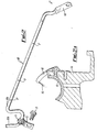
- Fig. 1 is a perspective view of an engine modified in accordance with the present invention;
- Figs. 2 and 2a are fragmentary views, respectively a nerspective view of a spray conduit and a Dart-sectional view showing the conduit connected to a cylinder head in a conventional internal combustion engine;
- Fig. 3 is a view similiar to that of Fig. 2 but showing the conduit modified and connected to a filter illustrated in exploded form; and
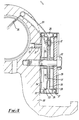
- Fig. 4 is a view similar to that of Fig. 2(a) but showing the filter in position connecting the conduit to the cylinder.block of an engine.
- The chosen example of engine of the invention is the British Ford Petrol engine 1600 OHC. or 2000 OHC currently in production.
- In this style of engine, camshaft lubrication oil ascends from the engine oil pumn and filter, both situated low down near the sump, through an oilway in the cylinder block, through a perforation in the cylinder head gasket, through an oilway in the cylinder head into the camshaft centre bearing pedestal from which it passes through a horizontally drilled oilway into the spray pipe assembly (Fig. 2).
- Fig. 2 is a pictorial view of an assembly consisting of a
spray pipe 10, nipple 11 andbracket 12. The assembly is that Ford Part which in U.K. is given No. 1490126 and which in Europe and U.S.A. is marked 70 HM 6578AF and DIFZ-6578A respectively. The assembly is secured by abolt 13 to the side of the camshaft centre bearing pedestal 14 (Fig. 2a) while the nipple 11 enters a horizontally drilledoilway 15, to receive and transmit oil to thepipe 10. From this noint oil flows into the fore and aft halves of the nine10a 10b finally to emerge as aspray 16 from each of eightspray holes 17, one spray lubricating each of eight cams (not illustrated). - The ends DR of the pipe are sealed, and secured by one bolt each (not shown) to the camshaft fore and aft bearing pedestals (also not shown).
- It is this existing system which is vulnerable to blocking of the
spray holes 17. - Another hazardous feature of this particular engine lies in the fact that the oil passes from an oilway in the cylinder block to an oilway in the cylinder head via the cylinder head gasket. Therefore, very special care must be taken, when changing the cylinder head gasket for maintenance purposes, that foreign matter, such as scrapings does not enter the oilway in either the cylinder block or the cylinder head, for on re-starting the engine, such matter could be carried along by the oil and block one or more of the spray holes.
- Referring simultaneously to Figs. 3 and 4, in an engine in accordance with the invention the innermost ends of
pine halves filter case 21 in such a manner that the said ends do not protrude into the inside of thecase 21 but the bores of thepipes case 21 is being made, holes for the ends of pipes 2Qa, 20b are punched out to form a shorttubular spigot 32 which facilitates brazing of the pipe ends to thecase 21 and increases the tolerance in the length to which thepipe halves - Filter components are assembled in the case (1) in the following order:

- This assembly is then secured to the camshaft centre bearing pedestal by a
bolt 30 which may be tightened solidly and yet apply a dimensionally controlled compression to the two '0' ring seals - At the same time a
nipple 31 on thecase 21 enters the horizontally drilled hole 15 (Fig. 4) in the camshaftcentre bearing pedestal 33 to admit oil to thefilter case 21. - The ends of the
pipes - Now referring to Fig. 3. On starting the engine, oil passes from the drilled
hole 15 in the camshaftcentre bearing pedestal 33 through thenipple 31 intochamber 34 from where any subsequent flow must be throughfilter screens 23 the whole area of which is available to pass oil but to stop particles greater than a given size and to collect such particles inchamber 34. - The now filtered oil flows through holes '35 in
plate 24 intoannulus 36 into the bores ofpipe 20 and is finally emitted from the spray holes onto the intended area of the cam.
Claims (10)
characterised in that
filter means is provided in the oil flow to the apertures to discourage solid particles from reaching and blocking the apertures.
characterised in that
the filter means communicates immediately with oil supply pines in which the spray apertures are provided.
characterised in that
two Dines connect with the filter means on a downstream side of a screen thereof and a chamber on an upstream side of the screen has a nipple communicating therewith and dimensioned to engage an oil supply cavity in structure of the engine.
characterised in that
the filter means comprises a case and, within the case, components for defining a chamber one on each side of the screen and sealing with the screen to enforce flow through the screen.
characterised in that
said components are secured in the case and the case is secured to the engine by a single fastener passing through the centre of all the components which are shaped to define a stack around the bolt.
characterised in that
the filter has a case which is central and supplies filtered oil to two pipes each of which has spray apertures therein.
characterised in that
components of the filter can be secured in the case and the case can be secured to an engine by a single central bolt.
Priority Applications (1)
| Application Number | Priority Date | Filing Date | Title |
|---|---|---|---|
| AT81305842T ATE13579T1 (en) | 1980-12-29 | 1981-12-10 | VALVE DRIVE LUBRICATION FOR AN ENGINE. |
Applications Claiming Priority (2)
| Application Number | Priority Date | Filing Date | Title |
|---|---|---|---|
| GB8041356 | 1980-12-29 | ||
| GB8041356 | 1980-12-29 |
Publications (2)
| Publication Number | Publication Date |
|---|---|
| EP0055901A1 true EP0055901A1 (en) | 1982-07-14 |
| EP0055901B1 EP0055901B1 (en) | 1985-05-29 |
Family
ID=10518225
Family Applications (1)
| Application Number | Title | Priority Date | Filing Date |
|---|---|---|---|
| EP81305842A Expired EP0055901B1 (en) | 1980-12-29 | 1981-12-10 | Valve gear lubrication for an internal combustion engine |
Country Status (3)
| Country | Link |
|---|---|
| EP (1) | EP0055901B1 (en) |
| AT (1) | ATE13579T1 (en) |
| DE (1) | DE3170777D1 (en) |
Cited By (1)
| Publication number | Priority date | Publication date | Assignee | Title |
|---|---|---|---|---|
| EP0694679A1 (en) * | 1994-07-29 | 1996-01-31 | Modine Manufacturing Company | Filter devices |
Citations (6)
| Publication number | Priority date | Publication date | Assignee | Title |
|---|---|---|---|---|
| US1938506A (en) * | 1932-07-05 | 1933-12-05 | Wellman Davis Milton | Valve guide lubricator |
| US2030646A (en) * | 1934-09-26 | 1936-02-11 | Longo Joseph | Lubricating device |
| FR1027936A (en) * | 1949-11-21 | 1953-05-18 | Lubricating device for upper valves of internal combustion engines | |
| GB820878A (en) * | 1956-11-05 | 1959-09-30 | Continental Motors Corp | Lubrication system for internal combustion engines |
| DE2620480A1 (en) * | 1976-05-08 | 1977-11-24 | Motoren Turbinen Union | Dry sump IC engine lubricant supply system - has cooled oil feed from main cycle to separate cycle for auxiliaries |
| EP0009564A1 (en) * | 1978-10-04 | 1980-04-16 | Klöckner-Humboldt-Deutz Aktiengesellschaft | Lubricating circuit for an internal-combustion engine |
-
1981
- 1981-12-10 EP EP81305842A patent/EP0055901B1/en not_active Expired
- 1981-12-10 DE DE8181305842T patent/DE3170777D1/en not_active Expired
- 1981-12-10 AT AT81305842T patent/ATE13579T1/en active
Patent Citations (6)
| Publication number | Priority date | Publication date | Assignee | Title |
|---|---|---|---|---|
| US1938506A (en) * | 1932-07-05 | 1933-12-05 | Wellman Davis Milton | Valve guide lubricator |
| US2030646A (en) * | 1934-09-26 | 1936-02-11 | Longo Joseph | Lubricating device |
| FR1027936A (en) * | 1949-11-21 | 1953-05-18 | Lubricating device for upper valves of internal combustion engines | |
| GB820878A (en) * | 1956-11-05 | 1959-09-30 | Continental Motors Corp | Lubrication system for internal combustion engines |
| DE2620480A1 (en) * | 1976-05-08 | 1977-11-24 | Motoren Turbinen Union | Dry sump IC engine lubricant supply system - has cooled oil feed from main cycle to separate cycle for auxiliaries |
| EP0009564A1 (en) * | 1978-10-04 | 1980-04-16 | Klöckner-Humboldt-Deutz Aktiengesellschaft | Lubricating circuit for an internal-combustion engine |
Cited By (1)
| Publication number | Priority date | Publication date | Assignee | Title |
|---|---|---|---|---|
| EP0694679A1 (en) * | 1994-07-29 | 1996-01-31 | Modine Manufacturing Company | Filter devices |
Also Published As
| Publication number | Publication date |
|---|---|
| DE3170777D1 (en) | 1985-07-04 |
| ATE13579T1 (en) | 1985-06-15 |
| EP0055901B1 (en) | 1985-05-29 |
Similar Documents
| Publication | Publication Date | Title |
|---|---|---|
| EP1065350B1 (en) | Combustion engine with a breather device | |
| US3485324A (en) | Piston cooling system | |
| US5695637A (en) | Combination full flow and bypass filter with venturi nozzle | |
| DE19544533C2 (en) | Lubrication system for a four-stroke engine | |
| EP1194680A1 (en) | Reciprocating internal combustion engine, comprising a camshaft | |
| DE102017108689A1 (en) | Reverse crankcase ventilation system during engine charging operation | |
| DE102009030556B4 (en) | Turbocharger system for an internal combustion engine with a turbocharger mounting base with a reduced footprint | |
| JPH02161119A (en) | Valve system lubricating device for overhead valve type engine | |
| EP0302438B1 (en) | Intake conduit part of an internal-combustion engine | |
| DE19756260A1 (en) | Oil separator for engine | |
| DE10336740B4 (en) | Piston cooling oil system with oil planer | |
| DE10159104B4 (en) | Internal combustion engine | |
| DE3342516A1 (en) | Internal combustion engine | |
| EP0251159B1 (en) | Return line for leak gas from a crank case | |
| US4430971A (en) | Internal combustion engine | |
| EP0356641B1 (en) | Cooling system for the valve seats in the cylinder head of an internal-combustion engine | |
| EP0055901B1 (en) | Valve gear lubrication for an internal combustion engine | |
| JPH08246871A (en) | Lubricating system for internal combustion engine | |
| DE10105555B4 (en) | Ventilation device for oil-laden gases of an internal combustion engine | |
| DE102005020959A1 (en) | Automotive engine lubrication system pump delivers oil to demand points by-passing oil radiator | |
| EP0358861B1 (en) | Device for purifying a lubricant | |
| DE19608503A1 (en) | Crankcase venting for internal combustion engine | |
| KR100539602B1 (en) | Lubrication oil passage structure of internal combustion engine | |
| JP2729646B2 (en) | Vertical type engine lubrication system | |
| DE19707597A1 (en) | Cyclone with ventilating valve behind it in flow direction |
Legal Events
| Date | Code | Title | Description |
|---|---|---|---|
| PUAI | Public reference made under article 153(3) epc to a published international application that has entered the european phase |
Free format text: ORIGINAL CODE: 0009012 |
|
| AK | Designated contracting states |
Designated state(s): AT BE CH DE FR GB IT LU NL SE |
|
| KL | Correction list |
Free format text: 82/05 |
|
| RBV | Designated contracting states (corrected) |
Designated state(s): AT BE CH DE FR GB IT LI LU NL SE |
|
| 17P | Request for examination filed |
Effective date: 19830104 |
|
| ITF | It: translation for a ep patent filed |
Owner name: BARZANO' E ZANARDO ROMA S.P.A. |
|
| GRAA | (expected) grant |
Free format text: ORIGINAL CODE: 0009210 |
|
| AK | Designated contracting states |
Designated state(s): AT BE CH DE FR GB IT LI LU NL SE |
|
| REF | Corresponds to: |
Ref document number: 13579 Country of ref document: AT Date of ref document: 19850615 Kind code of ref document: T |
|
| PG25 | Lapsed in a contracting state [announced via postgrant information from national office to epo] |
Ref country code: SE Effective date: 19850530 |
|
| REF | Corresponds to: |
Ref document number: 3170777 Country of ref document: DE Date of ref document: 19850704 |
|
| REG | Reference to a national code |
Ref country code: CH Ref legal event code: PL |
|
| ET | Fr: translation filed | ||
| PG25 | Lapsed in a contracting state [announced via postgrant information from national office to epo] |
Ref country code: GB Effective date: 19851210 Ref country code: AT Effective date: 19851210 |
|
| PG25 | Lapsed in a contracting state [announced via postgrant information from national office to epo] |
Ref country code: LU Free format text: LAPSE BECAUSE OF NON-PAYMENT OF DUE FEES Effective date: 19851231 |
|
| PLBI | Opposition filed |
Free format text: ORIGINAL CODE: 0009260 |
|
| 26 | Opposition filed |
Opponent name: MTU MOTOREN- UND TURBINEN-UNION FRIEDRICHSHAFEN GM Effective date: 19860218 |
|
| NLR1 | Nl: opposition has been filed with the epo |
Opponent name: MTU MOTOREN- UND TURBINEN-UNION FRIEDRICHSHAFEN GM |
|
| BERE | Be: lapsed |
Owner name: HOLDING NORMAN Effective date: 19851231 |
|
| PG25 | Lapsed in a contracting state [announced via postgrant information from national office to epo] |
Ref country code: NL Effective date: 19860701 |
|
| GBPC | Gb: european patent ceased through non-payment of renewal fee | ||
| NLV4 | Nl: lapsed or anulled due to non-payment of the annual fee | ||
| PG25 | Lapsed in a contracting state [announced via postgrant information from national office to epo] |
Ref country code: FR Free format text: LAPSE BECAUSE OF NON-PAYMENT OF DUE FEES Effective date: 19860829 |
|
| REG | Reference to a national code |
Ref country code: FR Ref legal event code: ST |
|
| RDAG | Patent revoked |
Free format text: ORIGINAL CODE: 0009271 |
|
| STAA | Information on the status of an ep patent application or granted ep patent |
Free format text: STATUS: PATENT REVOKED |
|
| GBPR | Gb: patent revoked under art. 102 of the ep convention designating the uk as contracting state | ||
| 27W | Patent revoked |
Effective date: 19880529 |
|
| REG | Reference to a national code |
Ref country code: CH Ref legal event code: PL |