EP0055501A1 - Device for transporting and/or spreading liquids - Google Patents
Device for transporting and/or spreading liquids Download PDFInfo
- Publication number
- EP0055501A1 EP0055501A1 EP81201387A EP81201387A EP0055501A1 EP 0055501 A1 EP0055501 A1 EP 0055501A1 EP 81201387 A EP81201387 A EP 81201387A EP 81201387 A EP81201387 A EP 81201387A EP 0055501 A1 EP0055501 A1 EP 0055501A1
- Authority
- EP
- European Patent Office
- Prior art keywords
- valve
- coupling device
- inlet
- conduit
- hydraulic
- Prior art date
- Legal status (The legal status is an assumption and is not a legal conclusion. Google has not performed a legal analysis and makes no representation as to the accuracy of the status listed.)
- Ceased
Links
- 230000007480 spreading Effects 0.000 title claims description 33
- 239000007788 liquid Substances 0.000 title abstract description 5
- 230000008878 coupling Effects 0.000 claims abstract description 96
- 238000010168 coupling process Methods 0.000 claims abstract description 96
- 238000005859 coupling reaction Methods 0.000 claims abstract description 96
- 230000007246 mechanism Effects 0.000 claims description 63
- 239000012530 fluid Substances 0.000 claims description 55
- 238000004891 communication Methods 0.000 claims description 7
- 238000006073 displacement reaction Methods 0.000 claims description 2
- 210000003608 fece Anatomy 0.000 abstract description 16
- 239000010871 livestock manure Substances 0.000 abstract description 16
- 230000000694 effects Effects 0.000 abstract description 3
- 239000000463 material Substances 0.000 description 21
- 238000010276 construction Methods 0.000 description 12
- 230000033001 locomotion Effects 0.000 description 11
- 230000001105 regulatory effect Effects 0.000 description 11
- 230000009471 action Effects 0.000 description 6
- 230000008901 benefit Effects 0.000 description 4
- 230000006835 compression Effects 0.000 description 3
- 238000007906 compression Methods 0.000 description 3
- 230000001276 controlling effect Effects 0.000 description 3
- 238000010586 diagram Methods 0.000 description 2
- 239000011344 liquid material Substances 0.000 description 2
- 238000000034 method Methods 0.000 description 2
- 230000008569 process Effects 0.000 description 2
- 238000005086 pumping Methods 0.000 description 2
- 230000000717 retained effect Effects 0.000 description 2
- 238000013459 approach Methods 0.000 description 1
- 230000005540 biological transmission Effects 0.000 description 1
- 230000000903 blocking effect Effects 0.000 description 1
- 230000003247 decreasing effect Effects 0.000 description 1
- 238000007599 discharging Methods 0.000 description 1
- 230000000630 rising effect Effects 0.000 description 1
- 238000010079 rubber tapping Methods 0.000 description 1
- 239000007921 spray Substances 0.000 description 1
Images


Classifications
-
- A—HUMAN NECESSITIES
- A01—AGRICULTURE; FORESTRY; ANIMAL HUSBANDRY; HUNTING; TRAPPING; FISHING
- A01C—PLANTING; SOWING; FERTILISING
- A01C23/00—Distributing devices specially adapted for liquid manure or other fertilising liquid, including ammonia, e.g. transport tanks or sprinkling wagons
- A01C23/04—Distributing under pressure; Distributing mud; Adaptation of watering systems for fertilising-liquids
- A01C23/045—Filling devices for liquid manure or slurry tanks
Landscapes
- Life Sciences & Earth Sciences (AREA)
- Engineering & Computer Science (AREA)
- Water Supply & Treatment (AREA)
- Soil Sciences (AREA)
- Environmental Sciences (AREA)
- Fertilizing (AREA)
- Catching Or Destruction (AREA)
Abstract
A manure spreader comprises a tank (1) for receiving liquid manure from a pit (61). The manure enters the tank (1) through a conduit (60) temporarily connected to an inlet (2) by a coupling device (46). To spread the manure, a distribution member (16) is fitted to the inlet (2) (which then serves as an outlet). A valve (3) is provided for shutting off the inlet (2) from the tank (1). A control linkage (21) is provided for operating the coupling device (46), the distribution member (16) and the valve (3). The control linkage (21) in constructed so that the valve (3) only opens when the inlet (2) is connected to the conduit (60) or the distribution member (16) to avoid the unpleasant effects of accidental manure spillage.
Description
- The invention relates to a device for transporting and/or spreading fluids comprising a hopper having an inlet and an outlet and a closing member located between the inlet or outlet respectively and the hopper, said device having a coupling device by means of which a feeding conduit can be connected with the inlet, and/or having a discharge means to be coupled with the outlet.
- One object of the invention is to provide a robust and simply controllable device of the kind set forth. According to the invention this can be achieved by providing the device with operating means which, subsequent to energization, actuates either the coupling device or the discharge means, so that the feeding conduit is automatically pressed against the inlet or, respectively the discharge means is automatically pressed against the outlet of the hopper or which actuates in order of succession either the coupling device or the discharge means so that the feeding conduit is automatically pressed against the inlet or, respectively, the discharge means is automatically pressed against the outlet of the hopper and which subsequently actuates the closing member so that it is opened, whilst after the use of the device the operating means can again actuate the coupling device or the discharge means so that either the coupling device automatically disengages the feeding conduit and/or the discharge means is automatically removed from the outlet or the closing member is automatically closed and subsequently either the coupling device disengages the feeding conduit and/or the discharge means is automatically removed from the outlet. In this way the connection of the feeding conduit or the discharge means can be readily established so that a job can be economically carried out by means of this device.
- Particularly when the equipment comprises two grabs movable along the inlet/outlet pipe, simple connection of the feeding conduit with the inlet pipe can be very satisfactorily carried out.
- A further advantage is that the entire mechanism employed for coupling can be arranged on existing equipment for transporting and spreading fluids, also termed mixed manure distributors.
- The invention relates not only to the equipment itself but also to the operating means itself and to those elements which are useful for a satisfactory operation of the equipment such as a support of the feeding conduit, an indicating device for the operating means and the use of wheel guides near the feeding conduit.
- For a better understanding of the present invention and to show how it may be carried into effect, reference will now be made, by way of example, to the accompanying drawings, in which:
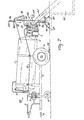
- Figure 1 is a side view of a manure spreader;
- Figure 2 is an enlarged end view of part of the spreader of Figure 1 in the direction of the arrow II in Figure 1;
- Figure 3 is, on a scale corresponding with Figure 2, a fragmentary view taken in the direction of the arrow III in Figure 1;
- Figure 4 is an enlarged sectional view taken on the lines IV - IV in Figure 1;"
- Figure 5 is an enlarged fragmentary side view of the spreader in one operative condition;
- Figure 6 corresponds to Figure 5 but represents another operative condition;
- Figure 7 shows another construction for a manure spreader;
- Figure 8 is an enlarged fragmentary view taken in the direction of the arrow VIII in Figure 7;
- Figure 9 is an enlarged fragmentary side view of the spreader of Figure 7 in one operative condition;
- Figure 10 corresponds to Figure 9 but represents another. operative condition;
- Figure 11 is an enlarged fragmentary view taken in the direction of the arrow XI in Figure 7;
- Figure 12 is a view taken in the direction of the arrow XII in Figure 11;
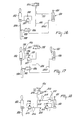
- Figure 13 is a partly schematic side view of an alternative construction for part of the spreader shown in Figure 7;
- Figure 14 shows another construction for the part shown in Figure 13;
- Figure 15 shows on an enlarged scale a component of the construction of Figure 14; and
- Figures 16 to 18 show schematically three variants for the spreader of Figure 7.
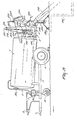
- Figure 19 is a side elevation of a device embodying the invention.
- Figure 20 shows on an enlarged scale part of the side elevation of the device shown in Figure 19.
- Figure 21 shows on an enlarged scale part of the device taken in the direction of the arrow XXi in Fig. 19.
- Figure 22 is partly an elevational view and partly a sectional view of part of the device of Figure 20 on an enlarged scale.
- Figure 23 is a sectional view of the part of Figure 22 taken on the line XXIII - XXIII in Figure 22.
- Figure 24 shows the hydraulic diagram of the relative coupling of the hydraulic parts of the device.
- Figure 25 shows a position of the indicating members for a given position of the various parts of the device.
- Figure 26 shows a position of the indicating members for a different position of the various parts of the device.
- Figure 27 shows a further position of the indicating members.
- Figure 28 shows a position of the indicating members for a further position of the various parts of the device.
- Figure 29 shows a position of the indicating members for a further different position of the various parts of the device.
- Figure 30 is an elevational view corresponding with that of Figure 20 of the device embodying the invention, in which a feeding conduit with manually operable coupling is arranged.
- The equipment illustrated in the Figures is intended for use as a mixed manure spreader, but it can be used for other purposes. It comprises a container in the form of a
tank 1 having aninlet 2, which may also serve in the spreader shown in Figure 1 as an outlet. Theinlet 2 is provided with a closing member in the form of avalve 3. Thetank 1 is supported on a frame 5 which has ground wheels 4 and, at the front, adraw eyelet 6 to enable the spreader to be hitched to a tractor or a similar vehicle so as to be towed. - A
pump 7 is mounted on the frame 5 and is connected by apipe 8 with the top of thetank 1. A valve mechanism (now shown) in the connection between thepump 7 and thepipe 8 is provided withanadjusting arm 9 for selectively connecting either the suction or pressure side of thepump 7 to the tank so that thepump 7 can apply suction or pressure to the tank. - The frame 5 is provided with a
jockey wheel 10, on which the spreader can be supported when it is not coupled by thedraw eyelet 6 with a tractor. - The inlet or
outlet 2 comprises acomponent 11 and acomponent 12 disposed one on each side of thevalve 3, thecomponent 11 being connected to the tank. Thecomponent 12 is provided on both sides withside plates support 15. The spreader comprises discharge means in the form of adistribution member 16 having a spreadingplate 16A. Thedistribution member 16 is mounted on abracket 17 which is supported by twoarms 18 on thesupport 15 for pivotal movement about apivotal shaft 20. For thispurpose sleeves 19 are secured to thearms 18, these sleeves being pivotable about thepivotal shaft 20 which is supported by theside plates arms 18 and thebracket 17 are at an angle 17A of about 125° to one another. - The
distribution member 16 and thevalve 3 are intercoupled by acontrol linkage 21 which is adjustable by ahydraulic control mechanism 22. Thecontrol mechanism 22 comprises ahydraulic cylinder 22A in which apiston rod 23 is movable. Thepiston rod 23 is pivotally coupled by ashaft 24 with alever arm 25 of thelinkage 21 which is rigidly secured to one of the sleeves 19 (Fig. 2). Thecylinder 22A is pivotally coupled by ashaft 26 with arocker 27 of thelinkage 21. The illustrated embodiment shows the preferred construction, in whichcylinder 22A is a double-acting cylinder. Alternatively, two single- acting cylinders operating in opposite senses could be used. Therocker 27 is pivotable about a rockingshaft 28, which is secured to alug 29 fastened to theinlet 2. The end of therocker 27 away from theshaft 26 is pivotally coupled by apin 30 to a connectingarm 31 with offset ends, this connectingarm 31 being part of thelinkage 21. At one of the bends in the connectingarm 31 there is a stiffening plate 32 (Figure 2). The connectingarm 31 is pivotally coupled by a pin 33 with alever 34 of thelinkage 21. Thelever 34 is pivotally coupled by apin 35 with acontrol rod 36 of theclosing member 3. Thelever 34 is furthermore pivotally coupled by apin 37 with apivotal arm 38 of thelinkage 21. To thispivotal arm 38 is rigidly secured a sleeve 43, which is rotatable on thepivotal shaft 20 between the supportingplates pivotal arm 38 is thus pivotable about the horizontalpivotal shaft 20 located above theinlet 2 respectively. Atension spring 39 is arranged between thelever 34 and atag 40 secured to thecomponent 12. - The
hydraulic control mechanism 22 can be releasably coupled byducts - The spreader is provided with a
coupling device 46 having twoidentical parts 46A and 46B, which are each rigidly secured to tags 47 which, in turn, are rigidly fastened to the outer ends of thesleeves 19 surrounding thepivotal shaft 20. Thus thecoupling device 46 is firmly connected by thesleeves 19 to thedistribution member 16. Thedistribution member 16 and thecoupling device 46 are disposed at an angle to one another, as is shown in the side views of Figures 1, 5 and 6. Eachpart grab 45. In this embodiment the centre line X-X of the distribution member is at an angle of about 45° to the axis Y-Y of thegrabs 45. As is shown in Figure 2, the twograbs 45 of thecoupling device 46 can be positioned one on each side of theinlet 2. Thegrabs 45 each comprise abracket 48 providing a V-shaped guide part 49 (Figures 5 and 6). In the position shown-in Figure 5 the apex of the V-shapedguide part 49 is located at the level of the centre line of theinlet 2, the V opening in the direction of normal travel of the mixed manure spreader. Near the opening of theinlet 2 is arranged aconical guide member 51 which has alower part 52 comprising a part- conical lower plate and has twoupper parts 53 in the form of cone sectors. Thelower part 52 is separated by V-shapedrecesses 54 from each of theupper parts 53. As will be apparent, for example,-from Figure 2, the V-shapedrecesses 54 are symmetrically located one on each side of a vertical plane going through the centre line of theinlet 2. Theplates 53 are separated from one another by aslot 55 located, as can be seen, for example, in Figure 2, centrally above the opening of theinlet 2 and shaped in a manner such that thearm 17 can move therein when the distribution member 16 (Figure 6) is fitted to theinlet 2. Therecesses guide member 51 to near the opening of theinlet 2. - As is shown in Figure 1, the spreader co-operates with a
conduit 60, which projects into apit 61 and constitutes a filling conduit. Theconduit 60 is mounted on aframe 62. Theframe 62 comprises an annular carrier 63 (Figure 4), which is concentric with theconduit 60.Springs 64 support theconduit 60 in a slightly movable fashion relative to thecarrier 63. Thecarrier 63 is arranged on aframework 67 bybrackets 65 supported bystruts 66. Theframework 67 hasfeet 68, which are vertically adjustable in guidingsleeves 69. The feet can be set in any one of a plurality of positions by means of lockingpins 70 so that the framework can be set at various heights above the ground. As is visible in Figure 3, theconduit 60 has capturing arms 71 rear its end. The capturing arms 71 are arranged on opposite sides of theconduit 60 and extend at least substantially horizontally away from theconduit 60. - Each capturing arm 71 is V-shaped, the V opening to the rear with respect to the direction of normal travel of the mixed manure spreader. Their dimensions and shape are such that they can co-operate with the
grabs 45. - The spreader can be operated to introduce a fluid or liquid material such as mixed manure into the tank by suction, and to discharge the material from the tank under pressure. The material can be sucked into the tank through the
conduit 60, for example, from the collectingpit 61. The material can be discharged and, for example, be spread out by means of thedistribution member 16. - In more detail, the spreader can be operated as follows:
- The
draw eyelet 6 of the spreader can be coupled with a tractor or a similar vehicle. Thepump 7 can be linked by drivingshaft 72 to the power take-off shaft of the tractor. The spreader can be manoeuvred so that, for example, by driving backwards, theguide member 51 is positioned in front of the opening of the conduit 60 (Figure 3). In order to position theguide member 51 and hence the opening of theinlet 2 most effectively in front of the end of thestationary conduit 60 near thepit 61, awheel guide 73 may be stationed on the ground near theframe 62 so that by driving the spreader backwards the wheels 4 can cooperate with theguide 73. While the spreader is being manoeuvred towards theconduit 60, thepump 7 is switched off and thevalve 3 is closed. In order to permit connection of the conduit 60-with theinlet 2, thedistribution member 16 and thecoupling device 46 are moved into the position shown in Figure 1. This leaves unobstructed theinlet 2. Thecoupling device 46 is in a position in which thegrabs 45 are located to the rear of and above theinlet 2, whilst the V-shapedguide part 49 opens downwardly. In this position of the distribution member and thecoupling device 46 and with thevalve 3 closed, thehydraulic ram 22A is actuated through theoil pressure ducts piston rod 23 is retracted substantially completely inside thecylinder 22 as is shown in Figure 1, the distance between thepivotal shafts inlet 2 and theguide member 51 are completely unobstructed. The spreader can then be manoeuvred so that the end of theconduit 60 enters theguide member 51. Thewheel guide 73 may comprise a stop 75 as is shown in Figure 1. The wheel 4 strikes this stop when the opening 74 is near theopening 76 of theconduit 60. If desired, the stop 75 may be adjustable for adapting its position to the dimensions of different mobile devices. - When the
openings 74 and 76 are substantially adjoined and theconduit 60 is moved into its correct place by theguide member 51, thecoupling device 46 can be turned about thepivotal shaft 20 in the clockwise direction, as viewed in Figures 1, 5 and 6 by means of thelinkage 21 by actuating thehydraulic control mechanism 22. For this purpose the pressure in thecylinder 22A is raised so that thepiston rod 23 is extended from thecylinder 22A and the distance between thepivotal shafts spring 39, acting through thelever 34, thearm 31 and therocker 27, maintains the position of therod 26. Thus thevalve 3 remains closed. The increase in distance between theshafts lever arm 25 to pivot about the pivotal shaft- 20, so turning thesleeves 19 fastened to thelever arm 25 about theshaft 20. The parts of the coupling device rigidly secured to thesleeves 19 will thus also turn about theshaft 20 in a clockwise direction (see arrow 78) out of the position shown in Figure 1. This brings the V-shapedguide parts 49 of thegrabs 45 into contact with the V-shaped capturing arms 71 of theconduit 60 as is shown in Figure 3. By the action of thecontrol mechanism 22, thecoupling device 46 tends to move in the direction of thearrow 78 over a distance such that theopening 76 is brought into contact with the opening 74. In this position the coupling between theconduit 60 and theinlet 2 is established. - To fill the tank from the pit, the
valve 3 has to be opened. This can be done by continuing the operation of thecontrol mechanism 22 so that with higher pressure in thecylinder 22A therod 23 is moved further out of thecylinder 22A so that the distance between theshafts pivotal shaft 24 cannot move further upwards, because thecoupling device 46 is prevented from turning in thedirection 78 by the abutment of theopening 76 against the opening 74. Consequently thepin 26 will be pushed downwardly. As a result therocker 27 will turn about the rockingshaft 28. This motion will be transmitted by thetie arm 31 to move thelever 34 upwardly against the force of thespring 39. This upwards movement of thelever 34 raises therod 36 of the valve to open thevalve 3. The fully open position is reached when thelever 34 arrives at the position shown in broken lines in Figure 5. During its upwards movement thelever 34 pivots about thepivotal shaft 37, but thepivotal shaft 35 can nevertheless move perpendicularly upwards in the lengthwise direction of therod 36 since theshaft 37 can move slightly as a result of rotation of thearm 38 about the pivotal-shaft 20. When thevalve 3 is opened and theconduit 60 is firmly.coupled with theinlet 2, thepump 7 can draw air out of thetank 1 so that thetank 1 is filled through theconduit 60. The air can be sucked out of thetank 1 by thepump 7 by setting thearm 9 so that theconduit 8 is connected with the suction side of thepump 7. - When the
tank 1 is filled to a desired level, the spreader can be disconnected from theconduit 60. To do this, thecontrol mechanism 22 is actuated so that thepiston rod 23 is retracted into thecylinder 22A so as to reduce the distance between theshafts pump 7 is switched off so that air is no longer withdrawn from thetank 1, and then, under the action of thespring 39, first thevalve 3 is closed, and then thegrabs 45 are swung to the rear to release theconduit 60. - The spreader can then be moved to the place where the material withdrawn from the collecting
pit 61 has to be distributed. In the illustrated embodiment, the material can be discharged from thetank 1 through theinlet 2, which then becomes an outlet. To distribute the material, thedistribution member 16 is fitted to theoutlet 2. After releasing theconduit 60, thedistribution member 16 and thegrabs 45 are in the ' position shown in Figure 1. Oil can be fed to thecontrol mechanism 22 to extend therod 23 from thecylinder 22A so that, as described above, thesleeve 19 with thearm 25 turns in thedirection 78 about thepivotal shaft 22. This swings thedistribution member 16 in thedirection 78 about thepivotal shaft 20. This time, thegrabs 45 will not meet the capturing arms 71 of theconduit 60, and so the assembly of thedistribution member 16 and thecoupling device 46 will move further than before, until thearms 46A and 46B with thegrabs 45 move, one on each side, along theinlet 2 into the position shown in Figure 6. Thus thedistribution member 16 having anopening 77 will.abut the opening 74. When thedistribution member 16 engages theinlet 2, it cannot turn further in the direction of thearrow 78 and consequently thepoint 24 is prevented from moving further upwards. - As described above, the
shaft 26 will then move downwards by the action of thecontrol mechanism 22. As a result thelever 34 will be raised into the position shown in Figure 6 so that thevalve 3 is opened. Immediately before, or at the same time as,valve 3 is opened, thepump 7 can be switched on and to pump air into the tank so that the material in the tank is pressurised. Continued operation of the pump causes the material in the tank to be discharged under pressure through theoutlet 2 to be spread by thedistribution member 16. Thus the material can be spread uniformly over a broad strip during travel of the spreader. - When the tank is empty, the
pump 7 can be switched off and thevalve 3 can be closed by thecontrol mechanism 22, after which thedistribution member 16 and thecoupling device 46 can be swung back into the position shown in Figure 1. Thecontrol mechanism 22 can be advantageously actuated from the tractor via the ducts 41-and 42, which can be coupled with the hydraulic system of the tractor. The spreader can then be returned to the collectingpit 61 for recharging. - Figures 7 to 12 show another spreader. Those parts ofthis spreader which correspond with parts of the spreader shown in Figures 1 to 6 are designated by the same reference numerals.
- In the spreader shown in Figures 7 to 12 the
control mechanism 22 is coupled with an indicatingdevice 80 and thepit conduit 60 is arranged in a different manner in a supportingframe 56. Theframe 56 comprises twoground beams 57 extending transversely of the length of theconduit 60, as is shown in Figure 11. The ends of the ground beams 57 are interconnected by bridgingmembers 58. Themembers 58 are provided withsockets 59, in which upwardly extendingpillars 79 are slidable. Awasher 94 fits over eachpillar 79 and between saidwashers 94 and thesockets 59 there arecompression springs 95 which surround thepillars 79. Above eachwasher 94 there is a retainingclip 103 which can be fitted at will into any one of a plurality ofholes 104 in thepillars 79. The top ends of thepillars 79 are provided with capturingarms 105, which are connected with thepit conduit 60 near itsopening 76. The capturingarms 105 are arranged one on each side of theconduit 60 and extend away from theconduit 60 at least substantially horizontally. The capturingarms 105 are V-shaped (Figure 11), the open side of the V facing in the opposite direction to theopening 76. The capturingarms 105 are shaped and proportioned so that they can cooperate with thegrabs 45 of the twoparts 46A and 46B of thecoupling device 46. - The
control mechanism 22 of thelinkage 21 and hence thedistribution member 16 and thelocking device 46 as well as thevalve 3 are coupled with the indicatingdevice 80. The indicatingdevice 80 is shown at the front of thetank 1, but it could be elsewhere on the spreader. - The indicating
device 80 is coupled with themechanism 22 by aflexible connection 81 comprising anouter sheath 82 and aninner cable 83. Theconnection 81 may have any length as required. It is, for example, possible to mount the indicatingdevice 80 in the cab of the tractor or other prime mover to which the spreader is hitched. Thesheath 82 is supported at one end by atag 84 rigidly secured to thepiston rod 23. The inner cable is fastened at one end to theshaft 26, but it could be fastened to the cylinder 22A.at a different place. Thesheath 82 is supported at the other end by a bearinghousing 85, which is arranged centrally on adial plate 86 of the indicatingdevice 80. In the bearing housing theinner cable 83 is connected with theshaft 87, to which a pointer 88 is secured. Thedial plate 86 has indication points 89 to 93. The bearinghousing 85 comprises a mechanism biassing the pointer 88 towards thepoint 89. Traction applied to theinner cable 83 can overcome the biassing mechanism to move the pointer 88 at least to thepoint 93. - The
frame 56 is provided with a direction indicator in the form of a rod or pipe comprising an at least substantially horizontal:part 96 connected, possibly integrally, to an upwardly extendingsupport 97. Thesupport 97 is mounted in asleeve 98 which is rigidly secured to thesupport 59. Thesupport 97 is vertically slidable in thesleeve 98 and can be fixed at will in any one of a plurality of positions by a fixing member shown as abolt 99. Thedirection indicator 96 is intended to be used with adirection pin 100, which is rigidly secured to thetank 1. Thepin 100 is located beyond the rear of the tank in a position such that when theinlet 2 is in contact with theconduit 60 thepin 100 is located near thehorizontal part 96. - The spreader can be used in the same way as that of Figures 1 to 6 for charging the tank with a fluid or liquid material such as mixed manure by suction, for transporting the material and for discharging it from the tank under pressure.
- As before, the spreader will be manoeuvred so that, for example, by driving backwards, the
guide member 51 is positioned in front of the opening of theconduit 60. In this embodiment theguide member 51 and hence the opening of theinlet 2 can be moved accurately to the required position in front of thestationary conduit 60 disposed near thepit 61 with the aid of thedirection pin 100 and the direction indicator arranged on theframe 56. Thedirection pin 100 and the direction indicator are disposed so that they are constantly visible, during manoeuvring, from the driver's seat of the tractor to which the spreader is hitched. Thepin 100 and the indicator are arranged so that when thepin 100 is moved near to thehorizontal part 96 of the indicator theguide member 51 is correctly in front of theopening 76 of theconduit 60. The tractor can be manoeuvred so that thepin 100 approaches the direction indicator. Thehorizontal part 96 has such alength 101 that when thepin 100 is located within thelength 101 near theindicator 96, theguide member 51 is located accurately in front of theopening 76 of theconduit 60. Thus theguide member 51 can be readily moved near to theconduit 60 without the need to be able to see these parts from the tractor. - Coupling of the
conduit 60 with theinlet 2 is assisted, as in the previous embodiment, by the slight resilience of theconduit 60 with respect to its supportingframe 56. In this embodiment, the resiliently guiding support is formed by thesockets 58 and thesprings 95. This will facilitate the establishment of the connection of the opening 74 of theinlet 2 with theopening 76. The height of theopening 76 above the ground can be adjusted to the height of theinlet 2 by inserting theclip 103 into adifferent hole 104. In order to prevent theinlet 2 from pushing thepit conduit 60 in the direction towards thepit 61, astop 102 for the wheels 4 may be provided as is indicated in Figure 7. This stop can be arranged at such a distance from theframe 56 that the wheels 4 come into contact with it when the opening 74 is located near theopening 76. Then, in addition, thedirection pin 100 will be located ne2r thehorizontal part 96 of thedirection indicator 96. - The distance of the
stop 102 from theframe 56 may, if desired, be adjustable for adapting the position of the stop to the dimensions of the spreader. Similarly, the height of thehorizontal part 96 of.the indicator can be adjusted. - The coupling of the
pit conduit 60 with theinlet 2 by means of thecoupling device 46 or the coupling of thedistribution member 16 with theinlet 2 as well as the position of thevalve rod 36 are not visible in practice from the driver's seat of the tractor. In order to provide an indication of the positions of these components, thecontrol mechanism 22 is coupled with the indicatingdevice 80 by theconnection 81. - From the foregoing description it will be appreciated that the various positionsof the
distribution member 16, thecoupling device 46 and therod 36 of thevalve 3 are determined by the length-by which therod 23 extends from thecylinder 22A, and consequently this length is used for indicating the positions of themembers inner cable 83 is connected with thecylinder 22A by means of its connection with the shaft :26. Theouter sheath 82 is supported by thetag 83 coupled with therod 23. The distance between thetag 84 and theshaft 26 determines the distance over which theinner cable 83 is drawn out of theouter sheath 82, and consequently also determines the position of the pointer 88 with respect to thedial plate 86 owing to the connection of thecable 83 to theshaft 87 on which the pointer 88 is mounted. The length by which theinner cable 83 is located outside theouter sheath 82 depends on the positions into which are moved thedistribution member 16, thecoupling device 46 and therod 36 by the part of therod 23 lying outside thecylinder 22A. When thedistribution member 16, thecoupling device 46 and therod 36 are in the position shown in Figure 7, thecable 83 extends by the minimum distance out of theouter sheath 82 and the distance between thetag 84 and theshaft 26 is at a minimum. In this position the pointer 88 is retained atpoint 89, as shown in Figure 6, by the biassing mechanism in the bearinghousing 85. If thecoupling device 46 is moved into the position shown in Figure 9 for connecting theinlet 2 with theconduit 60,.the distance between thetag 84 and theshaft 26 will increase. Theinner cable 83 will be drawn out of theouter sheath 82 over a distance such that theshaft 87 turns to bring the pointer 88 to point 90. This position of the pointer 88 thus indicates that the position shown in Figure 9 is attained. When at the position of Figure 9 the closingmember 3 is opened and therod 36 moves into the position shown in broken lines in Figure 9, the distance between thetag 84 and theshaft 26 is increased again and therocker 27 is turned into the position indicated by broken lines in Figure 9. As a result theinner cable 83 will cause theshaft 87 to turn to bring the pointer 88 to point 92. Consequently the position of the pointer 88near point 92 indicates that the coupling of theconduit 60 with theinlet 2 is established and that thevalve 3 is open. - In the position shown in Figure 10 the
distribution member 16 is coupled with theinlet 2, which then serves as the outlet. To achieve this, thepiston rod 23 is moved into the position shown in Figure 10, and therocker 27 occupies the position shown in broken lines in Figure 10. The distance between thetag 84 and theshaft 26 is then such that the pointer 88 is atpoint 91. From this position theshaft 26 is pushed downwards and therocker 27 turns into the position indicated by solid lines in Figure 10. In this position the distance between thetag 84 and theshaft 26 is such that thecable 83 has moved the pointer 88 to thepoint 93. At this position of the pointer 88 thevalve 3 is opened and thedistribution member 16 is in contact with the opening of theoutlet 2. From this position the device can again be moved into the initial position by moving thedistribution member 16 into the position shown in Figure 7, in which the pointer 88 returns to point 89. Inthe manner described above the indicatingdevice 80 formed by the pointer 88 and thedial 86 provides an indication of the various positions of theparts - Figure 13 shows a different embodiment for controlling the
valve 3 in conjunction with the actuation of thehydraulic control mechanism 22. In this embodiment thehydraulic control mechanism 22 is not connected through a mechanical linkage with thevalve 3; instead thevalve 3 is provided with a separate hydraulicvalve control mechanism 115. In Figure 13 thehydraulic system 110 of the tractor or a similar vehicle to which the spreader is hitched is shown schematically and comprises acontrol arm 111 and aregulating mechanism 112. Theregulating mechanism 112 andducts control mechanisms duct 113 is connected with thecylinder 22A near theshaft 26, which is pivotably mounted in this embodiment directly on thepart 12 of theinlet 2. The opposite end of thecylinder 22A communicates through aduct 114 with thereturn duct 118. Theduct 114 includes anon-return valve 122. Thehydraulic control mechanism 115 is fastened to asupport 116 secured to thetank 1. Thehydraulic control mechanism 115 comprises acylinder 109 within which a piston rod 108 is movable. The piston rod 108 is coupled with thevalve operating rod 36. The end of thecylinder 109 nearer therod 36 communicates through aduct 117 with theduct 113. Theduct 117 includes apressure relief valve 119. - Between the
ducts duct 120 having anon-return valve 121. The end of thecylinder 109 away from thevalve 3 communicates with the duct. 118 and between theducts duct 128 having.apressure relief valve 123. As in the preceding embodiment thecontrol mechanism 22 is linked by acable connection 82 with an indicatingdevice 80 having indicatingpoints distribution member 16 or thecoupling device 46. Since in the embodiment of Figure 13 thecontrol mechanism 22 is coupled with thevalve 3 in a different manner an indication of the position of thevalve 3 is not transmitted through thecable 82 from thecontrol mechanism 22. Instead, theouter sheath 124 of a further flexible connecting cable is connected to thecylinder 109, and.theinner cable 125 of the flexible cable is fixed to thevalve stem 36. Thesheath 124 is coupled with aslide 126, which is movable along awindow 127, which may be fastened, as shown in Figure 13,to thedial plate 86. - In this embodiment, operation is as follows.
- In order to connect the
hose 60 the vehicle is driven to near the supportingmeans hose 60 is near thepart 12, thecoupling member 46 is turned so that it urges thehose 60 against theinlet 2. To do this, hydraulic fluid is supplied to thecylinder 22A thorugh theregulating mechanism 112 from the tractor so that thepiston rod 23 moves thecoupling mechanism 46 into the position corresponding with the position of thecoupling mechanism 46 indicated in Figure 9. In this position, the piston rod cannot move further out of thecylinder 22A and consequently the pressure in theduct 113 increases. Thepressure relief valve 119 is set so that it opens under this increased pressure to allow hydraulic fluid to flow from theduct 113 into theduct 117 and through the latter to thecylinder 109. This drives the piston rod 108 and thevalve operating rod 36 upwardly to open thevalve 3. - As in the preceding embodiment, material can be sucked into the
tank 1 through theconduit 60, when thevalve 3 is open. The closed or opened position of thevalve 3 can be indicated by theslide 126 in front of thewindow 127. For example, when thevalve 3 is closed, theinner cable 125 positions theslide 126 so that a red section of it appears at thewindow 127. When the valve is open, theinner cable 125 is displaced, for example, under the action of a spring mechanism arranged in atransmission member 129, so displacing the slide with respect to thewindow 127, so that, for example a green section appears at the window. In this way the red or green indication at thewindow 127 will display the opened or closed position of the valve. When a sufficient amount of material has been sucked into the tank, thevalve 3 can be closed. This may be performed by relieving the pressure from theduct 113. In theory, this pressure can be relieved from theduct 113 even during the filling operation, since there is no force tending to displace the pistons in thecylinders coupling members 46. After the pressure is relieved from theduct 113 and when subsequently theregulating mechanism 112 causes pressure to be applied in theduct 118, the pressure in thecylinder 109 will rise to displace the piston rod 108 towards thevalve 3, which is thus closed. When the closed position of thevalve 3 is reached, the piston of thecylinder 109 cannot move further and the pressure in this cylinder consequently rises. Thepressure relief valve 123 is adjusted so that it is opened by this rising pressure in theduct 118, after the piston rod 108 has moved to close thevalve 3, after which hydraulic fluid can flow through theducts cylinder 22A. The hydraulic fluid entering thecylinder 22A causes thepiston rod 23 to retract as far as possible into thecylinder 22A, as a result of which thecoupling mechanism 46 swings into the position shown in Figure 13 enabling the conduit to be disconnected from theinlet 2. In this position the spreader, with thevalve 3 closed, can be driven, for example, to the place where thetank 1 is to be emptied, such as a field onto which the material in thetank 1 is to be spread. At this place, pressure can again be generated in theduct 113 so that in the same manner as described above for the preceding embodiments- thedistribution member 16 comes into contact with theinlet 2, which is now to serve as the outlet. This position can again be displayed by the pointer 88 of theindicator 80 moving towards thepoint 91 as described above. When this position is reached, thepiston rod 23 of themechanism 22 cannot move further with respect to thecylinder 22A with the result that the pressure in theduct 113 again rises and thevalve 119 opens,: after which fluid can flow into thecylinder 109. The flow of fluid into thecylinder 109 through theduct 117 results in thevalve 3 being opened so that the material can be delivered from thetank 1, for example, under pressure, to be spread through thedistribution member 16. When the tank has been emptied, it can be refilled through thepit conduit 60 so that the process can start again. - Figures 14 and 15 show a further embodiment of a control mechanism for the
valve 3 and thecoupling member 46 with thedistribution member 16. The parts of this embodiment corresponding with those of the preceding embodiments are designated by the same reference numerals. In this embodiment theshaft 20 with thecoupling device 46 and thedistribution member 16 coupled therewith is arranged between twoplates 136 arranged one on each side of thepart 12 of theinlet 2. Between the supportingplates 136 there is ahydraulic control mechanism 135, one end of which is pivoted to asupport 137 fastened to thepart 12 and the other end of which is coupled by means of theshaft 24 with the liftingarm 25. As in the first embodiment, thearm 25 is connected to thecoupling device 46 and thedistribution member 16. Thecontrol mechanism 135 comprises acylinder 138 and apiston rod 139 operating as a gas-filled strut. The pressure in thecylinder 138 tends to hold thepiston rod 139 in its fully retracted position. The end of thecylinder 138 nearer thesupport 137 is coupled by aduct 141 with an automatically regulating control-block 140. The operatingrod 36 is coupled with ahydraulic control mechanism 142, which is fastened to thesupport 116 of thetank 1. Themechanism 142 comprises acylinder 143 and apiston rod 144, which also act as a gas-filled strut. Thepiston rod 144 is coupled with therod 36. Thecylinder 143 communicates through aduct 145 with thecontrol block 140. Thecontrol block 140 communicates through a feedingduct 146 with theregulating mechanism 112 of the tractor. Thecontrol block 140 also communicates with theregulating mechanism 112 through areturn duct 147 and through theduct 146. Theduct 146 includes anon-return valve 148 so that through this valve fluid can only pass in the direction to thecontrol block 140. Theduct 147 includes.anon-return valve 149 which permits fluid to flow only from thecontrol block 140 to thereturn duct 147. - The
control block 140 comprises acylinder 152 having axially spacedannular recesses cylinder 152 there is acontrol piston 156 having twolands portion 159 which is narrower in diameter than thelands channel 159 extends through theland 158 and opens at one end at the end face of theland 158 and at the other end at the periphery of theportion 159. Between theland 157 and one end of thecylinder 158 there is acompression spring 160. At the other end of thecylinder 152 there is a preferably slightlyresilient buffer block 161. - The
control block 140 comprises asecond cylinder 166 provided like thecylinder 152 with three axially spacedrecesses recesses ducts 170 and 172 respectively with therecesses ducts recesses duct 146 communicates with therecess 154. Therecess 168 communicates with thereturn duct 147. Thecylinder 166 contains apiston 165 havinglands intermediate portion 175. Thecylinder 165 has a channel 176, which opens into thecylinder 166 at the right-hand end of thepiston 165 as viewed in Figure 15 and which opens at the other end of the periphery of theportion 173. Between thepiston 165 and one end of thecylinder 166 there is acompression spring 177 and at the other end of thecylinder 166 there is a buffer block 171. - The embodiment shown in Figures 14 and 15 operates as follows.
- As in the first embodiment, in order to couple the
conduit 60 with thepart 12 of theinlet 2, thecoupling device 46 has to be turned about theshaft 20. For this purpose thepiston 139 is extended from thecylinder 138 by supplying hydraulic fluid to thecylinder 138 through theduct 141. Thepiston 139 moves against the gas pressure in thecylinder 138, for which purpose the pressure in theduct 141 is raised to the required value. The hydraulic fluid can flow from the tractor through theregulating mechanism 112 and theduct 146 to theannular recess 154, from which the fluid medium can flow along theintermediate portion 159 and through theannular recess 155 into theduct 141. When thecoupling member 46 causes theconduit 60 to abut against theinlet 2, thepiston 139 cannot move further out of thecylinder 138. The pressure in theducts spring 160 is eventually overcome by this rise of pressure in theduct 141 and thepiston 156 is moved to the left, as viewed in Figure 15. This movement is possible since the pressurised hydraulic fluid can flow through thechannel 162 on the right-hand side of thepiston 156 and the pressure exceeds thespring tension 160 so that thepiston 156 moves to the left. When theland 158 has been moved to the left to an extent such that therecess 155 is closed by the periphery of theland 158, theland 157 has moved sufficiently far to the left to provide communication between therecesses portion 159. The hydraulic fluid can then flow from theduct 146 into theduct 145 so that thepiston 144 is displaced in thecylinder 143 to raise thevalve operating rod 36 and to open thevalve 3. The hydraulic fluid flowing into therecess 153 can pass through theduct 170 into therecess 167. From there the fluid can flow through the channel 176 to the right-hand side of thepiston 165 where the resulting pressure causes thepiston 165 to move to the left against the force of thespring 177. Theland 174 then moves to the 1ft to shut off therecess 169 from therecess 168. Meanwhile, the pressure in theduct 145 opens thevalve 3 completely under the action of the displacement of thepiston 144 in thecylinder 143. The pressure in theduct 147 is the same on both sides of thenon-return valve 149 so that this valve remains closed whilst the pressure in theduct 146 is maintained for holding thevalve 3 in the open state and for maintaining the connection of thecoupling device 146. After the tank is filled by suction in the manner described above, thevalve 3 can be closed and theconduit 60 can be discoupled. This can be carried out by relieving the pressure in theducts cylinder 143 dominates over the gas pressure in thecylinder 135. When the pressure in theducts duct 145 will communicate through therecess 153, theduct 170 and therecess 167, along theportion 175 and through therecess 168 with theduct 147. The gas pressure in thecylinder 143 will drive the hydraulic fluid out of thecylinder 143 and thevalve 3 will close. When the valve closes the hydraulic pressure has decreased far enough for thespring 177 to overcome the fluid pressure in thecylinder 166 on the right-hand side of the end of thepiston 165. Thepiston 165 will then move to the right so that theland 174 causes therecess 168 to communicate with therecess 169. Therecess 169 communicates through the duct 172 with therecess 155 and theduct 141. The pressure in theduct 147 is then lower than the gas pressure in thecylinder 138 so that thepiston 139 is driven into thecylinder 138 and thecoupling device 46 releases theconduit 60. After the spreader has been moved to the place where thetank 1 is to be emptied, thedistribution member 16 can be coupled by generating pressure in thecylinder 138, in the manner described above, as a result of which thepistons cylinders distribution member 16 is coupled to the inlet 2 (now to serve as the outlet), thevalve 3 is opened and the material can be spread under pressure from the tank through thevalve 3 and through thedistribution member 16. Thecontrol block 140 of this embodiment thus _ provides an automatic control so that, thevalve 3 will open only when theconduit 60 or thedistribution member 16 is coupled to theinlet 2, whereas before disengaging theconduit 60 or thedistribution member 16 from theinlet 2, thevalve 3 will first close. Using the spreader shown in Figures 14 and 15, the system can be caused to become operative from, for example, a tractor which can only either apply pressure in the connected duct or relieve that pressure, without the change-over facility which is essential for the embodiment of Figure 13. - In the construction illustrated in Figures 14 and 15, the
control mechanism 135.is advantageously arranged centrally over thepart 12 so that the forces exerted on the arms of thecoupling member 46 are substantially symmetrical with respect to the vertical plane going through the centre line of thepart 12. - As in the embodiment shown in Figure 13, the positions of the
members member 80, for which purpose thecontrol member control mechanism 135 in substantially the same manner as in the preceding embodiment. The position of thevalve 3 is displayed on the indicatingmember 80 by means of acontrol member 124, which is coupled with themechanism 143 and thevalve operating rod 36 in the same manner as shown in Figure 13. - Figure 16 shows schematically a further embodiment for actuating the mechanisms controlling the
coupling member 46,"thedistribution member 16 and thevalve 3. The system shown in Figure 16 comprises acylinder 180 with apiston rod 181 comparable with thecylinder 138 and thepiston rod 139 in the embodiment shown in Figure 14. The system of Figure 16 also comprises acylinder 182 and apiston rod 183, which are similar to thecylinder 143 and thepiston rod 144. For the operation and control of the members connected with thepiston rod 181 and thepiston rod 183 reference is made to the preceding embodiments. - The movement of the
piston rods ducts valve 186, which is then open so that pressure builds up in thecylinder 180. Consequently thepiston rod 181 is extended from the cylinder to actuate themembers member piston rod 181 is thus prevented from moving further out of thecylinder 180, the pressure in the duct 185.xises and eventually causes apressure relief valve 187 to open to allow the fluid to flow into thecylinder 182. The result is that thepiston rod 183 moves upwards from the position shown in Figure 16 so as to open thevalve 3. A short time after thepiston rod 183 begins to move upwards and thevalve 3 opens, acam 188 closes thevalve 186. When thevalve 3 is completely open, which is when thepiston rod 183 is fully retracted, thetank 1 will be filled by suction through thepit conduit 60. When thetank 1 is full, thevalve 3 has to be closed and this is done by relieving the pressure in theduct 185, which is placed in open communication with the return duct of the hydraulic system so that thepiston 183 can be urged downwards in thecylinder 182 under gas pressure to close thevalve 3. The hydraulic fluid displaced from thecylinder 182 can flow away through anon-return valve 190 to the pressure-free duct 185. At the instant of closure of thevalve 3, thecam 188 is moved along the valve control-stem 189 to an extent such that thevalve 186 is again opened. By pumping fluid into theduct 191 thepiston 181 can be retracted, the displaced fluid then being able to flow back through theduct 185A and the openedvalve 186 to the hydraulic system of the tractor. In the hydraulic control system of Figure 16 thevalve 3 is held closed during the manoeuvring of thecoupling device 46 or thedistribution member 16. Thevalve 3 is, therefore, opened only either when thecoupling member 46 connects the pit conduit'60 to theinlet 2 or when thedistribution member 16 is connected with the inlet 2 (then operating as an outlet). - Figure 17 shows schematically a further embodiment of the control system for the operation of the
valve 3 and themembers cylinder 180 is replaced by acylinder 193, which is a gas-filled strut. In this system thepiston rod 181 is moved against the gas pressure by hydraulic fluid supplied through theduct 185 and theduct 185A. When the end position of thepiston rod 181 is attained, thepressure relief valve 187 is opened to allow fluid to flow into thecylinder 182 for moving thepiston rod 183 upwards to open thevalve 3, and closing thevalve 186 at the beginning of its movement. When the tank is full, thevalve 3 is closed by relieving the pressure in theduct 185 so that thepiston rod 183 moves downwards again by gas pressure. The hydraulic fluid can then flow through thenon-return valve 190 to theduct 185. As thepiston rod 183 moves into its end position for closing thevalve 3, thevalve 186 is opened to allow thepiston rod 181 to be retracted by gas pressure, to return themembers 46 and 16 :to, for example, the position shown in Figure 14. The positions of themembers flexible cable 82 on an indicating member as in the embodiment shown in Figure 13. An indication of the position of thevalve 3 can be obtained in -this embodiment by means of agauge 194 connected with aduct 198 tapping the pressure between thepressure relief valve 187 and thecylinder 182. Theneedle 197 of thegauge 194 will be, for example, atposition 195 when thepiston rod 183 holds thevalve 3 closed, the pressure in theduct 198 then being lower than the gas pressure in the cylinder 192. When the pressure in theduct 198 is raised to move thepiston rod 183 against the gas pressure, theneedle 197 of the gauge will move, for example, to aposition 196, which corresponds to the pressure then prevailing in theduct 198 for moving thepiston rod 183 upwards for opening thevalve 3. Consequently, the position of theneedle 197 at one of thepoints valve 3. - Figure 18 shows a further embodiment of a control system for the
members valve 3. Thecontrol mechanisms piston rod 183 is not provided with acam 188 for controlling thevalve stem 189 of avalve 186. For moving thepiston rod 181 at the start of the operation, fluid is pumped through theregulating mechanism 184 of the tractor intoducts non-return valve 202 into thecylinder 180 for displacing thepiston rod 181. When thepiston rod 181 reaches its end position for coupling thepit conduit 60 by means of thecoupling member 46 or for connecting thedistribution member 16, the pressure in theducts pressure relief valve 205 will open to allow fluid to flow through aduct 204 into thecylinder 182 to actuate thepiston rod 183 so that thevalve 3 is opened. When thetank 1 is full, pressure is relieved from theduct 200 and hydraulic fluid will be fed instead to aduct 207. Thepiston rod 183 will be moved downwards under gas pressure, the hydraulic fluid flowing through anon-return valve 206 and theduct 204 into theduct 200 towards the hydraulic system of the tractor. At the same time pressurised fluid flowing through theduct 207 will pass to thecylinder 180 to return thepiston rod 181 to the position shown in Figure 18. However, the movement of thepiston rod 181 is retarded by achoke valve 208 and an accumulator 209 in theduct 207. Thechoke 208 and the accumulator 209 are arranged so that apressure relief valve 210 starts operating only when thepiston rod 183 has returned to its return position shown in Figure 18, andvalve 3 is closed. Only then will fluid from into thecylinder 180 for moving thepiston rod 181 back into the position shown in Figure 18, in which either thedistribution member 16 or thecoupling device 46 is disengaged. - It will be obvious that the control systems shown in Figures 16, 17 and 18 for the
valve 3, thecoupling member 46 and thedistribution member 16 ensure that thevalve 3 is always closed when thedistribution member 16 or thepit conduit 60 are not connected in the desired manner with theinlet 2. - The spreaders which have been described can be advantageously employed for distributing fluid having fertilizing value such as liquid or mixed manure on the land. These fluids are known to be collected in pits. The device may, however; also be used for other kinds of fluids.
- Although in the embodiments described the spreader is shown to comprise both a
distribution member 16 and acoupling device 46, the inventive idea may, as an alternative, be applied without, for example, thecoupling device 46. In this case only thedistribution member 16 is used in conjunction with thevalve 3 so that, when thedistribution member 16 is connected with theoutlet 2, the valve is open, whereas the valve is closed when the distribution member is away from theoutlet 2 as is shown in Figures 1 or 5. - The construction may also be used without a distribution member, in which case only the
coupling device 46 is employed. As described above, thevalve 3 can be held in the closed state when theconduit 60 is not connected with theinlet 2. The valve can be automatically opened when theconduit 60 is connected in the desired manner with theinlet 2. This construction can be used when the spreader has, apart from an inlet, a separate outlet, which may have a spray nozzle actuated, as the case may be, by a corresponding mechanism. As a further alternative, the control mechanism concerned may be used for connecting thepit conduit 60 with the coupling deviceor'the distribution member 16 with theinlet 2 without that mechanism being coupled with the valve. - As described above (see Figure 5) the axes X-X and Y-Y are shown at an angle of about 45 to one another. The size of this angle particularly depends on the free space required for enabling the connection of the
conduit 60. - Spreaders embodying the invention may have various advantages. The spreader can be connected in a simple manner with the pipe of a collecting pit and the valve can be controlled without the need for the tractor driver to leave his seat. The assembly can be simply controlled. A further advantage is that the distribution member can be set in place in a simple manner, whilst also in this case the valve can be actuated without the tractor driver leaving his seat. Manoeuvring the device can be simple.
- A:further advantage of the spreader is that it can be mounted on any existing device for spreading liquid or mixed manure. Such known devices have an outlet or inlet pipe respective, to which a closing member is bolted. Instead of the known construction the construction with the
valve 3 can be mounted on the hopper because this construction does not have fastening points on thetank 1 or the frame 5. - Figure 19 to 30 show another spreader. Those parts of this spreader which correspond with parts of the spreader shown in the Figure 1 are designated by the same reference numerals.
- The inlet or
outlet 2 respectively comprises three parts, to with a length ofpipe 211 adjoining the hopper, with which is coupled the closingmember 3, for example, by means of a flange or screwthread joint. With the closingmember 3 is coupled by means of a flange or screwthread joint a length ofpipe 212. On both sides of the length ofpipe 212 supportingplates pipe 212 and together they form a supportingmember 215. With the supportingmember 215 is coupled a spreadingmember 216 provided with a spreadingplate 216A by means of a carryingarm 217. The carryingarm 217 is fastened to asleeve 218 located between the supportingplates pivotal shaft 20 arranged in the supportingplates arm 217 is provided on the side of thesleeve 218 opposite the spreadingmember 216 with ashort lever arm 221, which is coupled with a settingmember 222 located between theplates member 222 is a hydraulically actuable member comprising a piston rod224, which is coupled by means of apivotal shaft 223 with thelever arm 221. Themember 222 comprises acylinder 225, which is coupled by means of apivotal shaft 226 with atag 227 fastened to the length ofpipe 212. Themember 222 constitutes a hydraulic steering mechanism for the spreadingdevice 216 and thecoupling device 264 to be discussed hereinafter. - The closing
member 3 is provided with a hydraulic control-mechanism formed by agas spring cylinder 230. Thegas spring cylinder 230 is rigidly coupled by means of atie piece 233 with thevalve stem guide 232 rigidly secured to thehousing 231 of the closing member. Thetie piece 233 is provided with afastening sleeve 234, which is rigidly secured to thevalve stem guide 232. Thevalve stem 235 is coupled with thecylinder rod 236 of thegas spring cylinder 230. Thegas spring cylinder 230 and the settingmember 22 are relatively coupled by ahydraulic communication system 242 comprisinghoses communication system 242 is schematically shown in Figure 24. In this diagram the control-mechanism fastened to the tractor and with which thehoses - The
hose 240 is coupled with thecylinder 225 near the end thereof, where thepiston rod 224 emerges from the cylinder. Thehose 241 is connected with avalve housing 244, which is supported by anarm 245 fastened to the connectingguide 233. Thevalve housing 244 is coupled through ahose connection 246 with thegas spring cylinder 230. Between the junction of thehose 241 on thevalve housing 244 and the junction of thehose 246 on the valve housing is arranged anexcess pressure valve 248, which is adjustable by means of a control-nut 247. Thevalve housing 244 has aconnection 258 for pressure meter so that the effect of theexcess pressure valve 248 can be adjusted through the control-nut 247 in accordance with the meter. Thehose 246 is coupled through ahose link 249 with aninlet piece 250 of thevalve housing 244 comprising a non-return valve. Thevalve housing 244 is connected with avalve housing 251 also supported by thearm 245. Through the connection of thevalve housing 244 with thevalve housing 251 thehose 241 is in open communication with thevalve housing 251. Thevalve housing 251 comprises a control-lug 252 co-operating with astop 253 arranged in the connection between thevalve stem 245 and thecylinder rod 236. Thestop 253 may be fastened at a different place to therod lug 252. Thevalve housing 251 is connected through ahose 254 with a controllednon-return valve 255, which is coupled through a hose joint 256 with that end of thecylinder 225 which is remote from the end where thepiston rod 224 emerging from thecylinder 225 is located. The controlledexcess pressure valve 255 communicates through ahose 257 with thehose 240. - The supporting
plates 213 and 214'are fastened to thehopper 1 through two supportingstrips 261 located on the distal sides of the supportingplates strips 261 are parallel to one another and fastened to aflange 260 of the hopper. Thestrips 261 are located above the-outlet 2 and parallel thereto. - The carrying
arm 217 is provided on both sides with a carryingbracket grip hook 264, as is shown for thebracket 262 in Figure 20. - The length of
pipe 212 is provided with ajaw 265 diverging away from thepipe portion 212. - The
support 215 is provided with an upwardly extendingvisor carrier 269. Thevisor carrier 269 extends beyond the hopper, viewed in the direction of length of the hopper. Thevisor carrier 269 extends upwardly to an extent such that it projects over adistance 270 above the top side of the hopper 1. At the top of thevisor carrier 269 is arranged ahorizontal arm 271 as a visor indicator. The spreadingmember 216 together with thecoupling device :264 is coupled through thelever arm 221 with only one indicatingmember 272 formed by a rigid rod. The lower end of the indicatingmember 272 is coupled through apivotal shaft 273 with astrip 274 rigidly secured to thelever arm 221. The indicatingmember 272 extends upwardly away from thelever arm 221 and is movable in the direction height in aguide 275 fastened to thepointer carrier 269. The indicatingmember 272 is provided above theguide 275 with apart 276 bent over at right angles and forming an indicator. An indicating member 267 formed by a rigid rod is coupled with thevalve stem 235. Thevalve stem 235 is provided for this purpose with astrip 280 to which is pivoted the lower end of the indicatingmember 278 by means of apivotal shaft 279. Thestrip 280 extends through aslot 283 of thetie piece 233. From thevalve stem 235 the indicatingmember 279 extends upwardly and is also movable in a direction of height in theguide 275. The indicatingmembers guide 275 on opposite sides of thepointer carrier 279. The indicatingmember 278 is bent over at the top end through 90 and the bent-over part constitutes a pointer 281.- Thepointers hopper 1, in the direction of the arrow 282 in Figure 20. - The supporting
plate 213 is provided with twobrackets 285, one lying above the other, in which astoppin 286 can be arranged as is shown in Figure 20. The stop in 286 comprises astop lug 287, which can bear on theupper bracket 285 when thepin 286 is arranged in thebrackets 285. The supportingplates holes 288, the sectional area of which is such that thepin 286 fits therein. The end of thepin 286 located below thestop lug 287 in figure 20 has a length such that from the outer side of theplate 213 said part can be inserted into the twoholes 288. - The device is particularly intended to charge a fluid from a stoarge, to transport the fluid to a different place and, if required, to distribute the fluid. In particular, the device serves to carry manure in a thick- or thin-liquid form. The fluid to be handled can be taken from a collecting pit 291 (Fig. 19) through a feeding conduti or
pit hose 290 introduced into said collectingpit 291. Thepit hose 290 can be simply and readily connected with theinlet 2 from the driver seat of the tractor to which the device is hitched by means of the coupling mechanism arranged on the rear side of the hopper and formed by thearm 217, themember 222, thegas spring cylinder 230 and thesystem 242. To this end thepit hose 290 is provided on both sides withbrackets 292 having supportingrods 293, by means of which the pit conduit is resiliently supported and adjustable in a direction of height on aframe 294. Theframe 294 is preferably provided with adirection idnciator 295, which can co-operate with adirection indicating pin 296 arranged on thehopper 1. When the device is driven into proximity of thepit 291, thepit conduit 290 has to be captured in thejaw 265. In order to allow manoeuvering of the device so that the capturingjaw 265 will grip the opening of thepit conduit 290, the tractor driver can pass thedirection indicating pin 296 observable from the driver seat into the vicinity of the direction indicator 295 (Fig. 20). The position of thepin 296 near theindicator 295 is indicative the safe establishment of the connection between the capturingjaw 295 and thepit conduit 290 when the device is driven to the rear. The connection of thepit conduit 290 with theinlet 2 starts from the position shown in Fig. 19, in which thepit conduit 290 is slipped into the capturingjaw 265. In this position the closingmember 3 is closed by the pressure of thegas spring 230, whilst the spreadingmember 216 with thegrip hook 264 is in the position shown in Fig. 19. The closed position of the closing member and the position of the spreadingmember 216 and thegrip hook 264 shown in Fig. 19 can be read from the positions of thepointers pointer arm 271 as is illustrated in Fig. 25. Since thepointer arm 271 and theindicators pointer arm 271 and theindicators distance 270 may be chosen in accordance with the size of the hopper so that theindicators arm 217 and hence the grip hooks 264 are turned about thepivotal shaft 220. This turn can be performed by introducing fluid into thecylinder 225 through the duct 256 (Figs. 20 and 24). The fluid is introduced into theduct 256 from the connectingduct 241 via thevalve housing 251, theduct 254 and the controllednon-return valve 255. In the position shown in Fig. 19 thevalve housing 251 is open between theducts piston rod 224 is then pushed out of thecylinders 225 so that thelever arm 221 and hence thearm 217 with the grip hooks 264 will turn in the direction of thearrow 297. The grip hooks 264 then come into contact with thebrackets 272, as a result of which thepit conduit 290 is pressed against the opening of theinlet pipe 212 and clamped to it. Thegrip hook 264 can then no longer move further in the direction of thearrow 297 so that also thepiston rod 224 cannot be pressed further out of thecylinder 225. By the turn of the lever arm about theshaft 220 the indicatingmember 272 moves upwards into the position shown in Fig. 26. This position of theindicator 276 indicates that thepit conduit 290 is clamped to the inlet. The pressure of the fluid fed via theduct 241 will then increase. Theexcess pressure valve 248 is set so that not until has thehook 264 pressed thepit conduit 290 with adequate force against theinlet 2 it opens so that fluid can flow through thevalve housing 244 and theduct 246 into thegas spring cylinder 230. As a result therod 236 will move in the cylinder of the gas spring and thevalve stem 235 will be drawn out so that the closingmember 3 opens. The indicatingmember 278 will move upwards with therod 235, the position of theindicator 281 of Fig. 27 then indicating that - the member is opened to the connectedpit conduit 290. At a movement of thevalve stem 235 to an extent such that the closing member opens, thestop 253 of thelug 252 will move away from the latter so that it can again move for automatically closing thevalve 251. Then the fluid cannot flow back from thecylinder 225 through theduct 254 and the position of thegrip hook 264 clamping thepit conduit 215 is then locked up. - When the
pump 7 is actuated at this instant or earlier, said pump being linked to the power take-off shaft through an auxiliary shaft, air can be sucked out of thehopper 1 upon connection of theconduit 8 via thesetting arm 9 with the suction side of the pump. By withdrawing air from the hopper the material will flow through thepit conduit 290 and theinlet 2 into the hopper. When the hopper is filled, the closingmember 3 has to be closed, whilst the withdrawal of air from the hopper has to be stopped by blocking the suction side of the pump via thesetting arm 9 against theduct 8. The closingmember 3 can be closed by obviating the pressure of theduct 241, which can be performed through the control-mechanism 243 on the tractor. By the action of thegas spring 230 the piston located therein will be pushed back and therod 236 will displace thevalve stem 235 so that the closingmember 3 is closed. The fluid of the gas spring cylinder can flow back to theduct 241 through thenon-return valve 250. At the instant of closure of the closingmember 3 thestop 253 again comes into contact with the control-lug 252 so that thevalve 251 is re-opened. Owing to the presence of thenon-return valve 255 no fluid can as yet flow out of thecylinder 225 and thepiston rod 224 will remain with respect to thecylinder 225 in the position reached for clamping thepit conduit 290 to theinlet 2. Thenon-return valve 255 serves to maintain the pressure in thecylinder 225 when thepiston rod 224 is out. Thepit conduit 290 can then be disengaged by feeding fluid through theduct 240 to thecylinder 225 so that thepiston rod 224 is pushed back into thecylinder 225. The pressure in theduct 240 will open the controllednon-return valve 255 via theduct 257 so that the fluid can be pressed out of thecylinder 225 to the tractor through theducts arm 217 and hence thehook 264 will turn about thepivotal shaft 222 in a direction opposite the direction of thearrow 297. By the downward movement of therod 235 the indicatingmember 278 with thepointer 281 has moved downwards. During its turn backwards thearm 217 has moved downwards the indicatingmember 272 with thepointer 276 so that the indicators are again in the position shown in Fig. 25, which is associated with the closure of the closingmember 3 and the position -of thecoupling device 264 shown in Fig. 20. - When the material has been transported by the . device to the place of destination, it can be pressed out of the hopper by pumping air into the hopper by means of the
pump 7, for which purpose the pressure side of the pump has to be connected with the hopper and theduct 8 by means of thesetting arm 9. For conducting the material out of the hopper the closingmember 3, which is kept shut during transport, has to be opened. In order to deliver the material through the spreadingdevice 216 the latter has to be moved in front of the pipe portion-212 so that the material pressed out of the outlet:2 can be spread through the spreadingdevice 216 and the spreadingplate 216A. The spreadingdevice 216 is moved out of the position shown in Fig. 20 to the opening of thepipe 212 by turning thearm 217 about thepivotal shaft 220 in the direction of thearrow 297. To this end fluid is again fed into thecylinder 225 through theduct 241 as described above for turning the grip hooks 264. The grip hooks 264 can move to the sides of theinlet 2, since thepit conduit 290 with thebrackets 292 is not present near theinlet 2. When the spreadingdevice 216 is urged against the opening of thepipe portion 212 theindicator 276 gets into the position shown in Fig. 28. In this position the closingmember 3 is still closed, which is indicated by theindicator 281 in the position shown in Fig. 28. After the spreadingdevice 216 is connected with theinlet 2, thepiston rod 224 cannot be urged further out of thecylinder 225 and the pressure in theduct 241 will increase so that thevalve 248 is opened and the fluid can flow into thegas spring cylinder 230, the closingmember 2 thus being opened. Thestop 253 will leave thelug 252 and thevalve 251 is closed so that the spreadingdevice 216 is retained at theoutlet 2. The opened position of the closingmember 3 and the contact with the spreading device are indicated by theindicators member 3 canzgain be closed and the spreadingdevice 216 can again be returned to the position shown in Fig. 20 by removing the pressure from theduct 241 and feeding fluid into theduct 240 in the manner described above. - In order to avoid full transfer of the forces exerted on the
pipe portion 212 by the weight of the coupling device and the forces required for connecting the pit conduit or the spreading device with the inlet, via the,connection of thepipe portion 212 via the closingmember 3 and thepipe portion 211 to the hopper, the supportingstrips 261 are provided to constitute together with theparts parts - The coupling mechanism shown in Figs. 19 to 29 may also be used when a pit conduit is to be joined to the
inlet 2, which conduit is not provided with thebrackets 292 co-operating with thegrabs 264. Fig. 30 shows an embodiment of apit conduit 291 provided with manuallyoperable clamping brackets 299. By means of these clampingbrackets 299 thepit conduit 298 can be manually fastened to the opening of thepipe portion 212. In order to have a stop for thegrabs 264 so that therod 224 cannot be urged too far out of thecylinder 225, thestop pin 286 can be used. Thispin 286 can be inserted into theholes 288 after having taken it out of the supportingbrackets 285. When thepin 286 is located in theholes 288, thebracket 262 comes into contact with the stop end 300 of thepin 286 during its movement in the direction of thearrow 297. Thus thepin 286 constitutes a stop for thebracket 262 so that a terminal position of thegrabs 264 is obtained, which at least substantially corresponds-with a terminal position in which thepit conduit 290 with thebrackets 292 is connected with the inlet. When the position of thebrackets 262 at thestop 286 is reached, the process is the same as described above after thepit conduit 290 is pressed against theinlet 212. Thestop pin 286 can be inserted into theholes 288 to an extent such that thelug 287 comes into contact with the supportingplate 213. Thetop end 300 of the stop pin shown in Fig. 20 constitutes the stop arresting thebracket 262 in the position shown in Fig. 30. - The structure shown in the Figures provides a coupling device by which a pit conduit and/or a spreading member can be brought in a simple manner into contact with the inlet or
outlet 2 respectively. The closingmember 3 is actuated in the desired manner in accordance with the position of the pit conduit or the spreading member. This actuation can be readily performed by the driver from his seat of the tractor, the positions of the various members being checked by the positions of theindicators rod 271 as described in the foregoing and as illustrated in Figs. 25 to 29. The images shown in Figs. 25 to 29 may be displayed on anindication panel 301 arranged, for example, at the front of the hopper, it being written on said panel what are meaning the various relative positions of theindicators visor carrier 271 and the positions of the coupling device, the spreading member and the closing member. - The construction shown provides a strong coupling device which ensures an effective use in practice.
- Whilst various features of the spreaders that have been described, and that are illustrated in the dr drawings, will be set forth in the following claims as inventive features, it is to be noted that the invention is not necessarily limited to these features and that it encompasses all of the features that have been described both individually and in various combinations.
Claims (30)
1. A device for transporting arld/or spreading fluids comprising a hopper having an inlet and outlet and comprising a closing member located between the inlet and .outlet respectively and the hopper, said device having a coupling device by which a feeding conduit can be connected with the inlet and/or discharge means which can be coupled with the outlet wherein the device comprises operating means which subsequent to energization, actuates either the coupling device or the discharge means so that the feeding conduit is automatically pressed against the inlet or, respectively the discharge means is automatically pressed against the outlet of the hopper or, in order of succession either the coupling device or the discharge means are actuated so that the feeding conduit is automatically urged against the inlet or, respectively, the discharge means is automatically urged against the outlet of the hopper and subsequently the closing member being actuated so that it opens, whilst after the use of the device the operating means can again actuate the coupling device or the discharge means so that the feeding conduit is automatically disengaged by the coupling device and/or respectively the discharge means is automatically removed from the outlet or the closing member is automatically closed, after which the feeding conduit is disengaged by the coupling device arld/or the discharge means is automatically moved away from the outlet.
2. A device as claimed in claim 1, in which means are provided for hitching the equipment to a towing vehicle, whereby the operating means is operable from the towing vehicle.
3. A device as claimed in claim 1 or 2, in which the coupling device and/or the discharge means, is pivotable about a pivotal axis.
4. A device as claimed in claim 3, in which the pivotal axis is at least substantially horizontal and transverse of the intended direction of normal travel of the equipment.
5. A device as claimed in claim 3 or 4, in which there is, adjacent the port, a support extending upwardly and carrying a pivotal shaft embodying the pivotal axis.
6. A device as claimed in any one of the preceding claims, in which the operating means comprises a hydraulic actuator, which is connected with a duct system for the _remote-control of the hydraulic actuator by a driver of the equipment or of a vehicle to which the equipment is hitched.
7. A device as claimed in claim 6, in which the hydraulic actuator comprises a double-acting cylinder and piston unit having a piston rod co-operating with an arm connected with the coupling device and/or the discharge means so that displacement of the piston rod turns the coupling device and/or the discharge means about the pivotal axis.
8. A device as claimed in claim 7, in which the hydraulic actuator is coupled with an operating member of the valve.
9. A device as claimed, in claim 8, in which the valve is biassed towards its closed position by a spring whereby the tension of the spring determines the consecutive operative phases of the operating means in connecting and disconnecting the feed or discharge means to and from the port in operating the valve.
10. A device as claimed in claim 6, 7 or 8, in which the hydraulic actuator is coupled with a further actuator for operating the valve, whereby the two hydraulic actuators are inter-coupled so that the actuator for the valve can open the valve only when the feed or discharge means is connected to the port.
11. A device as claimed in any one of the preceding claims, in which the operating means is coupled with an indicating device for displaying the position of a coupling device for the feed means, and/or of the discharge means and/or of the valve.
12. A device as claimed in any one of the preceding claims, in which the coupling device comprises grabs, each of which is adapted to co-operate with protruding parts of the feed means, which can thus be drawn against the port.
13. A device as claimed in any one of the preceding claims, in which the port is provided with a guide member for capturing and guiding the feed means.
14. A device as claimed in any one of the preceding claims, in conjunction with feed means in the form of a feeding conduit, in which the feeding conduit is supported .by a separate frame from the equipment.
15. A device in conjunction with a feeding conduit, as claimed in claim 14, in which the feeding conduit is resiliently and/or resiliently arranged on the frame on parts of the frame.
16. A device in conjunction with a feeding conduit as claimed in claim 14 or 15, in which, near the feeding conduit on the ground, guide member are provided for guiding wheels of the equipment for readily moving the equipment to bring the port into the proximity of the feeding conduit.
17. A device in conjunction with a feeding conduit as claimed in any one of claims 14 to 16, in which the frame is provided with a direction indicator for assisting in bringing the port to near the feeding conduit, and in which the equipment is provided with a direction pin which can co-operate with the direction indicator.
18. A device as claimed in any one of the preceding claims, in which the inlet or outlet respectively comprises a pipe portion fastened to the hopper and in that a closing member is arranged between said pipe portion and the hopper, whilst the coupling device and/or the discharge means and/ or the operating means are arranged on a support provided on the pipe portion, an additional joint being provided between said support and the hopper for relieving the connection of the pipe portion with the hopper via the closing member.
19. A device as claimed in any one of the preceding claims, in which the coupling device is movably arranged on a support, which is provided with a removable stop for co-operating with the coupling device so that the coupling device reaches a terminal position at the stop corresponding with a position of the coupling device suitable for fastening feeding conduits to the inlet, the feeding conduit being adapted to be coupled with the inlet by means of a manually operable coupling.
20. A device as claimed in claim 11 or in any one of the preceding claims, when appendant to claim 11, in which the coupling device arid/or the spreading member and/or the closing member are coupled with one or more indicating members which are located on the side of the hopper where are located the closing member arid/or the spreading device and/or the coupling device, said indicating members projecting beyond the hopper, viewed in a direction parallel to the hopper, in a manner such that the indication members are perceptible by the driver of a tractor or a similar vehicle moving the device.
21. A device as claimed in claim 20, in which the indication members are formed by rigid rods.
22. A device as claimed in claim 20 or 21, in which the indication members are movable with respect to a visor indicator rigidly secured to the device.
23. A device as claimed in any one of claims 20 to 22, in which only one indication member is connected with the coupling device and the spreading member and in which a second indication member is connected with the closing member.
24. A device as claimed in any one of claims 21 to 23, in which a rod-shaped indication member is provided with a bent-over end which constitutes an indicator which is movable relatively to the visor carrier arranged so that it is located in the middle between the terminal positions of the pointer of the indication member.
25. A device as claimed in any one of the preceding claims, in which the discharge means and/or the coupling device can be actuated by a hydraulic control-mechanism whilst the closing member can also be actuated by a hydraulic control-mechanism, whilst a hydraulic communication system is arranged between the hydraulic control-mechanism of the spreading device and of the coupling device and the hydraulic control-mechanism of the closing member, whereby the hydraulic communication system serves to actuate one of the two hydraulic control-mechanisms as a consequence of the actuation of one of these hydraulic mechanisms.
26. A device as claimed in claim 25, in which the hydraulic control-mechanism for the coupling device arid/or the discharge means is controlled by the hydraulic system of the device or of a tractor or like towing device, whereas the hydraulic control-mechanism for the closing member comprises a gas spring and is actuated as a consequence of the actuation of the hydraulic mechanism for the coupling device and the discharge means.
27. A device as claimed in claim 26, in which the operating means comprises two joints that can be coupled with the hydraulic system of the device or of the tractor or a similar vehicle, whereby a first joint is coupled with the gas spring through an excess pressure valve and a non-return valve and with the hydraulic control-mechanism for the coupling device and the spreading device through a control-valve and a controlled non-return valve and whereby the second joint is coupled with the hydraulic system of the coupling device and the spreading device and through an intermediate connection with the controllable non-return valve of the first joint.
28. A feeding conduit arranged in supporting means for use with mobile equipment as claimed in any one of claims 14 to 28.
29. Operating means as used in the equipment claimed in any one of the preceding claims.
30. A device substantially as described herein with reference to, and as shown in, the accompanying drawings.
Applications Claiming Priority (6)
| Application Number | Priority Date | Filing Date | Title |
|---|---|---|---|
| NL8007000 | 1980-12-23 | ||
| NL8007000 | 1980-12-23 | ||
| NL8101110 | 1981-03-09 | ||
| NL8101110A NL8101110A (en) | 1980-12-23 | 1981-03-09 | Manure spreader hitched to towing vehicle - has hydraulically operated grabs connecting supply tube to hopper inlet or distributor to hopper outlet |
| NL8103354A NL8103354A (en) | 1981-07-15 | 1981-07-15 | Manure spreader hitched to towing vehicle - has hydraulically operated grabs connecting supply tube to hopper inlet or distributor to hopper outlet |
| NL8103354 | 1981-07-15 |
Publications (1)
| Publication Number | Publication Date |
|---|---|
| EP0055501A1 true EP0055501A1 (en) | 1982-07-07 |
Family
ID=27352073
Family Applications (1)
| Application Number | Title | Priority Date | Filing Date |
|---|---|---|---|
| EP81201387A Ceased EP0055501A1 (en) | 1980-12-23 | 1981-12-21 | Device for transporting and/or spreading liquids |
Country Status (6)
| Country | Link |
|---|---|
| US (1) | US4456039A (en) |
| EP (1) | EP0055501A1 (en) |
| BR (1) | BR8108389A (en) |
| CA (1) | CA1201418A (en) |
| DE (1) | DE3150494A1 (en) |
| FR (1) | FR2497621B1 (en) |
Cited By (8)
| Publication number | Priority date | Publication date | Assignee | Title |
|---|---|---|---|---|
| FR2581500A1 (en) * | 1985-05-09 | 1986-11-14 | Montjaux Sa Serge Bernard Ets | Device for connecting and disconnecting the suction pipe on a fertilizer barrel, controlled remotely |
| FR2595435A1 (en) * | 1986-03-07 | 1987-09-11 | Sodimac Sa | Automatic connection device for filling a cistern |
| FR2611687A1 (en) * | 1987-03-06 | 1988-09-09 | Pichon Sa Ets M | Tank-filling hydraulic-control device |
| EP0507759A1 (en) * | 1991-03-28 | 1992-10-07 | Ets JOSKIN S.A. | Applicator for liquid manure with constant pressure |
| EP0592699A1 (en) * | 1992-10-10 | 1994-04-20 | Stefan Scheipl | Hosecoupling |
| FR2698626A1 (en) * | 1992-11-28 | 1994-06-03 | Ervine Gordon | Fluid pumping device and supply column adapted for automatic fluid communication. |
| FR2704713A1 (en) * | 1993-05-07 | 1994-11-10 | Tonalis | Pumping cone |
| NL1011953C2 (en) * | 1999-05-03 | 2000-11-09 | Adriaan Cornelis Capelle | Torque assembly. |
Families Citing this family (6)
| Publication number | Priority date | Publication date | Assignee | Title |
|---|---|---|---|---|
| US4637440A (en) * | 1985-04-24 | 1987-01-20 | Potter Troy J | Ventless liquid recovery system for pressurized gas lines |
| DE8531204U1 (en) * | 1985-11-05 | 1986-01-02 | Merk, Klaus, 7964 Kißlegg | Coupling device for a suction line to a barrel wagon, in particular to a liquid manure barrel wagon |
| DE202008000955U1 (en) * | 2008-01-23 | 2008-03-20 | Zunhammer, Sebastian, Dipl.-Ing. (FH) | Device for spreading manure |
| US11208790B1 (en) * | 2016-11-25 | 2021-12-28 | Tim Lang | Portable water supply apparatuses and methods of use |
| CN107654202A (en) * | 2017-10-25 | 2018-02-02 | 安达市天屹桩基有限责任公司 | Mud circulating vehicle |
| US10694661B2 (en) * | 2018-04-30 | 2020-06-30 | Nuhn Industries Ltd. | Self-propelled filling pipe |
Citations (2)
| Publication number | Priority date | Publication date | Assignee | Title |
|---|---|---|---|---|
| FR1570737A (en) * | 1967-05-05 | 1969-06-13 | ||
| FR2362567A1 (en) * | 1976-08-20 | 1978-03-24 | Anvar | Distributor for liq. manure in tank - has flexible hose on parallelogram linkage support to adjust for ground height and flap valve for distribution |
Family Cites Families (4)
| Publication number | Priority date | Publication date | Assignee | Title |
|---|---|---|---|---|
| US3136485A (en) * | 1963-01-08 | 1964-06-09 | Paul M Bellows | Self-loading liquid fertilizer spreader |
| NL6705602A (en) * | 1967-04-21 | 1968-10-22 | ||
| US3858761A (en) * | 1973-10-03 | 1975-01-07 | Dell James R O | Pressure spraying apparatus |
| US4244522A (en) * | 1979-08-31 | 1981-01-13 | Deere & Company | Liquid storage and distribution apparatus for agricultural implements |
-
1981
- 1981-12-19 DE DE19813150494 patent/DE3150494A1/en not_active Withdrawn
- 1981-12-21 EP EP81201387A patent/EP0055501A1/en not_active Ceased
- 1981-12-22 US US06/333,334 patent/US4456039A/en not_active Expired - Fee Related
- 1981-12-22 CA CA000392944A patent/CA1201418A/en not_active Expired
- 1981-12-23 BR BR8108389A patent/BR8108389A/en unknown
- 1981-12-23 FR FR8124083A patent/FR2497621B1/en not_active Expired
Patent Citations (2)
| Publication number | Priority date | Publication date | Assignee | Title |
|---|---|---|---|---|
| FR1570737A (en) * | 1967-05-05 | 1969-06-13 | ||
| FR2362567A1 (en) * | 1976-08-20 | 1978-03-24 | Anvar | Distributor for liq. manure in tank - has flexible hose on parallelogram linkage support to adjust for ground height and flap valve for distribution |
Cited By (10)
| Publication number | Priority date | Publication date | Assignee | Title |
|---|---|---|---|---|
| FR2581500A1 (en) * | 1985-05-09 | 1986-11-14 | Montjaux Sa Serge Bernard Ets | Device for connecting and disconnecting the suction pipe on a fertilizer barrel, controlled remotely |
| FR2595435A1 (en) * | 1986-03-07 | 1987-09-11 | Sodimac Sa | Automatic connection device for filling a cistern |
| FR2611687A1 (en) * | 1987-03-06 | 1988-09-09 | Pichon Sa Ets M | Tank-filling hydraulic-control device |
| EP0507759A1 (en) * | 1991-03-28 | 1992-10-07 | Ets JOSKIN S.A. | Applicator for liquid manure with constant pressure |
| BE1004716A3 (en) * | 1991-03-28 | 1993-01-19 | Joskin Ets | Enfouisseur manure constant pressure. |
| EP0592699A1 (en) * | 1992-10-10 | 1994-04-20 | Stefan Scheipl | Hosecoupling |
| FR2698626A1 (en) * | 1992-11-28 | 1994-06-03 | Ervine Gordon | Fluid pumping device and supply column adapted for automatic fluid communication. |
| FR2704713A1 (en) * | 1993-05-07 | 1994-11-10 | Tonalis | Pumping cone |
| NL1011953C2 (en) * | 1999-05-03 | 2000-11-09 | Adriaan Cornelis Capelle | Torque assembly. |
| EP1050204A3 (en) * | 1999-05-03 | 2002-01-16 | Adriaan Cornelis Capelle | Coupling assembly |
Also Published As
| Publication number | Publication date |
|---|---|
| DE3150494A1 (en) | 1982-08-19 |
| FR2497621B1 (en) | 1986-06-06 |
| CA1201418A (en) | 1986-03-04 |
| FR2497621A1 (en) | 1982-07-16 |
| US4456039A (en) | 1984-06-26 |
| BR8108389A (en) | 1982-10-13 |
Similar Documents
| Publication | Publication Date | Title |
|---|---|---|
| EP0055501A1 (en) | Device for transporting and/or spreading liquids | |
| US3726506A (en) | Hydraulic rod and pipe pusher-puller | |
| DE1556560B1 (en) | Ship loading device | |
| US3501059A (en) | Implements for transporting materials | |
| US11718489B2 (en) | Crop input supply system, methods and apparatus | |
| US20020152938A1 (en) | Hitch manifold system | |
| US11598464B2 (en) | Delivery assembly for crop input delivery system | |
| DE2423822A1 (en) | DEVICE FOR HANDLING, CONVEYING AND DISTRIBUTING BULK GOODS | |
| GB2115509A (en) | Equipment comprising a mobile container and inlet coupling therefor | |
| US2603365A (en) | Log loading and unloading apparatus | |
| EP1752033A1 (en) | Device for leading away or supplying of preferably liquid media | |
| DE2516222A1 (en) | CABLE WINCH UNIT THAT CAN BE CONNECTED TO A TRACTOR OR A FARMING TRACTOR USING PLUG-IN CONNECTIONS | |
| NL8101110A (en) | Manure spreader hitched to towing vehicle - has hydraulically operated grabs connecting supply tube to hopper inlet or distributor to hopper outlet | |
| DE1556560C (en) | Ship loader | |
| GB2272880A (en) | Fluid displacement device and standpipe for automatic fluid communication | |
| US3956999A (en) | Earthworking implement with automatic fluid flow shut-off manifold | |
| DE19532939C2 (en) | Device for coupling the supply lines in an automatic refueling system | |
| CH681678A5 (en) | Mechanism for delivery, mixing and stirring pump medium - comprises immersing motor and pump, height-adjustable on vertical delivery pipe | |
| EP2140750A2 (en) | A coupling for connecting a mobile tank with a stationary tank | |
| AT291650B (en) | Barrel-like container for agricultural and forestry purposes | |
| AT367589B (en) | DEVICE FOR CONNECTING A SUCTION PIPE TO A SUCTION OPENING opening | |
| DE1757380C3 (en) | Agricultural equipment for the transport of goods, in particular fertilizers | |
| JPH04271703A (en) | Connecting apparatus for tractor working machine | |
| FI59317C (en) | ANORDINATION WITH THE FOLLOWING MEASUREMENT | |
| SU1697637A1 (en) | Frontal action, multisupport sprinkling machine |
Legal Events
| Date | Code | Title | Description |
|---|---|---|---|
| PUAI | Public reference made under article 153(3) epc to a published international application that has entered the european phase |
Free format text: ORIGINAL CODE: 0009012 |
|
| AK | Designated contracting states |
Designated state(s): AT BE CH DE FR GB IT LI NL SE |
|
| 17P | Request for examination filed |
Effective date: 19821207 |
|
| STAA | Information on the status of an ep patent application or granted ep patent |
Free format text: STATUS: THE APPLICATION HAS BEEN REFUSED |
|
| 18R | Application refused |
Effective date: 19870719 |
|
| RIN1 | Information on inventor provided before grant (corrected) |
Inventor name: BOM, CORNELIS JOHANNES GERARDUS Inventor name: VAN DER LELY, ARY |