EP0055187A1 - Regulation valve and pilot valve - Google Patents
Regulation valve and pilot valve Download PDFInfo
- Publication number
- EP0055187A1 EP0055187A1 EP81402056A EP81402056A EP0055187A1 EP 0055187 A1 EP0055187 A1 EP 0055187A1 EP 81402056 A EP81402056 A EP 81402056A EP 81402056 A EP81402056 A EP 81402056A EP 0055187 A1 EP0055187 A1 EP 0055187A1
- Authority
- EP
- European Patent Office
- Prior art keywords
- valve
- cage
- main valve
- passage
- fluid
- Prior art date
- Legal status (The legal status is an assumption and is not a legal conclusion. Google has not performed a legal analysis and makes no representation as to the accuracy of the status listed.)
- Granted
Links
- 230000033228 biological regulation Effects 0.000 title description 5
- 238000011144 upstream manufacturing Methods 0.000 claims abstract description 25
- 230000001105 regulatory effect Effects 0.000 claims abstract 3
- 239000012530 fluid Substances 0.000 claims description 38
- 238000000926 separation method Methods 0.000 claims description 11
- 238000007789 sealing Methods 0.000 claims description 6
- 125000006850 spacer group Chemical group 0.000 claims description 4
- 238000006073 displacement reaction Methods 0.000 claims description 2
- 239000007788 liquid Substances 0.000 abstract 2
- 230000000694 effects Effects 0.000 description 3
- 238000010009 beating Methods 0.000 description 1
- 230000007423 decrease Effects 0.000 description 1
- 210000000056 organ Anatomy 0.000 description 1
- 230000002093 peripheral effect Effects 0.000 description 1
Images

Classifications
-
- F—MECHANICAL ENGINEERING; LIGHTING; HEATING; WEAPONS; BLASTING
- F16—ENGINEERING ELEMENTS AND UNITS; GENERAL MEASURES FOR PRODUCING AND MAINTAINING EFFECTIVE FUNCTIONING OF MACHINES OR INSTALLATIONS; THERMAL INSULATION IN GENERAL
- F16K—VALVES; TAPS; COCKS; ACTUATING-FLOATS; DEVICES FOR VENTING OR AERATING
- F16K47/00—Means in valves for absorbing fluid energy
- F16K47/08—Means in valves for absorbing fluid energy for decreasing pressure or noise level and having a throttling member separate from the closure member, e.g. screens, slots, labyrinths
Definitions
- the invention relates to a cage control valve and pilot valve, in particular for high pressures and large flow rates.
- a valve of this type is known in which the fluid to be controlled circulates between an inlet and an outlet in lateral openings formed in a cylindrical cage receiving a main flow-adjusting valve, which more or less closes the openings under the effect of 'a control rod connected to the main valve by elastic means.
- the object of the invention is to propose a valve which, while having the advantages of known cage and pilot valve valves, does not have their drawbacks.
- the control valve according to the invention which has a fluid inlet and outlet separated by a cage with transverse openings, and a control rod with a pilot valve driving a main valve capable of sliding on the cage, is characterized in that that it comprises between its outlet and the downstream transverse face of the main valve a fixed separation member.
- the invention provides for a passage between the inlet of the valve and the upstream chamber, and a hole passing through the fixed separation member and connecting the outlet and the downstream chamber bounded by the downstream transverse face of the main valve and the separator.
- a non-return valve is arranged in the through hole, any sudden passage of the downstream fluid towards the downstream chamber and the main valve being then prohibited.
- the section of the through orifice formed in the main valve is much greater than that of the passage between the inlet and the upstream chamber, and the latter itself has a section greater than that of the hole passing through the member. fixed separation.
- the fluid then always tends to flow from. passage towards the orifice then towards the hole, and the main valve is not braked in its movements by the fluid.
- the pressure of the fluid in the upstream chamber which is exerted over the entire cross section of the main valve and which is practically equal to the upstream pressure, is then substantially identical to that which prevails in the downstream chamber, and which is exerted only on a part of this section, the rest being subjected to the action of the downstream fluid, so that the main valve is constantly returned downstream and therefore occupies a stable equilibrium position.
- the fixed separation member is a plate carried by the valve body, the side walls of the main valve, in the form of a pot, sliding between the edge of the plate and the internal surface of the cage. Only the downstream annular section of the cylindrical side wall of the main valve is then subjected directly to the axial pressure forces of the downstream fluid.
- the passage is produced by a hole passing through the cage and communicating with the inlet of the valve by a gap formed between the external wall of the cage and the body of the valve.
- the fixed separation member is constituted by the cage itself, which then comprises a bottom, the side wall of the main valve in the form of a sliding pot between the external surface of the cage and the body of valve.
- the main valve is thus completely removed from the direct action of the downstream fluid.
- the bottom of the cage is bolted to a spacer integral with the valve body, which allows very simple mounting of the cage and eliminates any sealing problem between the latter and the valve body.
- the body is shaped so that in the regulation and closing positions, the external surface of the side wall of the main valve is constantly bathed by the upstream fluid, and a certain clearance constituting said passage is formed between the body and the valve in the open position of the valve.
- the control valve 10 illustrated in FIG. 1 comprises a body 11 with through passage in which the fluid to be controlled moves from an inlet 12 to an outlet 13 passing from the exterior surface 14 of a cylindrical cage 15 to the surface inside 16 thereof by lateral openings 17 which are formed therein, and the shape and section of which are chosen as a function of the characteristic curve and of the performance of the valve which it is desired to obtain.
- a seal 27 is pressed on the recess 25 and the edge 26 by the lower annular surface 28 of a cap 29 held on the upper part of the body by means not shown, and traversed with the interposition of sealing means 31 by a control rod 32 coaxial with the axis XX 'of the cage 15.
- the upper part of the rod 32, outside the body and the cap of the valve, is connected to axial displacement means not shown, and its end lower comprises a cylindrical bulge 33 whose conical lower face 34 receives a ball 35 carried by the bottom 36 of a pilot valve 37 formed by a lower part 38 and an upper part 39 made integral by screwing and surrounding the bulge 33 .
- the bottom 36 is suitable, when the rod 32 is moved towards the body 11, to close by its lower flat surface coming into contact with a bearing 40, a passage orifice 41 formed in the bottom 42, substantially normal to the axis XX ', of a main valve 43 in the form of a pot, the cylindrical side wall 44 of which slides over the internal surface 16 of the cage 15, the face 45 upstream from the bottom 42, or the opposite face of the cap 29 being secured, means not shown, at the lower edge of a bell 46.
- the bell 46 pierced with lateral holes 47 and an axial hole 48 receiving the rod 32, surrounds the pilot valve 37, a spring 49 being placed between the face 45 upstream of the bottom 42 and an annular lip 50 presented by the upper part 39 of the pilot valve 37 so as to urge the pilot valve 37 towards the bottom of the bell 46, that is to say at the opening of the passage orifice 41.
- the main valve 43 covers a circular plate 51, disposed substantially perpendicular to the axis XX ', with interposition between the internal surface 52 of the wall 44 and the plate 51 of a seal 53 housed in a groove in the wall side of the plate, the latter having, opposite the rod 32, an axial foot 54 secured to the bottom 55 of the body 11 opposite the cap 29 by means of a stud 57 engaged in a hole 58 in the bottom 55 and fixed to it last with a bolt 56.
- a through hole 61 of section S1 is formed in the plate so as to communicate the outlet 13 of the valve with the downstream chamber 62 limited by the upper surface 63 of the plate 51 and the lower or downstream surface 64 of the bottom 42, and a through passage 65 is formed in the cage 15 at the level of the chimney 24.
- the fluid in the chamber 62 is brought back via the hole 61 to the downstream pressure P 2 , so that it is substantially the difference in pressures P 1 - P 2 which is exerted on the valve 43 for the '' apply on staff 67.
- the jolts of the downstream pressure P 2 are filtered by the hole 61, of limited section, and only the forces resulting from the pressure exerted on the internal annular surface 72 of the edge of the wall 44 which is not in contact with the bearing surface 67, of very reduced value relative to the surface 64, are transmitted by the valve 43 to the rod 32.
- the hole 61 includes a non-return device completely preventing any sudden passage of the downstream fluid in the chamber 62.
- the rod 32 When you want to switch to the regulation position, the rod 32 is raised, which firstly has the effect of releasing the orifice 41, so that the fluid located in the chamber 71, under a pressure Pl equal to that of the upstream fluid, passes into the chamber 62, the surfaces 45 and 64 of the bottom 42 of the main valve 43 then being both subjected to the same pressure P 1 .
- the valve 43 is then subjected to an axial force F directed from the rod 32 towards the foot 54, and of substantially equal value at : expression in which D e and D i are the external and internal diameters of the wall 44.
- the valve comprises (FIG. 2, the similar elements in FIG. 1 and in FIG. 2 having the same references), similarly to the valve described above, a body 11, a cap 29, a rod 32 acting on a main valve 45 by means of a bulge 33, a pilot valve 37, a bell 46, and a spring 49, the bottom 42 of the valve 45 having an orifice 41 suitable to be closed off by the bottom 36 of the pilot valve 37, the chamber 71 communicating with the chamber 62 via the opening 41 and the openings 47 formed in the bell 46.
- the cage 15 is applied as previously on the annular step 19 of the bottom 55 of the body 11 with interposition of a seal 21 and has, opposite the chamber 22, an axial cylindrical configuration in which a plurality of rows of lateral openings 17 are pierced.
- the cage 15 does not extend to the cap 29, but bends towards the axis XX ′ to form a circular bottom 101, with slight conicity directed towards the bottom 55 of the body 11, comprising a through passage 100 facing the bottom 42, and pierced in its center with a passage opening of a spacer 102 anchored by its lower thread 103 in the tapped hole 58, a bolt 104 being screwed onto the threaded upper part of the spacer 102, which projects from the bottom 101 towards the chamber 71, so as to firmly apply the cage 15 to the recess 19.
- the valve 43 is housed with a clearance 23 in the chimney 24 of the body 11, and its wall 44 extends towards the bottom 55 of the body 11 in the annular volume 22, surrounding the cage 15, its internal surface 105 sliding on the external surface 106 of the cylindrical part of the latter, with the interposition of a seal 107 housed in an annular groove 108 placed above the lateral openings 17 of the cage 15.
- the bottom surface of the bottom 36 of the pilot valve 37 can be conical or spherical.
Landscapes
- Engineering & Computer Science (AREA)
- General Engineering & Computer Science (AREA)
- Mechanical Engineering (AREA)
- Fluid-Driven Valves (AREA)
- Control Of Fluid Pressure (AREA)
- Safety Valves (AREA)
- Details Of Valves (AREA)
- Fluid-Pressure Circuits (AREA)
- Feeding And Controlling Fuel (AREA)
- Valve-Gear Or Valve Arrangements (AREA)
- Catching Or Destruction (AREA)
Abstract
Description
L'invention concerne une vanne ou robinet de régulation à cage et clapet pilote, notamment pour hautes pressions et grands débits.The invention relates to a cage control valve and pilot valve, in particular for high pressures and large flow rates.
On connaît une vanne de ce type dans laquelle le fluide à commander circule entre une entrée et une sortie dans des ouvertures latérales ménagées dans une cage cylidrique recevant un clapet principal de réglage de débit, qui obture plus ou moins les ouvertures sous l'effet d'une tige de commande reliée au clapet principal par des moyens élastiques.A valve of this type is known in which the fluid to be controlled circulates between an inlet and an outlet in lateral openings formed in a cylindrical cage receiving a main flow-adjusting valve, which more or less closes the openings under the effect of 'a control rod connected to the main valve by elastic means.
Lorsque l'on désire fermer la vanne, on agit sur la tige de manière à ce que le clapet ferme d'abord les ouvertures,puis vienne s'appliquer sur un siège présenté par la cage, un clapet pilote porté par la tige prenant enfin appui sur, et obturant un orifice de passage ménagé dans le fond du clapet principal, appliquant ainsi celui-ci fermement sur son siège.When one wishes to close the valve, one acts on the rod so that the valve first closes the openings, then comes to apply on a seat presented by the cage, a pilot valve carried by the rod finally taking pressing on, and closing a passage orifice formed in the bottom of the main valve, thereby applying the latter firmly to its seat.
Dans cette position du clapet principal,le fluide amont passant entre celui ci et la cage emplit une chambre amont limitée par le chapeau de la vanne, traversé à étanchéité par la tige, et la face amont du clapet principal, exercant ainsi sur celui-ci une pression qui concourt à l'étanchéité de la fermeture.In this position of the main valve, the upstream fluid passing between it and the cage fills an upstream chamber limited by the valve cap, crossed with sealing by the rod, and the upstream face of the main valve, thus exerting on the latter. a pressure which contributes to the sealing of the closure.
Lorsque l'on désire ouvrir la vanne, il suffit de soulever légèrement le clapet pilote, ce qui n'exige qu'un effort réduit, pour découvrir l'orifice traversant le fond du clapet principal et permettre la décompression du fluide emplissant la chambre amont, ce qui a pour effet d'équilibrer les pressions s'exerçant sur le clapet principal et donc de permettre de déplacer ensuite ce dernier facilement.When it is desired to open the valve, it suffices to slightly raise the pilot valve, which requires only a reduced effort, to discover the orifice passing through the bottom of the main valve and allow the fluid filling the upstream chamber to be decompressed. , this which has the effect of balancing the pressures exerted on the main valve and therefore making it possible to then move the latter easily.
Cependant, dans cette vanne connue, le fluide aval est en contact avec le clapet principal sur pratiquement toute sa section transervale, si bien que les fluctuations de sa pression, qui résultent par exemple de manoeuvres effectuées sur la canalisation sur laquelle est interposée la vanne, et qui peuvent être très rapides et de grande amplitude, exercent sur le clapet principal et la tige des efforts qui sont d'autant plus élevés que le diamètre nominal de la vanne est plus grand, qui entrainent, en position de régulation de la vanne, des vibrations, des battements, et une dérive du clapet principal, et qui sont même susceptibles d'endommager l'équipage mobile de la vanne.However, in this known valve, the downstream fluid is in contact with the main valve over practically its entire transerval section, so that the fluctuations in its pressure, which result for example from operations carried out on the pipe on which the valve is interposed, and which can be very rapid and of great amplitude, exert on the main valve and the rod forces which are all the higher as the nominal diameter of the valve is larger, which cause, in the valve regulation position, vibrations, beating, and a drift of the main valve, and which are even liable to damage the moving part of the valve.
L'invention a pour but de proposer une vanne qui, tout en présentant les avantages des vannes à.cage et clapet pilote connues, ne présente pas leurs inconvénients.The object of the invention is to propose a valve which, while having the advantages of known cage and pilot valve valves, does not have their drawbacks.
La vanne de régulation selon l'invention , qui comporte une entrée et une sortie de fluide séparées par une cage à 'ouvertures transversales, et une tige de commande à clapet pilote entraînant un clapet principal apte à coulisser sur la cage, est caractérisée en ce qu'elle comporte entre sa sortie et la face transversale aval du clapet principal un organe de séparation fixe.The control valve according to the invention, which has a fluid inlet and outlet separated by a cage with transverse openings, and a control rod with a pilot valve driving a main valve capable of sliding on the cage, is characterized in that that it comprises between its outlet and the downstream transverse face of the main valve a fixed separation member.
C'est cet organe qui, en encaissant la plus grande partie des variations brutales de la pression du fluide aval,permet de diminuer dans de grandes proportions les forces axiales exercées sur le clapet principal par le fluide aval.It is this organ which, by taking in most of the sudden variations in fluid pressure downstream, reduces in large proportions the axial forces exerted on the main valve by the downstream fluid.
L'invention prévoit de ménager un passage entre l'entrée de la vanne et la chambre amont, et un trou traversant l'organe de séparation fixe et faisant communiquer la sortie et la chambre aval limitée par la face transversale aval du clapet principal et l'organe de séparation.The invention provides for a passage between the inlet of the valve and the upstream chamber, and a hole passing through the fixed separation member and connecting the outlet and the downstream chamber bounded by the downstream transverse face of the main valve and the separator.
De cette manière la pression du fluide amont s'exerce sur toute la face transversale amont du clapet principal par écoulement du fluide dans le passage, et dans l'état fermé de la vanne, la pression du fluide présent dans la chambre aval est ramenée à la valeur de la pression aval par passage du fluide de la chambre aval vers la sortie, si bien que la différence des pressions amont et aval exerce sur le clapet principal, comme pour la vanne connue, une force de fermeture s'ajoutant à celle de la tige de commande.In this way the pressure of the upstream fluid is exerted on the entire upstream transverse face of the main valve by flow of the fluid in the passage, and in the closed state of the valve, the pressure of the fluid present in the downstream chamber is reduced to the value of the downstream pressure by passage of the fluid from the downstream chamber towards the outlet, so that the difference of the upstream and downstream pressures exerts on the main valve, as for the known valve, a closing force adding to that of the control rod.
De plus, en choisissant une section du trou traversant suffisamment faible, les variations brutales de pression du fluide aval n'agissent pour la plus grande part sur le clapet principal qu'avec une atténuation et un délai, ce qui augmente la sécurité présentée par la vanne.In addition, by choosing a sufficiently small cross-section of the through hole, the abrupt variations in downstream fluid pressure only act for the most part on the main valve with attenuation and a delay, which increases the safety presented by the valve.
De façon préférée, un clapet anti-retour est disposé dans le trou traversant, tout passage brutal du fluide aval vers la chambre aval et le clapet principal étant alors interdit.Preferably, a non-return valve is arranged in the through hole, any sudden passage of the downstream fluid towards the downstream chamber and the main valve being then prohibited.
De manière avantageuse, la section de l'orifice traversant ménagé dans le clapet principal est largement supérieure à celle du passage entre l'entrée et la chambre amont, et celui-ci présente lui même une section supérieure à celle du trou traversant l'organe de séparation fixe.Advantageously, the section of the through orifice formed in the main valve is much greater than that of the passage between the inlet and the upstream chamber, and the latter itself has a section greater than that of the hole passing through the member. fixed separation.
Le fluide a alors toujours tendance à s'écouler du . passage vers l'orifice puis vers le trou, et le clapet principal n'est pas freiné dans ses mouvements par le fluide.The fluid then always tends to flow from. passage towards the orifice then towards the hole, and the main valve is not braked in its movements by the fluid.
Dans la position de régulation de la vanne, dans laquelle le clapet pilote n'obture pas l'orifice ménagé dans la clapet principal, la pression du fluide dans la chambre amont, qui s'exerce sur toute la section transversale du clapet principal et qui est pratiquement égale à la pression amont, est alors sensiblement identique à celle qui règne dans la chambre aval, et qui ne s'exerce que sur une partie de cette section, le reste étant soumis à l'action du fluide aval, si bien que le clapet principal est constamment rappelé vers l'aval et occupe donc une position d'équilibre stable.In the valve regulation position, in which the pilot valve does not close the orifice formed in the main valve, the pressure of the fluid in the upstream chamber, which is exerted over the entire cross section of the main valve and which is practically equal to the upstream pressure, is then substantially identical to that which prevails in the downstream chamber, and which is exerted only on a part of this section, the rest being subjected to the action of the downstream fluid, so that the main valve is constantly returned downstream and therefore occupies a stable equilibrium position.
De plus, le débattement de la tige par rapport au clapet principal étant limité, ces deux éléments viennent en butée réciproque, la position de la tige étant alors représentative de celle du clapet principal. Dans une première forme de réalisation, l'organe de séparation fixe est un plateau porté par le corps de la vanne, les parois latérales du clapet principal, en forme de pot, coulissant entre la tranche du plateau et la surface interne de la cage. Seule la tranche annulaire aval de la paroi latérale cylindrique du clapet principal est alors soumise directement aux efforts de pression axiaux du fluide aval.In addition, the movement of the rod relative to the main valve being limited, these two elements come into abutment, the position of the rod then being representative of that of the main valve. In a first embodiment, the fixed separation member is a plate carried by the valve body, the side walls of the main valve, in the form of a pot, sliding between the edge of the plate and the internal surface of the cage. Only the downstream annular section of the cylindrical side wall of the main valve is then subjected directly to the axial pressure forces of the downstream fluid.
Avantageusement, le passage est réalisé par un trou traversant la cage et communiquant avec l'entrée de la vanne par un interstice ménagé entre la paroi externe de la cage et le corps de la vanne.Advantageously, the passage is produced by a hole passing through the cage and communicating with the inlet of the valve by a gap formed between the external wall of the cage and the body of the valve.
Dans une seconde forme de réalisation, l'organe de séparation fixe est constitué par la cage elle-même, qui comporte alors un fond, la paroi latérale du clapet principal en forme de pot coulissant entre la surface extérieure de la cage et le corps de la vanne.In a second embodiment, the fixed separation member is constituted by the cage itself, which then comprises a bottom, the side wall of the main valve in the form of a sliding pot between the external surface of the cage and the body of valve.
Le clapet principal est ainsi complètement soustrait à l'action directe du fluide aval.The main valve is thus completely removed from the direct action of the downstream fluid.
Avantageusement, le fond de la cage est boulonné à une entretoise solidaire du corps de la vanne, ce qui permet un montage très simple de la cage et élimine tout problème d'étanchéité entre celle-ci et le corps de la vanne.Advantageously, the bottom of the cage is bolted to a spacer integral with the valve body, which allows very simple mounting of the cage and eliminates any sealing problem between the latter and the valve body.
Dans cette forme de réalisation, le corps est conformé de manière que dans les positions de régulation et de fermeture, la surface extérieure de la paroi latérale du clapet principal soit constamment baignée par le fluide amont, et un certain jeu constituant ledit passage est ménagé entre le corps et le clapet dans la position d'ouverture de la vanne.In this embodiment, the body is shaped so that in the regulation and closing positions, the external surface of the side wall of the main valve is constantly bathed by the upstream fluid, and a certain clearance constituting said passage is formed between the body and the valve in the open position of the valve.
L'invention sera mieux comprise à la lecture de la description faite ci-dessous, à titre d'exemple seulement, en se référant au dessin dans lequel :
- la figure 1 est une coupe axiale d'une première forme de réalisation d'une vanne selon l'invention, et
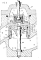
- la figure 2 est une coupe axiale d'une vanne selon l'invention selon une seconde forme de réalisation.
- FIG. 1 is an axial section of a first embodiment of a valve according to the invention, and
- Figure 2 is an axial section of a valve according to the invention according to a second embodiment.
La vanne de régulation 10 illustrée à la figure 1 comporte un corps 11 à passage traversant dans lequel le fluide à commander se déplace d'une entrée 12 à une sortie 13 en passant de la surface extérieure 14 d'une cage cylindrique 15 à la surface intérieure 16 de celle-ci par des ouvertures latérales 17 qui y sont ménagées, et dont la forme et la section sont choisies en fonction de la courbe caractéristique et des performances de la vanne que l'on veut obtenir.The
La cage 15,qui prend appui par son bord inférieur 18 sur un épaulement annulaire 19 présenté par le corps 11 avec interposition d'un joint d'étanchéité 21, s'étend d'abord dans une chambre annulaire 22 ménagée dans le corps, qui est en communication avec l'entrée 12 et en regard des ouvertures 17, puis avec un jeu 23 dans une cheminée cylindrique 24 du corps, jusquau bord supérieur 26 de la cheminée 24 avec lequel un décrochement 25 de son bord supérieur est de niveau. Un joint 27 d'étanchéité est pressé sur le décrochement 25 et le bord 26 par la surface annulaire inférieure 28 d'un chapeau 29 maintenu sur la partie supérieure du corps par des moyens non représentés, et traversé avec interposition de moyens d'étanchéité 31 par une tige de commande 32 coaxiale à l'axe XX' de la cage 15. La partie supérieure de la tige 32, extérieure au corps et au chapeau de la vanne, est reliée à des moyens de déplacements axiaux non représentés, et son extrémité inférieure comporte un renflement cylindrique 33 dont la face inférieure conique 34 reçoit une bille 35 portée par le fond 36 d'un clapet pilote 37 formé d'une partie inférieure 38 et d'une partie supérieure 39 rendues solidaires par vissage et entourrant le renflement 33.The
Le fond 36 est apte, lorsque la tige 32 est déplacée vers le corps 11, à fermer par sa surface plane inférieure venant au contact d'une portée 40, un orifice de passage 41 ménagé dans le fond 42, sensiblement normal à l'axe XX', d'un clapet principal 43 en forme de pot, dont la paroi latérale cylindrique 44 glisse sur la surface interne 16 de la cage 15, la face 45 amont du fond 42, ou face en regard du chapeau 29 étant solidarisée, par des moyens non représentés, au bord inférieur d'une cloche 46.The
La cloche 46, percée de trous latéraux 47 et d'un trou axial 48 recevant la tige 32, entoure le clapet pilote 37, un ressort 49 étant placé entre la face 45 amont du fond 42 et une lèvre annulaire 50 présentée par la partie supérieure 39 du clapet pilote 37 de manière à solliciter le clapet pilote 37 vers le fond de la cloche 46, c'est-à-dire à l'ouberture de l'orifice de passage 41.The
Le clapet principal 43 coiffe un plateau 51 circulaire, disposé sensiblement perpendiculairement à l'axe XX', avec interposition entre la surface interne 52 de la paroi 44 et le plateau 51 d'un joint d'étanchéité 53 logé dans une rainure de la paroi latérale du plateau, ce dernier présentant, à l'opposé de la tige 32, un pied axial 54 solidarisé avec le fond 55 du corps 11 opposé au chapeau 29 grâce à un goujon 57 engagé dans un trou 58 du fond 55 et fixé à ce dernier par un boulon 56.The
Un trou traversant 61 de section Sl est ménagé dans le plateau de manière à faire communiquer la sortie 13 de la vanne avec la chambre aval 62 limitée par la surface supérieure 63 du plateau 51 et la surface inférieure ou aval 64 du fond 42, et un passage traversant 65 est ménagé dans la cage 15 au niveau de la cheminée 24.A through
Le fonctionnement de la vanne qui vient d'être décrite est le suivant :
- Dans l'état fermé de la vanne, qui est celui représenté, la partie périphérique 66 de la tranche aval de la
paroi 44 est au contact d'une portée d'étanchéité 67 ménagée sur la surface interne 16 de lacage 15, en dessous des ouvertures latérales 17, de manière à empêcher tout passage direct du fluide de la chambre annulaire 22 vers lasortie 13, et leclapet pilote 37 porte par sa partie inférieure 38 sur la portée 40 présentée par lasurface 45 dufond 42 autour de l'orifice 41, de manière à empêcher tout passage du fluide de lachambre amont 71 limitée par lechapeau 29, la partie supérieure de lacage 15, et lasurface 45 amont duclapet 43, vers lachambre 62.
- In the closed state of the valve, which is that shown, the
peripheral part 66 of the downstream section of thewall 44 is in contact with asealing surface 67 formed on theinternal surface 16 of thecage 15, belowlateral openings 17, so as to prevent any direct passage of the fluid from theannular chamber 22 to theoutlet 13, and thepilot valve 37 carries by itslower part 38 on the bearing 40 presented by thesurface 45 of thebottom 42 around from theorifice 41, so as to prevent any passage of the fluid from theupstream chamber 71 limited by thecap 29, the upper part of thecage 15, and thesurface 45 upstream of thevalve 43, towards thechamber 62.
Le fluide amont présent à l'entrée 12 se glisse dans le jeu 23 ménagé entre la cage 15 et le corps 11, puis dans le passage 65 pour remplir la chambre 71 et sa pression Pl s'exerce donc sur toute la surface 45, soit directement, soit par l'intermédiaire de la cloche 46 ou du clapet pilote 37.The upstream fluid present at the
Le fluide se trouvant dans la chambre 62 est ramené par l'intermédiaire du trou 61 à la pression aval P2, si bien que c'est sensiblement la différence des pressions P1 - P2 qui s'exerce sur le clapet 43 pour l'appliquer sur la portée 67.The fluid in the
Dans cette configuration également, les à-coups de la pression aval P2 sont filtrés par le trou 61, de section limitée, et seules les forces résultant de la pression s'exerçant sur la surface 72 annulaire interne de la tranche de la paroi 44 qui n'est pas en contact avec la portée 67, de valeur très réduite par rapport à la surface 64, sont transmises par le clapet 43 vers la tige 32.Also in this configuration, the jolts of the downstream pressure P 2 are filtered by the
Dans une variante de réalisation non représentée, le trou 61 comporte un dispositif anti-retour interdisant complètement tout passage brusque du fluide aval dans la chambre 62.In an alternative embodiment not shown, the
Lorsque l'on désire passer en position de régulation, la tige 32 est soulevée, ce qui a d'abord pour effet de libérer l'orifice 41, si bien que le fluide se trouvant dans la chambre 71, sous une pression Pl égale à celle du fluide amont, passe dans la chambre 62, les surfaces 45 et 64 du fond 42 du clapet principal 43 étant alors soumises toutes les deux à la même pression P1.When you want to switch to the regulation position, the
La valeur de la surface 45 étant égale à la somme de celles de la surface 64 et des surfaces 66 et 72, le clapet 43 est alors soumis à une force F axiale dirigée de la tige 32 vers le pied 54, et de valeur sensiblement égale à :
La tige 32 continuant à être soulevée, la force qu'elle exerce par l'intermédiaire du ressort 49 sur le clapet 43 diminue et le ressort reste comprimé jusqu'au moment où la face supérieure du clapet 37 s'applique sur le fond de la cloche 46, ce qui a pour résultat d'entraîner vers le haut le clapet 43 qui suit alors exactement le mouvement de la tige 32 et découvre des rangées successives d'ouvertures latérales 17, libérant ainsi un passage direct de l'entrée 12 vers la sortie 13 pour le fluide à commander.As the
Lorsque le débit du fluide ou la différence de pression P1-P2 a atteint la valeur désirée, le mouvement de 32 est arrêté, et l'on choisit les sections S1, S2 et S3 du trou traversant 61, de l'orifice 41, et du passage 65 ainsi que du jeu 24 de manière que :![]()
![]()
![]()
![]()
Comme précédemment, les variations brusques de la pression P2 n'agissent sur la tige 32 que par l'intermédiaire des surfaces 72 et 66 de la tranche de la paroi 44, surfaces extrêmement réduites par rapport à celle du fond 42.As before, the abrupt variations in pressure P 2 act on the
Dans une seconde forme de réalisation, la vanne comporte (fig.2, les éléments semblables de la figure 1 et de la figure 2 ayant les mêmes références), de manière similaire à la vanne décrite précédemment, un corps 11, un chapeau 29, une tige 32 agissant sur un clapet principal 45 par l'intermédiaire d'un renflement 33, d'un clapet pilote 37, d'une cloche 46, et d'un ressort 49, le fond 42 du clapet 45 présentant un orifice 41 apte à être obturé par le fond 36 du clapet pilote 37, la chambre 71 communiquant avec la chambre 62 par l'intermédiaire de l'ouverture 41 et des ouvertures 47 ménagées dans la cloche 46.In a second embodiment, the valve comprises (FIG. 2, the similar elements in FIG. 1 and in FIG. 2 having the same references), similarly to the valve described above, a
La cage 15 s'applique comme précédemment sur le décrochement annulaire 19 du fond 55 du coprs 11 avec interposition d'un joint d'étanchéité 21 et présente en regard de la chambre 22 une configuration cylindrique axiale dans laquelle sont percées une pluralité de rangées d'ouvertures latérales 17.The
Cependant, contrairement à la réalisation précédente, la cage 15 ne s'étend pas jusqu'au chapeau 29, mais se coude vers l'axe XX' pour former un fond 101 circulaire, à légère cônicité dirigée vers le fond 55 du corps 11, comportant un passage traversant 100 en regard du fond 42, et percé en son centre d'une ouverture de passage d'une entretoise 102 ancrée par son filetage inférieur 103 dans le trou taraudé 58, un boulon 104 étant vissé sur la partie supérieure filetée de l'entretoise 102, qui dépasse du fond 101 vers la chambre 71, de manière à appliquer fermement la cage 15 sur le décrochement 19.However, unlike the previous embodiment, the
Le clapet 43 est logé avec un jeu 23 dans la cheminée 24 du corps 11, et sa paroi 44 s'étend vers le fond 55 du corps 11 dans le volume annulaire 22, en entourant la cage 15, sa surface interne 105 glissant sur la surface externe 106 de la partie cylindrique de cette dernière, avec interposition d'un joint 107 logé dans une rainure annulaire 108 placée au-dessus des ouvertures latérales 17 de la cage 15.The
Le fonctionnement de la vanne qui vient d'être décrite est similaire au fonctionnement de la vanne précédente, le jeu existant entre la paroi 44 et la cheminée 24 jouant le rôle du passage 65, la portée 67 étant ici placée sur la partie inférieure de la surface 106, sous les ouvertures 17.The operation of the valve which has just been described is similar to the operation of the preceding valve, the clearance existing between the
Dans des modes de réalisation non représentés, la surface inférieure du fond 36 du clapet pilote 37 peut être conique ou sphérique.In embodiments not shown, the bottom surface of the
Claims (12)
Priority Applications (1)
| Application Number | Priority Date | Filing Date | Title |
|---|---|---|---|
| AT81402056T ATE12976T1 (en) | 1980-12-23 | 1981-12-23 | REGULATION VALVE AND PILOT CONTROL VALVE. |
Applications Claiming Priority (2)
| Application Number | Priority Date | Filing Date | Title |
|---|---|---|---|
| FR8027267 | 1980-12-23 | ||
| FR8027267A FR2496825A1 (en) | 1980-12-23 | 1980-12-23 | CAGE CONTROL VALVE AND PILOT VALVE |
Publications (2)
| Publication Number | Publication Date |
|---|---|
| EP0055187A1 true EP0055187A1 (en) | 1982-06-30 |
| EP0055187B1 EP0055187B1 (en) | 1985-04-24 |
Family
ID=9249368
Family Applications (1)
| Application Number | Title | Priority Date | Filing Date |
|---|---|---|---|
| EP81402056A Expired EP0055187B1 (en) | 1980-12-23 | 1981-12-23 | Regulation valve and pilot valve |
Country Status (5)
| Country | Link |
|---|---|
| EP (1) | EP0055187B1 (en) |
| AT (1) | ATE12976T1 (en) |
| DE (1) | DE3170213D1 (en) |
| ES (1) | ES8303651A1 (en) |
| FR (1) | FR2496825A1 (en) |
Cited By (1)
| Publication number | Priority date | Publication date | Assignee | Title |
|---|---|---|---|---|
| CN102853154A (en) * | 2012-08-29 | 2013-01-02 | 江阴万讯自控设备有限公司 | High-pressure difference classification protected regulating valve |
Families Citing this family (2)
| Publication number | Priority date | Publication date | Assignee | Title |
|---|---|---|---|---|
| US4679592A (en) * | 1985-10-07 | 1987-07-14 | Teledyne Industries, Inc. | Valve seat design to reduce cavitation |
| US4693270A (en) * | 1986-03-24 | 1987-09-15 | Durabla Manufacturing Co. | Check valve |
Citations (4)
| Publication number | Priority date | Publication date | Assignee | Title |
|---|---|---|---|---|
| FR2121336A5 (en) * | 1971-01-08 | 1972-08-18 | Samson Apparatebau Ag | |
| FR2152151A5 (en) * | 1971-12-10 | 1973-04-20 | Masoneilan Int Inc | |
| US4004613A (en) * | 1975-09-09 | 1977-01-25 | Dresser Industries, Inc. | Flow control valve |
| FR2381219A1 (en) * | 1977-02-16 | 1978-09-15 | Copes Vulcan Inc | ANTIAVITATION VALVE, ESPECIALLY FOR ADJUSTING THE FLOW RATE OF A HIGH PRESSURE LIQUID |
-
1980
- 1980-12-23 FR FR8027267A patent/FR2496825A1/en active Granted
-
1981
- 1981-12-22 ES ES508251A patent/ES8303651A1/en not_active Expired
- 1981-12-23 DE DE8181402056T patent/DE3170213D1/en not_active Expired
- 1981-12-23 EP EP81402056A patent/EP0055187B1/en not_active Expired
- 1981-12-23 AT AT81402056T patent/ATE12976T1/en active
Patent Citations (4)
| Publication number | Priority date | Publication date | Assignee | Title |
|---|---|---|---|---|
| FR2121336A5 (en) * | 1971-01-08 | 1972-08-18 | Samson Apparatebau Ag | |
| FR2152151A5 (en) * | 1971-12-10 | 1973-04-20 | Masoneilan Int Inc | |
| US4004613A (en) * | 1975-09-09 | 1977-01-25 | Dresser Industries, Inc. | Flow control valve |
| FR2381219A1 (en) * | 1977-02-16 | 1978-09-15 | Copes Vulcan Inc | ANTIAVITATION VALVE, ESPECIALLY FOR ADJUSTING THE FLOW RATE OF A HIGH PRESSURE LIQUID |
Cited By (2)
| Publication number | Priority date | Publication date | Assignee | Title |
|---|---|---|---|---|
| CN102853154A (en) * | 2012-08-29 | 2013-01-02 | 江阴万讯自控设备有限公司 | High-pressure difference classification protected regulating valve |
| CN102853154B (en) * | 2012-08-29 | 2014-08-13 | 江阴万讯自控设备有限公司 | High-pressure difference classification protected regulating valve |
Also Published As
| Publication number | Publication date |
|---|---|
| ATE12976T1 (en) | 1985-05-15 |
| ES508251A0 (en) | 1983-02-01 |
| FR2496825A1 (en) | 1982-06-25 |
| EP0055187B1 (en) | 1985-04-24 |
| ES8303651A1 (en) | 1983-02-01 |
| DE3170213D1 (en) | 1985-05-30 |
| FR2496825B1 (en) | 1983-01-28 |
Similar Documents
| Publication | Publication Date | Title |
|---|---|---|
| FR2567615A1 (en) | PILOT MODULATION VALVE WITH PRESSURE CONTROL | |
| EP0185389B1 (en) | Damper for a motor vehicle suspension | |
| CA1065150A (en) | Reducing valve for gas lighter | |
| EP0617974A1 (en) | Implantable drainage valve for the treatment of hydrocephalus | |
| EP0275503A1 (en) | Damper with load compensation | |
| FR3054610B1 (en) | VENTILATION FLOW REGULATOR FOR A PRESSURIZED VEHICLE TANK. | |
| EP0032346A1 (en) | Safety valve having a hydraulic brake | |
| EP0416987A1 (en) | Valve for hydraulic fluid and damper equipped with such a valve | |
| FR2480692A1 (en) | CONTROL DEVICE FOR THE VALVE MECHANISM OF A SERVOFREIN | |
| FR2711201A1 (en) | Shock absorber with variable damping effect depending on the load. | |
| FR2652426A1 (en) | GAS BOTTLE REGULATOR. | |
| EP0037322A1 (en) | Ball valve | |
| EP0055187B1 (en) | Regulation valve and pilot valve | |
| FR2509829A1 (en) | SOLENOID CONTROLLED PRESSURE REGULATOR | |
| FR2894642A1 (en) | SANDWICH CLUTCH WITH DIRECT ACTION | |
| EP0116247B1 (en) | Pressure relief valve with integrated pilot valve | |
| FR2644221A3 (en) | Control valve | |
| FR2543504A1 (en) | PRESSURE LIMIT VALVE FOR COMPRESSED AIR BRAKING SYSTEMS ON MOTOR VEHICLES | |
| EP1265012B1 (en) | Venting valve for conduits for fluid | |
| FR2580774A1 (en) | Safety valve for an enclosure containing a pressurised fluid | |
| EP0615500B1 (en) | Hydraulic control device including a movable valve | |
| EP0118647A1 (en) | Valve for a flushing tank | |
| EP4197316B1 (en) | Self-contained watering device | |
| FR2509827A1 (en) | PRESSURE CONTROL VALVE | |
| FR2778397A1 (en) | FILLING DEVICE FOR LIQUEFIED PETROLEUM GAS TANK |
Legal Events
| Date | Code | Title | Description |
|---|---|---|---|
| PUAI | Public reference made under article 153(3) epc to a published international application that has entered the european phase |
Free format text: ORIGINAL CODE: 0009012 |
|
| AK | Designated contracting states |
Designated state(s): AT BE CH DE FR GB IT LI LU NL |
|
| 17P | Request for examination filed |
Effective date: 19820826 |
|
| ITF | It: translation for a ep patent filed | ||
| GRAA | (expected) grant |
Free format text: ORIGINAL CODE: 0009210 |
|
| AK | Designated contracting states |
Designated state(s): AT BE CH DE FR GB IT LI LU NL |
|
| REF | Corresponds to: |
Ref document number: 12976 Country of ref document: AT Date of ref document: 19850515 Kind code of ref document: T |
|
| REF | Corresponds to: |
Ref document number: 3170213 Country of ref document: DE Date of ref document: 19850530 |
|
| PG25 | Lapsed in a contracting state [announced via postgrant information from national office to epo] |
Ref country code: LU Free format text: LAPSE BECAUSE OF NON-PAYMENT OF DUE FEES Effective date: 19851231 |
|
| PLBE | No opposition filed within time limit |
Free format text: ORIGINAL CODE: 0009261 |
|
| STAA | Information on the status of an ep patent application or granted ep patent |
Free format text: STATUS: NO OPPOSITION FILED WITHIN TIME LIMIT |
|
| 26N | No opposition filed | ||
| PGFP | Annual fee paid to national office [announced via postgrant information from national office to epo] |
Ref country code: AT Payment date: 19861230 Year of fee payment: 6 |
|
| PGFP | Annual fee paid to national office [announced via postgrant information from national office to epo] |
Ref country code: NL Payment date: 19861231 Year of fee payment: 6 |
|
| PG25 | Lapsed in a contracting state [announced via postgrant information from national office to epo] |
Ref country code: AT Effective date: 19871223 |
|
| PG25 | Lapsed in a contracting state [announced via postgrant information from national office to epo] |
Ref country code: LI Effective date: 19871231 Ref country code: CH Effective date: 19871231 Ref country code: BE Effective date: 19871231 |
|
| BERE | Be: lapsed |
Owner name: SEREG S.A. Effective date: 19871231 |
|
| PG25 | Lapsed in a contracting state [announced via postgrant information from national office to epo] |
Ref country code: NL Effective date: 19880701 |
|
| NLV4 | Nl: lapsed or anulled due to non-payment of the annual fee | ||
| GBPC | Gb: european patent ceased through non-payment of renewal fee | ||
| PG25 | Lapsed in a contracting state [announced via postgrant information from national office to epo] |
Ref country code: FR Free format text: LAPSE BECAUSE OF NON-PAYMENT OF DUE FEES Effective date: 19880831 |
|
| REG | Reference to a national code |
Ref country code: CH Ref legal event code: PL |
|
| PG25 | Lapsed in a contracting state [announced via postgrant information from national office to epo] |
Ref country code: DE Effective date: 19880901 |
|
| REG | Reference to a national code |
Ref country code: FR Ref legal event code: ST |
|
| PG25 | Lapsed in a contracting state [announced via postgrant information from national office to epo] |
Ref country code: GB Free format text: LAPSE BECAUSE OF NON-PAYMENT OF DUE FEES Effective date: 19881121 |