EP0055187A1 - Regulationsventil und Pilotsteuerventil - Google Patents
Regulationsventil und Pilotsteuerventil Download PDFInfo
- Publication number
- EP0055187A1 EP0055187A1 EP81402056A EP81402056A EP0055187A1 EP 0055187 A1 EP0055187 A1 EP 0055187A1 EP 81402056 A EP81402056 A EP 81402056A EP 81402056 A EP81402056 A EP 81402056A EP 0055187 A1 EP0055187 A1 EP 0055187A1
- Authority
- EP
- European Patent Office
- Prior art keywords
- valve
- cage
- main valve
- passage
- fluid
- Prior art date
- Legal status (The legal status is an assumption and is not a legal conclusion. Google has not performed a legal analysis and makes no representation as to the accuracy of the status listed.)
- Granted
Links
Images

Classifications
-
- F—MECHANICAL ENGINEERING; LIGHTING; HEATING; WEAPONS; BLASTING
- F16—ENGINEERING ELEMENTS AND UNITS; GENERAL MEASURES FOR PRODUCING AND MAINTAINING EFFECTIVE FUNCTIONING OF MACHINES OR INSTALLATIONS; THERMAL INSULATION IN GENERAL
- F16K—VALVES; TAPS; COCKS; ACTUATING-FLOATS; DEVICES FOR VENTING OR AERATING
- F16K47/00—Means in valves for absorbing fluid energy
- F16K47/08—Means in valves for absorbing fluid energy for decreasing pressure or noise level and having a throttling member separate from the closure member, e.g. screens, slots, labyrinths
Definitions
- the invention relates to a cage control valve and pilot valve, in particular for high pressures and large flow rates.
- a valve of this type is known in which the fluid to be controlled circulates between an inlet and an outlet in lateral openings formed in a cylindrical cage receiving a main flow-adjusting valve, which more or less closes the openings under the effect of 'a control rod connected to the main valve by elastic means.
- the object of the invention is to propose a valve which, while having the advantages of known cage and pilot valve valves, does not have their drawbacks.
- the control valve according to the invention which has a fluid inlet and outlet separated by a cage with transverse openings, and a control rod with a pilot valve driving a main valve capable of sliding on the cage, is characterized in that that it comprises between its outlet and the downstream transverse face of the main valve a fixed separation member.
- the invention provides for a passage between the inlet of the valve and the upstream chamber, and a hole passing through the fixed separation member and connecting the outlet and the downstream chamber bounded by the downstream transverse face of the main valve and the separator.
- a non-return valve is arranged in the through hole, any sudden passage of the downstream fluid towards the downstream chamber and the main valve being then prohibited.
- the section of the through orifice formed in the main valve is much greater than that of the passage between the inlet and the upstream chamber, and the latter itself has a section greater than that of the hole passing through the member. fixed separation.
- the fluid then always tends to flow from. passage towards the orifice then towards the hole, and the main valve is not braked in its movements by the fluid.
- the pressure of the fluid in the upstream chamber which is exerted over the entire cross section of the main valve and which is practically equal to the upstream pressure, is then substantially identical to that which prevails in the downstream chamber, and which is exerted only on a part of this section, the rest being subjected to the action of the downstream fluid, so that the main valve is constantly returned downstream and therefore occupies a stable equilibrium position.
- the fixed separation member is a plate carried by the valve body, the side walls of the main valve, in the form of a pot, sliding between the edge of the plate and the internal surface of the cage. Only the downstream annular section of the cylindrical side wall of the main valve is then subjected directly to the axial pressure forces of the downstream fluid.
- the passage is produced by a hole passing through the cage and communicating with the inlet of the valve by a gap formed between the external wall of the cage and the body of the valve.
- the fixed separation member is constituted by the cage itself, which then comprises a bottom, the side wall of the main valve in the form of a sliding pot between the external surface of the cage and the body of valve.
- the main valve is thus completely removed from the direct action of the downstream fluid.
- the bottom of the cage is bolted to a spacer integral with the valve body, which allows very simple mounting of the cage and eliminates any sealing problem between the latter and the valve body.
- the body is shaped so that in the regulation and closing positions, the external surface of the side wall of the main valve is constantly bathed by the upstream fluid, and a certain clearance constituting said passage is formed between the body and the valve in the open position of the valve.
- the control valve 10 illustrated in FIG. 1 comprises a body 11 with through passage in which the fluid to be controlled moves from an inlet 12 to an outlet 13 passing from the exterior surface 14 of a cylindrical cage 15 to the surface inside 16 thereof by lateral openings 17 which are formed therein, and the shape and section of which are chosen as a function of the characteristic curve and of the performance of the valve which it is desired to obtain.
- a seal 27 is pressed on the recess 25 and the edge 26 by the lower annular surface 28 of a cap 29 held on the upper part of the body by means not shown, and traversed with the interposition of sealing means 31 by a control rod 32 coaxial with the axis XX 'of the cage 15.
- the upper part of the rod 32, outside the body and the cap of the valve, is connected to axial displacement means not shown, and its end lower comprises a cylindrical bulge 33 whose conical lower face 34 receives a ball 35 carried by the bottom 36 of a pilot valve 37 formed by a lower part 38 and an upper part 39 made integral by screwing and surrounding the bulge 33 .
- the bottom 36 is suitable, when the rod 32 is moved towards the body 11, to close by its lower flat surface coming into contact with a bearing 40, a passage orifice 41 formed in the bottom 42, substantially normal to the axis XX ', of a main valve 43 in the form of a pot, the cylindrical side wall 44 of which slides over the internal surface 16 of the cage 15, the face 45 upstream from the bottom 42, or the opposite face of the cap 29 being secured, means not shown, at the lower edge of a bell 46.
- the bell 46 pierced with lateral holes 47 and an axial hole 48 receiving the rod 32, surrounds the pilot valve 37, a spring 49 being placed between the face 45 upstream of the bottom 42 and an annular lip 50 presented by the upper part 39 of the pilot valve 37 so as to urge the pilot valve 37 towards the bottom of the bell 46, that is to say at the opening of the passage orifice 41.
- the main valve 43 covers a circular plate 51, disposed substantially perpendicular to the axis XX ', with interposition between the internal surface 52 of the wall 44 and the plate 51 of a seal 53 housed in a groove in the wall side of the plate, the latter having, opposite the rod 32, an axial foot 54 secured to the bottom 55 of the body 11 opposite the cap 29 by means of a stud 57 engaged in a hole 58 in the bottom 55 and fixed to it last with a bolt 56.
- a through hole 61 of section S1 is formed in the plate so as to communicate the outlet 13 of the valve with the downstream chamber 62 limited by the upper surface 63 of the plate 51 and the lower or downstream surface 64 of the bottom 42, and a through passage 65 is formed in the cage 15 at the level of the chimney 24.
- the fluid in the chamber 62 is brought back via the hole 61 to the downstream pressure P 2 , so that it is substantially the difference in pressures P 1 - P 2 which is exerted on the valve 43 for the '' apply on staff 67.
- the jolts of the downstream pressure P 2 are filtered by the hole 61, of limited section, and only the forces resulting from the pressure exerted on the internal annular surface 72 of the edge of the wall 44 which is not in contact with the bearing surface 67, of very reduced value relative to the surface 64, are transmitted by the valve 43 to the rod 32.
- the hole 61 includes a non-return device completely preventing any sudden passage of the downstream fluid in the chamber 62.
- the rod 32 When you want to switch to the regulation position, the rod 32 is raised, which firstly has the effect of releasing the orifice 41, so that the fluid located in the chamber 71, under a pressure Pl equal to that of the upstream fluid, passes into the chamber 62, the surfaces 45 and 64 of the bottom 42 of the main valve 43 then being both subjected to the same pressure P 1 .
- the valve 43 is then subjected to an axial force F directed from the rod 32 towards the foot 54, and of substantially equal value at : expression in which D e and D i are the external and internal diameters of the wall 44.
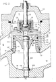
- the valve comprises (FIG. 2, the similar elements in FIG. 1 and in FIG. 2 having the same references), similarly to the valve described above, a body 11, a cap 29, a rod 32 acting on a main valve 45 by means of a bulge 33, a pilot valve 37, a bell 46, and a spring 49, the bottom 42 of the valve 45 having an orifice 41 suitable to be closed off by the bottom 36 of the pilot valve 37, the chamber 71 communicating with the chamber 62 via the opening 41 and the openings 47 formed in the bell 46.
- the cage 15 is applied as previously on the annular step 19 of the bottom 55 of the body 11 with interposition of a seal 21 and has, opposite the chamber 22, an axial cylindrical configuration in which a plurality of rows of lateral openings 17 are pierced.
- the cage 15 does not extend to the cap 29, but bends towards the axis XX ′ to form a circular bottom 101, with slight conicity directed towards the bottom 55 of the body 11, comprising a through passage 100 facing the bottom 42, and pierced in its center with a passage opening of a spacer 102 anchored by its lower thread 103 in the tapped hole 58, a bolt 104 being screwed onto the threaded upper part of the spacer 102, which projects from the bottom 101 towards the chamber 71, so as to firmly apply the cage 15 to the recess 19.
- the valve 43 is housed with a clearance 23 in the chimney 24 of the body 11, and its wall 44 extends towards the bottom 55 of the body 11 in the annular volume 22, surrounding the cage 15, its internal surface 105 sliding on the external surface 106 of the cylindrical part of the latter, with the interposition of a seal 107 housed in an annular groove 108 placed above the lateral openings 17 of the cage 15.
- the bottom surface of the bottom 36 of the pilot valve 37 can be conical or spherical.
Landscapes
- Engineering & Computer Science (AREA)
- General Engineering & Computer Science (AREA)
- Mechanical Engineering (AREA)
- Control Of Fluid Pressure (AREA)
- Fluid-Driven Valves (AREA)
- Details Of Valves (AREA)
- Safety Valves (AREA)
- Feeding And Controlling Fuel (AREA)
- Valve-Gear Or Valve Arrangements (AREA)
- Catching Or Destruction (AREA)
- Fluid-Pressure Circuits (AREA)
Priority Applications (1)
| Application Number | Priority Date | Filing Date | Title |
|---|---|---|---|
| AT81402056T ATE12976T1 (de) | 1980-12-23 | 1981-12-23 | Regulationsventil und pilotsteuerventil. |
Applications Claiming Priority (2)
| Application Number | Priority Date | Filing Date | Title |
|---|---|---|---|
| FR8027267 | 1980-12-23 | ||
| FR8027267A FR2496825A1 (fr) | 1980-12-23 | 1980-12-23 | Vanne de regulation a cage et clapet pilote |
Publications (2)
| Publication Number | Publication Date |
|---|---|
| EP0055187A1 true EP0055187A1 (de) | 1982-06-30 |
| EP0055187B1 EP0055187B1 (de) | 1985-04-24 |
Family
ID=9249368
Family Applications (1)
| Application Number | Title | Priority Date | Filing Date |
|---|---|---|---|
| EP81402056A Expired EP0055187B1 (de) | 1980-12-23 | 1981-12-23 | Regulationsventil und Pilotsteuerventil |
Country Status (5)
| Country | Link |
|---|---|
| EP (1) | EP0055187B1 (de) |
| AT (1) | ATE12976T1 (de) |
| DE (1) | DE3170213D1 (de) |
| ES (1) | ES8303651A1 (de) |
| FR (1) | FR2496825A1 (de) |
Cited By (1)
| Publication number | Priority date | Publication date | Assignee | Title |
|---|---|---|---|---|
| CN102853154A (zh) * | 2012-08-29 | 2013-01-02 | 江阴万讯自控设备有限公司 | 一种高压差分级防护式调节阀 |
Families Citing this family (2)
| Publication number | Priority date | Publication date | Assignee | Title |
|---|---|---|---|---|
| US4679592A (en) * | 1985-10-07 | 1987-07-14 | Teledyne Industries, Inc. | Valve seat design to reduce cavitation |
| US4693270A (en) * | 1986-03-24 | 1987-09-15 | Durabla Manufacturing Co. | Check valve |
Citations (4)
| Publication number | Priority date | Publication date | Assignee | Title |
|---|---|---|---|---|
| FR2121336A5 (de) * | 1971-01-08 | 1972-08-18 | Samson Apparatebau Ag | |
| FR2152151A5 (de) * | 1971-12-10 | 1973-04-20 | Masoneilan Int Inc | |
| US4004613A (en) * | 1975-09-09 | 1977-01-25 | Dresser Industries, Inc. | Flow control valve |
| FR2381219A1 (fr) * | 1977-02-16 | 1978-09-15 | Copes Vulcan Inc | Vanne anticavitation, notamment pour le reglage du debit d'un liquide sous haute pression |
-
1980
- 1980-12-23 FR FR8027267A patent/FR2496825A1/fr active Granted
-
1981
- 1981-12-22 ES ES508251A patent/ES8303651A1/es not_active Expired
- 1981-12-23 DE DE8181402056T patent/DE3170213D1/de not_active Expired
- 1981-12-23 AT AT81402056T patent/ATE12976T1/de active
- 1981-12-23 EP EP81402056A patent/EP0055187B1/de not_active Expired
Patent Citations (4)
| Publication number | Priority date | Publication date | Assignee | Title |
|---|---|---|---|---|
| FR2121336A5 (de) * | 1971-01-08 | 1972-08-18 | Samson Apparatebau Ag | |
| FR2152151A5 (de) * | 1971-12-10 | 1973-04-20 | Masoneilan Int Inc | |
| US4004613A (en) * | 1975-09-09 | 1977-01-25 | Dresser Industries, Inc. | Flow control valve |
| FR2381219A1 (fr) * | 1977-02-16 | 1978-09-15 | Copes Vulcan Inc | Vanne anticavitation, notamment pour le reglage du debit d'un liquide sous haute pression |
Cited By (2)
| Publication number | Priority date | Publication date | Assignee | Title |
|---|---|---|---|---|
| CN102853154A (zh) * | 2012-08-29 | 2013-01-02 | 江阴万讯自控设备有限公司 | 一种高压差分级防护式调节阀 |
| CN102853154B (zh) * | 2012-08-29 | 2014-08-13 | 江阴万讯自控设备有限公司 | 一种高压差分级防护式调节阀 |
Also Published As
| Publication number | Publication date |
|---|---|
| ATE12976T1 (de) | 1985-05-15 |
| ES508251A0 (es) | 1983-02-01 |
| ES8303651A1 (es) | 1983-02-01 |
| FR2496825A1 (fr) | 1982-06-25 |
| EP0055187B1 (de) | 1985-04-24 |
| FR2496825B1 (de) | 1983-01-28 |
| DE3170213D1 (en) | 1985-05-30 |
Similar Documents
| Publication | Publication Date | Title |
|---|---|---|
| FR2567615A1 (fr) | Soupape de modulation pilotee a commande par pression | |
| EP0185389B1 (de) | Dämpfer für Kraftfahrzeugaufhängung | |
| CA1065150A (fr) | Detendeur pour briquet a gaz | |
| EP0349377B1 (de) | Elektrisches Mikro-Umschaltventil mit einer einzigen Membran | |
| EP0617974A1 (de) | Implantierbare Drainage zur Behandlung von Hydrocephalus | |
| EP0275503A1 (de) | Dämpfer mit Lastausgleich | |
| FR3054610B1 (fr) | Regulateur de debit de ventilation pour un reservoir pressurise de vehicule. | |
| EP0416987A1 (de) | Ventil für hydraulische Flüssigkeit und ein mit einem solchen Ventil ausgerüsteter Dämpfer | |
| FR2480692A1 (fr) | Dispositif de commande pour le mecanisme a soupape d'un servofrein | |
| EP0037322A1 (de) | Kugelhahn | |
| EP0055187B1 (de) | Regulationsventil und Pilotsteuerventil | |
| FR2652426A1 (fr) | Detendeur de bouteille de gaz. | |
| FR2509829A1 (fr) | Regulateur de pression a commande par solenoide | |
| FR2894642A1 (fr) | Clapet sandwich a action directe | |
| FR2644221A3 (fr) | Soupape de commande | |
| EP0116247A1 (de) | Sicherheitsventil mit integrierter Pilotsteuerung | |
| FR2543504A1 (fr) | Soupape de limitation de pression pour des systemes de freinage a air comprime sur vehicules automobiles | |
| FR2580774A1 (fr) | Soupape de surete pour enceinte contenant un fluide sous pression | |
| EP1265012A1 (de) | Entlüftungsventil für eine Wasserleitung | |
| EP0615500B1 (de) | Hydraulische lenkvorrichtung mit beweglichem ventil | |
| EP0118647A1 (de) | Hahn für Spülkasten | |
| EP0516528B1 (de) | Sicherheitsventil für den Entlüftungskreislauf eines Kfz-Kraftstoffbehälters | |
| FR2509827A1 (fr) | Vanne a commande par pression | |
| FR2778397A1 (fr) | Dispositif de remplissage pour reservoir de gaz de petrole liquefie | |
| EP1783575B1 (de) | Druckminderungsvorrichtung zur automatischen Regulierung des Nachdrucks eines gasförmigen Fluids |
Legal Events
| Date | Code | Title | Description |
|---|---|---|---|
| PUAI | Public reference made under article 153(3) epc to a published international application that has entered the european phase |
Free format text: ORIGINAL CODE: 0009012 |
|
| AK | Designated contracting states |
Designated state(s): AT BE CH DE FR GB IT LI LU NL |
|
| 17P | Request for examination filed |
Effective date: 19820826 |
|
| ITF | It: translation for a ep patent filed |
Owner name: BARZANO' E ZANARDO MILANO S.P.A. |
|
| GRAA | (expected) grant |
Free format text: ORIGINAL CODE: 0009210 |
|
| AK | Designated contracting states |
Designated state(s): AT BE CH DE FR GB IT LI LU NL |
|
| REF | Corresponds to: |
Ref document number: 12976 Country of ref document: AT Date of ref document: 19850515 Kind code of ref document: T |
|
| REF | Corresponds to: |
Ref document number: 3170213 Country of ref document: DE Date of ref document: 19850530 |
|
| PG25 | Lapsed in a contracting state [announced via postgrant information from national office to epo] |
Ref country code: LU Free format text: LAPSE BECAUSE OF NON-PAYMENT OF DUE FEES Effective date: 19851231 |
|
| PLBE | No opposition filed within time limit |
Free format text: ORIGINAL CODE: 0009261 |
|
| STAA | Information on the status of an ep patent application or granted ep patent |
Free format text: STATUS: NO OPPOSITION FILED WITHIN TIME LIMIT |
|
| 26N | No opposition filed | ||
| PGFP | Annual fee paid to national office [announced via postgrant information from national office to epo] |
Ref country code: AT Payment date: 19861230 Year of fee payment: 6 |
|
| PGFP | Annual fee paid to national office [announced via postgrant information from national office to epo] |
Ref country code: NL Payment date: 19861231 Year of fee payment: 6 |
|
| PG25 | Lapsed in a contracting state [announced via postgrant information from national office to epo] |
Ref country code: AT Effective date: 19871223 |
|
| PG25 | Lapsed in a contracting state [announced via postgrant information from national office to epo] |
Ref country code: LI Effective date: 19871231 Ref country code: CH Effective date: 19871231 Ref country code: BE Effective date: 19871231 |
|
| BERE | Be: lapsed |
Owner name: SEREG S.A. Effective date: 19871231 |
|
| PG25 | Lapsed in a contracting state [announced via postgrant information from national office to epo] |
Ref country code: NL Effective date: 19880701 |
|
| NLV4 | Nl: lapsed or anulled due to non-payment of the annual fee | ||
| GBPC | Gb: european patent ceased through non-payment of renewal fee | ||
| PG25 | Lapsed in a contracting state [announced via postgrant information from national office to epo] |
Ref country code: FR Free format text: LAPSE BECAUSE OF NON-PAYMENT OF DUE FEES Effective date: 19880831 |
|
| REG | Reference to a national code |
Ref country code: CH Ref legal event code: PL |
|
| PG25 | Lapsed in a contracting state [announced via postgrant information from national office to epo] |
Ref country code: DE Effective date: 19880901 |
|
| REG | Reference to a national code |
Ref country code: FR Ref legal event code: ST |
|
| PG25 | Lapsed in a contracting state [announced via postgrant information from national office to epo] |
Ref country code: GB Free format text: LAPSE BECAUSE OF NON-PAYMENT OF DUE FEES Effective date: 19881121 |