EP0055146B1 - Circuit d'asservissement numérique en fonction de la fréquence - Google Patents
Circuit d'asservissement numérique en fonction de la fréquence Download PDFInfo
- Publication number
- EP0055146B1 EP0055146B1 EP81401714A EP81401714A EP0055146B1 EP 0055146 B1 EP0055146 B1 EP 0055146B1 EP 81401714 A EP81401714 A EP 81401714A EP 81401714 A EP81401714 A EP 81401714A EP 0055146 B1 EP0055146 B1 EP 0055146B1
- Authority
- EP
- European Patent Office
- Prior art keywords
- frequency
- digital
- value
- difference
- output
- Prior art date
- Legal status (The legal status is an assumption and is not a legal conclusion. Google has not performed a legal analysis and makes no representation as to the accuracy of the status listed.)
- Expired
Links
- 230000001419 dependent effect Effects 0.000 title description 2
- 238000011144 upstream manufacturing Methods 0.000 claims description 2
- 239000000523 sample Substances 0.000 claims 1
- 230000006870 function Effects 0.000 description 18
- 238000005259 measurement Methods 0.000 description 11
- 238000006243 chemical reaction Methods 0.000 description 3
- 238000010586 diagram Methods 0.000 description 3
- 235000021183 entrée Nutrition 0.000 description 2
- 230000004044 response Effects 0.000 description 2
- 230000001052 transient effect Effects 0.000 description 2
- 230000007774 longterm Effects 0.000 description 1
- 238000004519 manufacturing process Methods 0.000 description 1
- 230000035484 reaction time Effects 0.000 description 1
- 230000001360 synchronised effect Effects 0.000 description 1
- 230000017105 transposition Effects 0.000 description 1
Images

Classifications
-
- H—ELECTRICITY
- H02—GENERATION; CONVERSION OR DISTRIBUTION OF ELECTRIC POWER
- H02P—CONTROL OR REGULATION OF ELECTRIC MOTORS, ELECTRIC GENERATORS OR DYNAMO-ELECTRIC CONVERTERS; CONTROLLING TRANSFORMERS, REACTORS OR CHOKE COILS
- H02P23/00—Arrangements or methods for the control of AC motors characterised by a control method other than vector control
- H02P23/22—Controlling the speed digitally using a reference oscillator, a speed proportional pulse rate feedback and a digital comparator
Definitions
- the present invention relates to a control circuit capable of establishing variable digital information as a function of a difference between a measurement frequency and a set frequency.
- This circuit is intended to be incorporated in a control loop in which the control parameter is a frequency and in which it is desired as much as possible that all the elements are digital and with digital adjustment.
- an attempt has been made to produce a digital regulation loop for the speed of a motor the regulation being made by detecting the speed by a tachometric sensor delivering a frequency proportional to the speed, by comparing this frequency with a set frequency. , and by processing the frequency difference so as to produce a digital value signal which is a function of this difference and which acts on the adjustment of the power applied to the motor (by modifying the angle of attack phase of a triac or conduction duty cycle of a transistor for example).
- the present invention relates more specifically to the servo-control part making it possible to produce a digital output value (directly controlling a power adjustment) as a function of a frequency difference.
- the circuit intended to carry out this function cannot be constituted like most of the regulation circuits by a succession of elements carrying out simply a combination of a proportional function, of an integral function, and of a function derived from the difference frequencies. Indeed, this is the solution that would naturally come to mind if the input quantity was a difference in tensions for example. On the contrary, this is a frequency difference.
- the present invention proposes a combination of elements which, without actually constituting a regulation with proportional integral and derived function and with limitation of the type suggested by the book by Winfried Opplet, nevertheless presents the essential characteristics with the advantage of great structural simplicity.
- This circuit is relatively simple and allows efficient frequency control, with good precision thanks to the integral function performed by the up-down counter, a high response speed thanks to the comparator, and good behavior in transient regimes thanks to the limiter which acts as a stop during too sudden variations in measurement frequency or setpoint.
- the minimum and maximum values of the limiter can be modified by action on an appropriate input of the limiter, the adjustment being made as a function of the set frequency.
- the minimum and maximum values of the limiter can be modified by action on an appropriate input of the limiter, the adjustment being made as a function of the set frequency.
- only two groups of limit values can be provided, one corresponding to high set frequencies, the other corresponding to low set frequencies.
- a synchronization member receiving the measurement frequency and a multiple of the set frequency is provided to synchronize the measurement frequency to this multiple upstream of the up-down counter.
- the coefficients K1 and K2 of the servo are numerically adjustable by action on the logic adder to modify the response of the servo.
- a frequency slaving is used from a tachometer sensor 12 which develops a frequency fx directly proportional to the speed of the motor and from a circuit 14 developing a cosigne frequency fc representing the theoretical speed value to be reached by the motor 10.
- the circuit 14 is for example incorporated into a machine programmer and it delivers a set frequency fc which is a function of the work to be performed by the machine.
- the difference between the measurement and reference frequencies fx and fc is the control regulation parameter.
- This frequency difference fc - fx is processed directly in digital form, without frequency-voltage conversion, to establish a digital adjustment value for a digital power control circuit of the motor 10.
- the motor 10 is supplied through a power transistor and the digital adjustment acts on the conduction duty cycle of the transistor.
- the motor can also be powered through a triac, and the digital setting then acts on the conduction phase angle of the triac.
- the servo circuit proper therefore comprises an up-down counter 16 which receives on a counting input the set frequency fc and on a down-counting input, the measurement frequency fx; the content of the counter therefore represents, at a given instant the time integral of the difference of the frequencies fc and fx.
- the circuit also comprises a frequency comparator 18 which receives on one input the frequency fx and on the other the frequency fc, and which establishes a signal indicating whether the difference in frequencies is positive, negative, or zero.
- the comparator 18 compares the respective periods of fx and fc; it has three outputs corresponding respectively to fc - fx positive, fc - fx negative, or fc - fx null.
- the outputs of the comparator 18, and those of the counter 16 are connected to a logic addition circuit 20, which performs a combination of the digital signals coming from the counter and the digital signals coming from the comparator, combination having the form:
- the coefficients K 1 and K 2 are adjustable digital values
- the output signal from the logic adder 20 is a digital signal representing the sum of an integral function of the difference in the input frequencies and a number essentially dependent on the sign of the frequency deviation.
- the digital output signal of the logic adder 20 is applied to a limiter 22 which closes the signal by higher value and by lower value so as to keep it in a given interval.
- This limitation function takes on its meaning during transient regimes where we do not want an abruptly varying frequency difference to lead to sudden saturation of the servo.
- the output signal limited by the limiter 22 is applied to the power control member 24 of the motor 10.
- the limit values determined by the limiter 22 are in principle fixed but can be modified by an appropriate command.
- two control inputs H, B have been provided, which come from the setpoint development circuit 14 and which make it possible to choose two pairs of different limit values depending on whether the setpoint frequency is large or fabricable: input H allows you to choose one of the pairs of values when the setpoint frequency is high; input B allows you to choose the other pair of values when the set frequency is low.
- the up-down counter must have sufficient capacity to absorb all the possible dynamics of the frequency difference fc - fx integrated during the reaction time of the servo-control to a variation of this difference. It is indeed necessary, that when there is a frequency difference of determined amplitude, this difference has time to return to zero before the capacity of the counter, which integrates the pulses coming from this frequency difference, is exceeded . If this capacity were exceeded, there would indeed be a phenomenon of apparent false setpoint.
- the frequency comparison is carried out on the basis of the measurement frequency fx and of a multiple of the reference frequency fc.
- the coefficients K1 and K2 of the combination function performed by the logic adder 20 are type 2 P coefficients, P being a positive or negative integer.
- the output of logic adder 20 is an output with q binary digits, as is the output of limiter 22; however we can use only the most significant digits of this output to adjust the power transmitted to the motor 10.
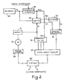
- Figure 2 shows in a slightly more detailed diagram how the frequencies fx and fc are used to establish the desired servo function.
- an oscillator 26 serves to establish a reference frequency FO from which the reference frequency fc is generated.
- a frequency converter receives the frequency FO on the one hand and orders in digital form on the other hand; this converter 28 produces a frequency proportional to the basic frequency FO, the coefficient of proportionality being chosen as a function of the digital orders received.
- the output frequency 28 of the converter is a set frequency, or more exactly it is a multiple of the set frequency itself, that is to say that which represents the speed to be reached by the motor 10.
- the frequency output of the converter 28 can be expressed in the form Afc and it will be further divided by the coefficient A to produce the frequency fc comparable to the measurement frequency fx.
- the frequencies fx and Afc are synchronized in a synchronization circuit 30 in order then to facilitate up and down counting in the counter 16 (in particular to avoid coincidence of up and down count pulses) on the inputs of the counter 16) .
- This synchronization is easy since fx is a frequency much lower than Afc.
- the frequency Afc is divided in the divider 32 and is brought to the counting input of the counter 16, while the frequency fx is brought to the down counting input.
Landscapes
- Engineering & Computer Science (AREA)
- Power Engineering (AREA)
- Control Of Electric Motors In General (AREA)
- Control Of Ac Motors In General (AREA)
Applications Claiming Priority (2)
| Application Number | Priority Date | Filing Date | Title |
|---|---|---|---|
| FR8026416 | 1980-12-12 | ||
| FR8026416A FR2496290A1 (fr) | 1980-12-12 | 1980-12-12 | Circuit d'asservissement numerique en fonction de la frequence |
Publications (2)
| Publication Number | Publication Date |
|---|---|
| EP0055146A1 EP0055146A1 (fr) | 1982-06-30 |
| EP0055146B1 true EP0055146B1 (fr) | 1985-08-14 |
Family
ID=9249006
Family Applications (1)
| Application Number | Title | Priority Date | Filing Date |
|---|---|---|---|
| EP81401714A Expired EP0055146B1 (fr) | 1980-12-12 | 1981-10-27 | Circuit d'asservissement numérique en fonction de la fréquence |
Country Status (3)
| Country | Link |
|---|---|
| EP (1) | EP0055146B1 (OSRAM) |
| DE (1) | DE3171830D1 (OSRAM) |
| FR (1) | FR2496290A1 (OSRAM) |
Families Citing this family (1)
| Publication number | Priority date | Publication date | Assignee | Title |
|---|---|---|---|---|
| JPH01194881A (ja) * | 1988-01-26 | 1989-08-04 | Sony Corp | 記録再生装置 |
Citations (6)
| Publication number | Priority date | Publication date | Assignee | Title |
|---|---|---|---|---|
| NL103155C (OSRAM) * | 1958-06-19 | 1900-01-01 | ||
| DE1742106U (de) * | 1953-12-10 | 1957-03-28 | Siemens Ag | Kathode fuer elektrische entladungsgefaesse. |
| US3243637A (en) * | 1962-10-31 | 1966-03-29 | Gen Electric | Dispenser cathode |
| US3497757A (en) * | 1968-01-09 | 1970-02-24 | Philips Corp | Tungsten dispenser cathode having emission enhancing coating of osmium-iridium or osmium-ruthenium alloy for use in electron tube |
| DE2348617A1 (de) * | 1972-09-28 | 1974-04-04 | Varian Associates | Elektronenstrahlerzeugersystem |
| US4007393A (en) * | 1975-02-21 | 1977-02-08 | U.S. Philips Corporation | Barium-aluminum-scandate dispenser cathode |
Family Cites Families (5)
| Publication number | Priority date | Publication date | Assignee | Title |
|---|---|---|---|---|
| US3546553A (en) * | 1968-09-06 | 1970-12-08 | Nasa | System for maintaining a motor at a predetermined speed utilizing digital feedback means |
| US3646417A (en) * | 1971-03-25 | 1972-02-29 | Ibm | Digital speed servomechanism |
| FR2339202A1 (fr) * | 1976-01-26 | 1977-08-19 | Penet Pierre | Ensemble de commande d'un organe electrique ou hydraulique a fonctionnement periodique et dispositif de mesure du debit d'un fluide incorporant un tel ensemble |
| US4152631A (en) * | 1977-07-26 | 1979-05-01 | Black Body Corporation | Process time control system |
| FR2436434A1 (fr) * | 1978-09-15 | 1980-04-11 | Thomson Csf | Discriminateur de vitesse angulaire et moteur comportant un tel dispositif |
-
1980
- 1980-12-12 FR FR8026416A patent/FR2496290A1/fr active Granted
-
1981
- 1981-10-27 DE DE8181401714T patent/DE3171830D1/de not_active Expired
- 1981-10-27 EP EP81401714A patent/EP0055146B1/fr not_active Expired
Patent Citations (6)
| Publication number | Priority date | Publication date | Assignee | Title |
|---|---|---|---|---|
| DE1742106U (de) * | 1953-12-10 | 1957-03-28 | Siemens Ag | Kathode fuer elektrische entladungsgefaesse. |
| NL103155C (OSRAM) * | 1958-06-19 | 1900-01-01 | ||
| US3243637A (en) * | 1962-10-31 | 1966-03-29 | Gen Electric | Dispenser cathode |
| US3497757A (en) * | 1968-01-09 | 1970-02-24 | Philips Corp | Tungsten dispenser cathode having emission enhancing coating of osmium-iridium or osmium-ruthenium alloy for use in electron tube |
| DE2348617A1 (de) * | 1972-09-28 | 1974-04-04 | Varian Associates | Elektronenstrahlerzeugersystem |
| US4007393A (en) * | 1975-02-21 | 1977-02-08 | U.S. Philips Corporation | Barium-aluminum-scandate dispenser cathode |
Non-Patent Citations (1)
| Title |
|---|
| Winfried Opplet "Kleines Handbuch technischer Regelvorgänge" Verlag Chemie GmbH, 1972, pages 695, 696 * |
Also Published As
| Publication number | Publication date |
|---|---|
| FR2496290A1 (fr) | 1982-06-18 |
| EP0055146A1 (fr) | 1982-06-30 |
| FR2496290B1 (OSRAM) | 1983-11-25 |
| DE3171830D1 (en) | 1985-09-19 |
Similar Documents
| Publication | Publication Date | Title |
|---|---|---|
| EP0199613B1 (fr) | Procédé et dispositif pour commander l'accélération d'un moteur électrique pas à pas | |
| FR2493561A1 (fr) | Controleur de facteur de puissance a etalonnage automatique pour moteurs a induction a courant alternatif | |
| FR2537801A1 (fr) | Systeme d'entrainement d'une generatrice a vitesse constante et appareil de commande de la vitesse d'un arbre | |
| EP0128865A1 (fr) | Procédé pour améliorer l'amortissement à l'arrêt d'un moteur polyphasé, notamment du type pas à pas, et dispositif pour la mise en oeuvre de ce procédé | |
| FR2458796A1 (fr) | Compteur de fluide a turbine a correction et controle automatiques | |
| FR2611894A1 (fr) | Dispositif electronique de mesure d'angle | |
| EP0055146B1 (fr) | Circuit d'asservissement numérique en fonction de la fréquence | |
| FR2509101A1 (fr) | Entrainement electrique a moteur asynchrone | |
| WO1979000808A1 (fr) | Dispositif de mesure de la frequence d'un generateur d'impulsions et systeme de commande numerique comportant un tel dispositif | |
| EP0065901B1 (fr) | Système potentiométrique perfectionné | |
| EP0575911B1 (fr) | Dispositif d'asservissement de la vitesse d'un moteur électrique et son procédé de fonctionnement | |
| EP0197801A2 (fr) | Procédé et dispositif de calage en phase rapide d'un signal d'horloge | |
| FR2591751A1 (fr) | Dispositif d'elaboration d'un signal de tachymetrie de resolution infinie et sans ondulation a partir d'un capteur de position inductif | |
| EP0172071A1 (fr) | Système pour le freinage d'un véhicule, notamment d'un aéronef roulant sur le sol, et régulateur d'antipatinage pour ce système | |
| FR2529674A1 (fr) | Procede et installation de mesure des caracteristiques dynamiques d'un systeme tournant, notamment d'un moteur electrique | |
| FR2576419A1 (fr) | Appareil de detection de la vitesse et du sens de rotation d'un arbre rotatif | |
| EP0105033B1 (fr) | Dispositif pour la commande d'un moteur à courant continu | |
| EP0251908A1 (fr) | Dispositif générateur de signaux à fréquence variable programmable | |
| FR2480191A1 (fr) | Installation pour la commande et la surveillance d'organes de reglage pour machines a imprimer | |
| EP0101773B1 (fr) | Procédé et dispositif de mesure du glissement d'un moteur | |
| FR2585523A1 (fr) | Procede et dispositif de commande de la vitesse et de la position d'au moins un rotor d'un moteur dit esclave en fonction de la vitesse et de la position du rotor d'un moteur dit maitre | |
| CA1199390A (fr) | Dispositif de commande electrique d'une cisaille | |
| EP0227536A1 (fr) | Dispositif de régulation de moteur à combustion, et procédé d'utilisation d'un tel dispositif | |
| EP0201388A1 (fr) | Dispositif de régulation d'un moteur électrique à courant continu et applications à un mesureur d'effort et à un dispositif d'exercice physique | |
| Douet et al. | The use of a safety margin computer for the control of a nuclear power plant |
Legal Events
| Date | Code | Title | Description |
|---|---|---|---|
| PUAI | Public reference made under article 153(3) epc to a published international application that has entered the european phase |
Free format text: ORIGINAL CODE: 0009012 |
|
| AK | Designated contracting states |
Designated state(s): DE FR GB IT NL |
|
| 17P | Request for examination filed |
Effective date: 19820712 |
|
| ITF | It: translation for a ep patent filed | ||
| GRAA | (expected) grant |
Free format text: ORIGINAL CODE: 0009210 |
|
| AK | Designated contracting states |
Designated state(s): DE FR GB IT NL |
|
| REF | Corresponds to: |
Ref document number: 3171830 Country of ref document: DE Date of ref document: 19850919 |
|
| PGFP | Annual fee paid to national office [announced via postgrant information from national office to epo] |
Ref country code: NL Payment date: 19851031 Year of fee payment: 5 |
|
| PLBE | No opposition filed within time limit |
Free format text: ORIGINAL CODE: 0009261 |
|
| STAA | Information on the status of an ep patent application or granted ep patent |
Free format text: STATUS: NO OPPOSITION FILED WITHIN TIME LIMIT |
|
| 26N | No opposition filed | ||
| PG25 | Lapsed in a contracting state [announced via postgrant information from national office to epo] |
Ref country code: NL Effective date: 19870501 |
|
| NLV4 | Nl: lapsed or anulled due to non-payment of the annual fee | ||
| PG25 | Lapsed in a contracting state [announced via postgrant information from national office to epo] |
Ref country code: FR Free format text: LAPSE BECAUSE OF NON-PAYMENT OF DUE FEES Effective date: 19870630 |
|
| GBPC | Gb: european patent ceased through non-payment of renewal fee | ||
| PG25 | Lapsed in a contracting state [announced via postgrant information from national office to epo] |
Ref country code: DE Effective date: 19870701 |
|
| REG | Reference to a national code |
Ref country code: FR Ref legal event code: ST |
|
| PG25 | Lapsed in a contracting state [announced via postgrant information from national office to epo] |
Ref country code: GB Effective date: 19881121 |