EP0055026B1 - Improvements relating to vessels for heating liquids - Google Patents
Improvements relating to vessels for heating liquids Download PDFInfo
- Publication number
- EP0055026B1 EP0055026B1 EP81305460A EP81305460A EP0055026B1 EP 0055026 B1 EP0055026 B1 EP 0055026B1 EP 81305460 A EP81305460 A EP 81305460A EP 81305460 A EP81305460 A EP 81305460A EP 0055026 B1 EP0055026 B1 EP 0055026B1
- Authority
- EP
- European Patent Office
- Prior art keywords
- assembly
- head
- vessel
- clamping
- wall
- Prior art date
- Legal status (The legal status is an assumption and is not a legal conclusion. Google has not performed a legal analysis and makes no representation as to the accuracy of the status listed.)
- Expired
Links
- 238000010438 heat treatment Methods 0.000 title claims description 6
- 239000007788 liquid Substances 0.000 title claims description 5
- 238000007654 immersion Methods 0.000 claims description 32
- 229920003023 plastic Polymers 0.000 claims description 12
- 239000004033 plastic Substances 0.000 claims description 12
- 230000007935 neutral effect Effects 0.000 claims description 6
- 230000002093 peripheral effect Effects 0.000 claims description 4
- 239000004020 conductor Substances 0.000 claims description 3
- 238000000034 method Methods 0.000 claims description 3
- 238000000465 moulding Methods 0.000 description 9
- 230000000712 assembly Effects 0.000 description 4
- 238000000429 assembly Methods 0.000 description 4
- 239000002184 metal Substances 0.000 description 3
- 229910052751 metal Inorganic materials 0.000 description 3
- 238000007789 sealing Methods 0.000 description 3
- 238000013021 overheating Methods 0.000 description 2
- 230000035939 shock Effects 0.000 description 2
- XLYOFNOQVPJJNP-UHFFFAOYSA-N water Substances O XLYOFNOQVPJJNP-UHFFFAOYSA-N 0.000 description 2
- 238000009835 boiling Methods 0.000 description 1
- 238000004140 cleaning Methods 0.000 description 1
- 230000006835 compression Effects 0.000 description 1
- 238000007906 compression Methods 0.000 description 1
- 238000006073 displacement reaction Methods 0.000 description 1
- 238000011065 in-situ storage Methods 0.000 description 1
- 239000011810 insulating material Substances 0.000 description 1
- 230000007774 longterm Effects 0.000 description 1
- 238000004519 manufacturing process Methods 0.000 description 1
Images

Classifications
-
- A—HUMAN NECESSITIES
- A47—FURNITURE; DOMESTIC ARTICLES OR APPLIANCES; COFFEE MILLS; SPICE MILLS; SUCTION CLEANERS IN GENERAL
- A47J—KITCHEN EQUIPMENT; COFFEE MILLS; SPICE MILLS; APPARATUS FOR MAKING BEVERAGES
- A47J27/00—Cooking-vessels
- A47J27/21—Water-boiling vessels, e.g. kettles
- A47J27/21008—Water-boiling vessels, e.g. kettles electrically heated
- A47J27/21058—Control devices to avoid overheating, i.e. "dry" boiling, or to detect boiling of the water
- A47J27/21108—Control devices to avoid overheating, i.e. "dry" boiling, or to detect boiling of the water using a bimetallic element
- A47J27/21116—Control devices to avoid overheating, i.e. "dry" boiling, or to detect boiling of the water using a bimetallic element specially adapted for detecting boiling of the water
-
- H—ELECTRICITY
- H05—ELECTRIC TECHNIQUES NOT OTHERWISE PROVIDED FOR
- H05B—ELECTRIC HEATING; ELECTRIC LIGHT SOURCES NOT OTHERWISE PROVIDED FOR; CIRCUIT ARRANGEMENTS FOR ELECTRIC LIGHT SOURCES, IN GENERAL
- H05B3/00—Ohmic-resistance heating
- H05B3/02—Details
- H05B3/04—Waterproof or air-tight seals for heaters
Definitions
- This invention concerns improvements relating to vessels such as automatic kettles for heating liquids, which vessels are provided with an electrical immersion heater assembly and a switch assembly responsive to overheating of the electrical immersion heater assembly and to boiling of liquid in the vessel to switch off the electrical supply to the immersion heater assembly.
- the steam responsive actuating mechanism extends a considerable vertical distance from adjacent the vent to the head, and is carried on a body of the switch assembly.
- This body also carries the electrical components and is mounted on the head so as to clamp a dry overload actuating mechanism to the head, so that the dry overload actuating mechanism is responsive to overheating of the immersion heater device to actuate the switch contacts.
- the body is an assembly comprising a vertically elongate main moulding (on which the steam responsive actuating mechanism is mounted), and a carrier moulding (on which the electrical components are mounted).
- the carrier moulding can be fitted to the head to enable the immersion heater, dry overload responsive actuating mechanism and electrical components to be tested (prior to being fitted to the vessel and prior to the main moulding being connected to the carrier moulding).
- the skill required to assemble the vessel can be reduced by utilising jigs to pre-align the vessel and immersion heater assembly, or by providing cooperating means on the head and vessel wall to ensure that the head is located properly prior to being secured in position, but such expedients are costly.
- a heater apparatus comprising switch means and an electrical immersion heater having a head adapted to be secured to the wall of a vessel for heating liquids
- the switch means comprises a steam responsive mechanism mounted on a body to form a first assembly, and a second assembly comprising a dry overload responsive actuating mechanism, a switch actuating member and a carrier, on which carrier are mounted live and neutral electrical supply connectors, switch contacts, and conductors to connect electrically the connectors and the switch contacts with cold tails of the immersion heater;
- the second assembly is securable to the head of the immersion heater; and wherein a part of the steam responsive mechanism extends to cooperate with a switch actuating member when the said part and actuating member are in a predetermined mutually relative position so as to be effective to open said contacts when the steam responsive mechanism is subjected to steam;
- the heater apparatus includes clamping means which secures the first assembly to the head independently of the second assembly; in that the clamping is arranged to allow the first assembly to be
- the clamping means preferably comprises a clamping member arranged to engage the head, for clamping the head to the wall of the vessel around an aperture provided in the wall to receive the head.
- the invention also provides heater apparatus as defined above wherein the immersion heater comprises a heating element secured to the head so that cold tails of the element extend through a main panel of the head; wherein the head is provided with an externally threaded cylindrical portion and a peripheral flange around a junction between the main panel and the cylindrical portion; and wherein said main panel has fastener means clamping the second assembly to the main panel.
- the clamping member preferably comprises an internally threaded member engageable around the cylindrical portion, which internally threaded member is provided with an external flange or flanges engageable by at least one clamp abutment member connected to the body, e.g. by fasteners.
- the invention also includes a vessel incorporating the heater apparatus and provides a method assembling a vessel so as to incorporate the heater apparatus, which method includes the steps of fastening the second assembly to the main panel, inserting the immersion heater and second assembly into the vessel and inserting the cylindrical portion through a lower aperture in the wall of the vessel, locating the clamping member on the cylindrical portion and actuating the clamping member to clamp the wall between the flange and the clamping member so that a main part of the element lies in a plane parallel or nearly parallel with a bottom of the vessel; locating the body in a desired position relative to a steam vent in an upper part of said wall, and tightening said plurality of fasteners to clamp the body non-rotatably in the desired position.
- the invention avoids the necessity to align the element with extreme accuracy so as to enable the element to be fitted rapidly to the vessel without requiring the use of jigs or expensive means for aligning the element, and enables the body to be located accurately and rapidly so as to be correctly aligned with the steam vent.
- the correct alignment of the body also facilities the fitting of an outer cover, which latter may form part of or may engage a handle of the vessel.
- the whole of the second assembly in the present invention is protected from working loads, shocks and forces applied to the body either directly or via the cover or handle, so as to improve the reliability of the switch means, and in particular the long term effectiveness of the dry overload responsive actuating mechanism.
- an effective seal can be provided between the clamping means and the second assembly, and the design and production of the carrier is simplified by the invention relieving the carrier of the need to register accurately with and provide mechanical support for the body.
- the switch means is preferably further characterised by the second assembly being removable from the head without releasing the clamping means securing the first assembly to the head.
- the steam responsive mechanism preferably comprises a pivotally mounted lever, and said part of the steam responsive mechanism which extends to overlie and cooperate with the switch actuating member is preferably manually detachable from or displaceable relative to the rest of the layer so as not to overlie the switch actuating member.
- the invention avoids the necessity to re-align the first assembly with the steam vent after the second assembly has been replaced, and maintains the correct alignment of the body so as to facilitate the refitting of an outer cover.
- the outer cover may form part of or may engage a handle of the vessel, and the invention enables the removal of the outer cover to be avoided by utilising a removable plug socket member mounted in the said assembly.
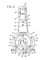
- the electric kettle body has a wall 10 and is provided with a handle 11, an immersion heater 12, an earth pin connector 13 and switch means.
- the switch means comprising a second assembly which includes a dry overload responsive mechanism 14 and an electrical connector and switch arrangement 16; and the switch means further comprises a first assembly which includes a steam responsive actuating mechanism 18.
- the switch means is provided with an outer cover 15 or housing.
- the immersion heater 12 comprises an element 20 having a metal sheath 21; a metal head having a main panel 22, a peripheral rim flange 23 and an externally threaded cylindrical portion 24 perpendicular to the main panel; and an elongate post arrangement.
- the elongate post arrangement comprises a first post 25 which is secured perpendicularly to the main panel above a central axis 26 of the head, and a longer second post 27 secured to the main panel so as to be parallel with and slightly above the post 25.
- the free end parts of the posts are internally threaded to receive two fasteners 30 one of which clamps the earth pin connector 13 directly to the post 27.
- the ends of the sheath 21 are secured to the main panel so as to leave cold tails 28 of the element projecting into a socket defined by the cylindrical portion 24 and the main panel 22, and an intermediate portion of the sheath is secured across one face of the main panel to provide a hot spot 29.
- the immersion heater 12 is secured in a predetermined position in the body by an internally threaded clamping member 31 which is screwed onto the portion 24 so as to clamp the rim and a seal 32 to the wall 10.
- the second assembly may be secured in the socket prior to the immersion heater being fitted to the kettle.
- the dry overload responsive mechanism 14 comprises a moulded member 40 of a heat resistant thermal insulating material, a bimetal 41 of stressed snap-acting dished form located on one side of the member 40 by a cylindrical flanged metal retainer 42, and a push rod 43 which extends perpendicularly from the bimetal through a cylindrical guideway through the member 40 to project from the other side of the member 40.
- the member 40 is apertured to provide passages through which the posts 25 and 27 and cold tails 28 extend, and to receive projections or pegs 60 of the switch arrangement 16.
- Said one side of the member 40 provides a flat abutment face 44 which confronts and abuts the main panel 22, and is shaped to allow the bimetal to snap from a convex dished form to a concave dished form, upon being heated to a predetermined temperature by the hot spot 29, to thrust the push rod 43 away from the hot spot.
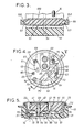
- the electrical connector and switch arrangement 16 comprises a carrier member 61 together with a set of switch contacts, and electrical connectors mounted on the carrier member 61 as shown in Figure 4.
- the connectors comprise a live electrical supply connector terminal pin 62, and a similar neutral pin 63.
- the pin 62 extends through the carrier member and is rivetted over to secure one end of a first spring connector 64 to an inside face 65 of the carrier member. Said one end is further held by a projection 66 of the carrier member.
- the neutral pin 63 similarly extends through the carrier member and is rivetted over to secure a neutral connector 67 to the carrier member, which neutral connector has an extension which is clamped to one of the cold tails 28 by a cylindrical collar 68.
- a second spring connector 69 is secured to the inside face by two projections 70, and similarly has an extension which is secured to the other cold tail 28 by a further collar 68.
- the set of switch contacts comprises a first contact 71, mounted on a free end of the connector 64 and second contact 72 mounted on a free portion of the second spring connector 69.
- the first connector 64 is arranged is shown in Figure 5 so that it can be displayed by the push rod 43 to move the first contact away from the main panel so as to open the contacts
- the second spring connector 69 has an extension 73 which can be moved by an actuating member in the form of a second push rod 74 in a direction towards the main panel so as to open the contacts.
- the spring connectors 64 and 69 are arranged so that when the first contact 71 is moved outwards away from the head, the second contact is prevented from following the first contact for more than a slight distance by the extension 73 abutting either the push rod 74 or the mounting adjacent the push rod; and similarly when the second contact is moved inwards towards the head, any movement of the first contact is restricted by the connector 64 abutting the push rod 43, or optionally an extension 45 of the moulded member 40 (shown in broken lines in Figure 5). Furthermore the contacts are caused to wipe across each other slightly during the initial part of each opening movement and the final part of each closing movement, so as to be self cleaning.
- the inside face of the carrier member and the other side of the moulded member 40 are shaped to interengage and define therebetween a switch contact chamber 75, and the projections 60 are provided with terminal heads, after assembly, to secure together the carrier member and the moulded member 40.
- the peripheral surfaces of the member 40 and an adjacent portion of the carrier member 61 are shaped so as to be a close sliding fit in the socket, and the outside face of the carrier member is provided with a recess 77 and an abutment 76 which enables the carrier member and member 40 to be clamped to the head by the second of the two fasteners 30, independently of the earth pin connector 13 which is partially accommodated in said recess.
- the second push rod 74 of stepped cylindrical form extends through a stepped cylindrical way in the carrier member.
- a plug socket 52 is provided in a plastics member 55 to receive an electrical supply connector (not shown), for connecting to the pins 13, 62 and 63, which pins extend from the carrier member through a wall of the plastics member 55.
- the plastics member 55 is secured to the rear or outside face of the carrier member, e.g. by screws 54, and is recessed adjacent the thrust rod 74 to provide a recess 53.
- the clamping member 31 is grooved internally to receive a sealing ring 51 which engages the periphery of the plastics member 55.
- the steam responsive mechanism 18 is mounted on a body 80, and comprises a lever 81 and a steam responsive member in the form of a steam actuable bimetal 82.
- the body 80 has an upper portion 83 which extends upwards from adjacent the clamping member 31 so as to confront the wall 10 of the kettle body to define a steam space 84 therebetween.
- the bimetal 82 is mounted, at its upper end, on a top part of the upper portion 83 so as to depend within the steam space alongside that side of the upper portion which confronts the wall 10.
- the lever 81 is pivotally mounted by a pivot pin 91 upon the body, and has an upper portion 85 which lies alongside the other side of the upper portion 83. A top part of the portion 85 is engaged by a spring 86.
- the spring is located by the top part of the body, and is arranged so that the lever 81 is movable between a first stable position, in which an adjustable abutment 87 of the lever abuts the upper portion 83, and a second stable position, in which the abutment 87 is spaced apart from the upper portion 83.
- the lever has a ring shaped lower portion 88 on which a detachable abutment part 100 is provided so as to be located in the recess 53. In the first position of the lever, the part 100 is spaced from the second push rod 74, and in the second position the part 100 abuts the push rod so as to hold the contact 72 away from the contact 71.
- the lower portion 88 is of ring form and provides an opening having an internal diameter which is fractionally greater than the overall diameter of the second assembly, and a similar opening is provided in a lower portion 93 of the body.
- the plastics member 55 extends through the openings in the lower portion 88 and in the portion 93 of the body 80, as shown in Figure 1.
- the part 100 comprises a bar which extends along a chord across the lower portion 88.
- the ends 101 of the part 100 are press or snap fitted into sockets 102 in the portion 88 to hold the part 100 in position.
- the upper portion 85 is shaped to provide a knob 90 which projects through the cover 15 to allow the lever to be moved manually to the first position.
- the spring 86 is of round wire formed to S or Z shape so as to have top and bottom parallel limbs which are self centring in V or U shaped confronting grooves 97, 94 in the top parts of the body and lever, which limbs are connected by an intermediate transverse limb, and the arrangement is such that the compression on the spring is increased to a maximum when the lever is in an intermediate position between the first and second positions so as to urge the lever out of said intermediate position.
- the wall 10 has an upper steam vent or hole 33 which allow steam to pass from the kettle into the steam space 84 so as to heat the bimetal 82, whereby to cause the bimetal to bend outwards away from the wall 10 to contact an adjustable abutment 92 on the upper portion 85, which abutment extends through an aperture in the upper portion 83 into the steam space, so that the movement of the bimetal is transmitted to the lever to cause the lever to move to the second position via an unstable intermediate position.
- the lower portion 93 of the body is of ring form and is provided with a forwardly directed annular abutment surface which is adapted to be clamped to an annular abutment face on a rear end portion 34 of the clamping member 31.
- the clamping member 31 forms part of clamping means, which means further comprises clamp abutment ring 35 and clamping fasteners 36.
- the portion 34 extends to within the ring and the clamping member 31 has an external flange 31A to cooperate with an abutment flange 35A of the clamp abutment ring 35.
- the fasteners 36 extend through the portion 93 into the ring 35 so as to be capable of being tightened to thrust the abutment flange 35A against the ftange31Ato drawthe ring 35 towards the portion 93 whereby to thrust the abutment surface of the portion 93 towards and against the abutment face of the clamping member 31.
- the cover 15 is mounted on the body 80 by means of fasteners 57 received in sockets 58 adjacent the upper and lower ends of the body.
- the cover 15 has a lower portion which defines an aperture 50 through which the plastics member 55 extends, and has an upper end portion which fits into a recess 59 in the handle 11 to conceal a fastener 36 used to secure an end of the handle and a baffle 37 to the kettle wall 10.
- the vessel is assembled by assembling, and separately testing, the immersion heater, the first assembly and the second assembly.
- the immersion heater and second assembly may be tested together as a unit prior to the unit being inserted into the kettle.
- the second assembly is then inserted into the head of the immersion heater and the earth pin is inserted and secured in place.
- the immersion heater together with the second assembly is then inserted into the kettle via the opening for the lid of the kettle, and the rear parts of the second assembly and the cylindrical portion 24 of the head are inserted through the lower aperture in the wall 10 until the seal 32 abuts the wall around the aperture.
- the immersion heater 12 is then held so that a major part 20A of the heater 12 lies in a plane which is substantially parallel to the bottom 10A of the kettle, and the head is secured to the wall by means of the threaded clamping member 31, after the sealing ring 51 has been located in the clamping member 31, and after the clamp abutment ring 35 has been located around the clamping member 31.
- the immersion heater is secured in a predetermined position, or in a position which is angularly close to the predetermined position, and the interior of the kettle can be inspected visually to ascertain whether or not the positioning of the immersion heater is acceptable.
- the first assembly is located so that the abutment surface on the lower portion 93 confronts the abutment face on the rear end portion 34 of the clamping member, and is then held whilst the clamping fasteners 36 are inserted into the clamp abutment ring 35.
- the fasteners are then tightened until the clamping means supports the first assembly in such a manner that the first assembly and ring 35 can be moved arcuately relative to the clamping member to allow the upper portion 83 of the body to be moved precisely into a predetermined position relative to the steam vent or hole.
- the clamping fasteners 36 are then fully tightened so that the clamping means secures the first assembly rigidy to the head of the immersion heater and to the wall 10 around the aperture.
- the plastics member 55 and the cover 15 are then located in position and secured by means of the fasteners 54 and 57.
- the top part of the portion 83 preferably extends so as to be locatable in the recess 59 in the handle, or to adjacent the fastener 36, so that the handle or the fastener can be used as a reference point during the arcuate movement of the first assembly about the axis 26 passing centrally through the head some considerable distance below said top part.
- any knocks or bumps applied to the cover 15, and the shock loads generated by the operation of the steam responsive mechanism are transmitted via the body 80 and the clamping member 31 to the wall of the vessel without being imparted to the second assembly, except for the loads applied by the part 100 to the second push rod 74.
- any steam, water or condensate draining down from the steam space 84 will be allowed to drain away around the clamping member 31 and will be prevented from entering the second assembly by the sealing ring 51 and the plastics member 55.
- the part 100 has a considerable area which is available for abutting the push rod 74, which covers an arc about the axis, so that the part 100 can cooperate with the rod not only when said first and second assemblies are in their predetermined positions, but also when the second assembly is in a position which is displaced by several degrees of arc around said axis away from said predetermined position so that the positioning of the immersion heater is no longer critical.
- the second assembly can be removed through the openings in the lower portions of the body 80 and lever 81 and the aperture 50 in the cover 15, after the plastics member 55 has been removed and the part 100 pressed upwards from the sockets 102 and removed from the portion 88.
- the second assembly can thus'be removed for repair, and subsequently replaced, without moving the cover 15 and the body 80, the latter being left in situ together with the bimetal, spring, abutments and lever 80.
- the earth pin may be formed as part of the head instead of being secured to a post on the head, but the arrangement of the earth pin described is preferred because the earth pin is used to centralise the plug socket connector as the latter is inserted into the plug socket.
- the invention has the further advantage that the cover can be made integral with the handle, or, alternatively the cover and the plastics member 55 may be moulded integrally as a single moulding, which can be mounted on the second assembly or the body 80. This single moulding defines the socket 52.
- An alternative adjustable screw abutment 87A may be employed to limit the movement of the lever 81 by engaging the portion 88, the abutment 87 being omitted.
- the push rod 74 may include an arm 74A (indicated in broken lines in Figure 2) which normally depends from the push rod 74 for engagement with and displacement by the lower portion 88, the push rod and arm 74A being rotatable about the axis of the rod in a clockwise direction to swing the arm upwards clear of the portion 88 during removal of the second assembly.
Landscapes
- Engineering & Computer Science (AREA)
- Food Science & Technology (AREA)
- Cookers (AREA)
Priority Applications (1)
| Application Number | Priority Date | Filing Date | Title |
|---|---|---|---|
| AT81305460T ATE14658T1 (de) | 1980-12-19 | 1981-11-19 | Kessel zum erhitzen von fluessigkeiten. |
Applications Claiming Priority (4)
| Application Number | Priority Date | Filing Date | Title |
|---|---|---|---|
| GB8040831A GB2090064B (en) | 1980-12-19 | 1980-12-19 | Electric kettles |
| GB8040831 | 1980-12-19 | ||
| GB8119893 | 1981-06-27 | ||
| GB8119893 | 1981-06-27 |
Publications (2)
| Publication Number | Publication Date |
|---|---|
| EP0055026A1 EP0055026A1 (en) | 1982-06-30 |
| EP0055026B1 true EP0055026B1 (en) | 1985-08-07 |
Family
ID=26277923
Family Applications (1)
| Application Number | Title | Priority Date | Filing Date |
|---|---|---|---|
| EP81305460A Expired EP0055026B1 (en) | 1980-12-19 | 1981-11-19 | Improvements relating to vessels for heating liquids |
Country Status (8)
| Country | Link |
|---|---|
| US (1) | US4455476A (es) |
| EP (1) | EP0055026B1 (es) |
| AU (1) | AU546860B2 (es) |
| CA (1) | CA1179720A (es) |
| DE (1) | DE3171731D1 (es) |
| ES (1) | ES8300256A1 (es) |
| IE (1) | IE52402B1 (es) |
| NZ (1) | NZ198994A (es) |
Families Citing this family (3)
| Publication number | Priority date | Publication date | Assignee | Title |
|---|---|---|---|---|
| GB8618372D0 (en) * | 1986-07-28 | 1986-09-03 | Otter Controls Ltd | Thermal control units |
| FR2868676B1 (fr) * | 2004-04-07 | 2006-06-02 | Seb Sa | Appareil electrique de chauffage de liquide |
| US7706671B2 (en) * | 2005-03-16 | 2010-04-27 | B2M Asset Management, Llc | Multi-function liquid container |
Citations (1)
| Publication number | Priority date | Publication date | Assignee | Title |
|---|---|---|---|---|
| EP2024130A1 (en) * | 2006-05-16 | 2009-02-18 | Pulsar Welding Ltd. | Methods of sealing high pressure vessels using magnetic pulsing with high radial impact speed; vessels manufacturing according such methods |
Family Cites Families (21)
| Publication number | Priority date | Publication date | Assignee | Title |
|---|---|---|---|---|
| CA722290A (en) * | 1965-11-23 | H. Wickenberg Chester | Electrical heating device | |
| US2528191A (en) * | 1948-03-22 | 1950-10-31 | Proctor Electric Co | Cooking device |
| GB1264464A (es) * | 1968-04-18 | 1972-02-23 | ||
| US3539774A (en) * | 1968-07-05 | 1970-11-10 | William H B Thornton | Electrically operated kettles |
| US3725643A (en) * | 1970-01-09 | 1973-04-03 | Hoover Co | Liquid heating units, control means for such units and vessels incorporating heating units |
| GB1340853A (en) * | 1970-01-09 | 1973-12-19 | Hoover Ltd | Liquid heating units control means for such units and vessels incorporating heating units |
| GB1282688A (en) * | 1970-11-25 | 1972-07-19 | Otter Controls Ltd | Improvements in or relating to domestic water boiling appliances |
| GB1383904A (en) * | 1971-02-05 | 1974-02-12 | British Domestic Appliances | Electrically heated vessels |
| NL7206054A (es) * | 1971-05-04 | 1972-11-07 | ||
| GB1408389A (en) * | 1972-09-11 | 1975-10-01 | Hobbs R Ltd | Electric kettles |
| CA980394A (en) * | 1972-09-13 | 1975-12-23 | Leonard K.M. Masters | Electric kettle heating element liquid-tight seal |
| GB1439951A (en) * | 1973-03-28 | 1976-06-16 | Hobbs R Ltd | Electric kettles and electrically-heated beverage makers |
| GB1470366A (en) * | 1973-06-28 | 1977-04-14 | Otter Controls L D | Electric immersion heaters |
| GB2036541B (en) * | 1978-08-17 | 1983-05-11 | Haden Ltd D | Electric kettles |
| GB2035056B (en) * | 1978-08-17 | 1982-11-10 | Haden Ltd D | Electric kettles |
| NZ192597A (en) * | 1979-01-15 | 1982-12-21 | J Taylor | Combined switch-on-dry and steam sensitive protector switch unit for electric water boiling jug |
| GB2040572B (en) * | 1979-01-15 | 1983-08-17 | Taylor J C | Switch units for electric immersion heaters |
| GB2042857B (en) * | 1979-02-01 | 1983-04-13 | Haden Ltd D | Immersion heater assemblies for electric kettles |
| GB2046521B (en) * | 1979-02-09 | 1983-08-03 | Bulpitt & Sons Ltd | Electric kettles |
| GB2045588B (en) * | 1979-03-23 | 1983-09-07 | Taylor J C | Water-boiling containers |
| US4360726A (en) * | 1979-08-15 | 1982-11-23 | D. H. Haden Limited | Electric kettle |
-
1981
- 1981-11-17 IE IE2692/80A patent/IE52402B1/en unknown
- 1981-11-18 NZ NZ198994A patent/NZ198994A/en unknown
- 1981-11-19 EP EP81305460A patent/EP0055026B1/en not_active Expired
- 1981-11-19 DE DE8181305460T patent/DE3171731D1/de not_active Expired
- 1981-11-19 AU AU77659/81A patent/AU546860B2/en not_active Ceased
- 1981-11-20 US US06/323,627 patent/US4455476A/en not_active Expired - Fee Related
- 1981-12-03 CA CA000391448A patent/CA1179720A/en not_active Expired
- 1981-12-09 ES ES507802A patent/ES8300256A1/es not_active Expired
Patent Citations (1)
| Publication number | Priority date | Publication date | Assignee | Title |
|---|---|---|---|---|
| EP2024130A1 (en) * | 2006-05-16 | 2009-02-18 | Pulsar Welding Ltd. | Methods of sealing high pressure vessels using magnetic pulsing with high radial impact speed; vessels manufacturing according such methods |
Also Published As
| Publication number | Publication date |
|---|---|
| ES507802A0 (es) | 1982-11-01 |
| NZ198994A (en) | 1985-11-08 |
| IE812692L (en) | 1982-06-19 |
| US4455476A (en) | 1984-06-19 |
| IE52402B1 (en) | 1987-10-14 |
| EP0055026A1 (en) | 1982-06-30 |
| ES8300256A1 (es) | 1982-11-01 |
| AU546860B2 (en) | 1985-09-26 |
| CA1179720A (en) | 1984-12-18 |
| DE3171731D1 (en) | 1985-09-12 |
| AU7765981A (en) | 1982-06-24 |
Similar Documents
| Publication | Publication Date | Title |
|---|---|---|
| AU659611B2 (en) | Immersion heaters | |
| US4360726A (en) | Electric kettle | |
| GB2102205A (en) | Vessels for heating liquids | |
| US4621186A (en) | Thermally-sensitive control arrangement for containers provided with electric immersion heaters | |
| EP0055026B1 (en) | Improvements relating to vessels for heating liquids | |
| GB2090066A (en) | Electrically heated vessels for liquids | |
| GB2090064A (en) | Electric kettles | |
| CA1174718A (en) | Vessels for heating liquids | |
| GB2170956A (en) | Thermally-sensitive controls for electrical immersion heaters | |
| GB2056828A (en) | Immersion heater assemblies for electric kettles | |
| GB2056777A (en) | Electric kettles | |
| FR2622740A1 (fr) | Disjoncteur en boitier moule comprenant une bilame de precision | |
| GB2056778A (en) | Electric kettles | |
| GB2046521A (en) | Electric kettles | |
| GB2097920A (en) | Thermally-sensitive controls | |
| GB2036541A (en) | Electric kettles | |
| GB2093275A (en) | Switch Assemblies for Electric Kettles | |
| CA1139809A (en) | Switch units for electric immersion heaters | |
| GB2112209A (en) | Thermally-sensitive controls for electric immersion heaters | |
| GB2113010A (en) | Electric immersion heater | |
| GB2204218A (en) | Apparatus for heating liquids | |
| GB2153593A (en) | Temperature sensitive safety switch | |
| GB2111753A (en) | Thermally-sensitive controls for electric heaters | |
| GB2061013A (en) | Electric switches | |
| GB2101877A (en) | Utensils for heating liquids |
Legal Events
| Date | Code | Title | Description |
|---|---|---|---|
| PUAI | Public reference made under article 153(3) epc to a published international application that has entered the european phase |
Free format text: ORIGINAL CODE: 0009012 |
|
| AK | Designated contracting states |
Designated state(s): AT BE CH DE FR GB IT LU NL SE |
|
| 17P | Request for examination filed |
Effective date: 19821120 |
|
| ITF | It: translation for a ep patent filed | ||
| RBV | Designated contracting states (corrected) |
Designated state(s): AT BE CH DE FR IT LI LU NL SE |
|
| GRAA | (expected) grant |
Free format text: ORIGINAL CODE: 0009210 |
|
| AK | Designated contracting states |
Designated state(s): AT BE CH DE FR IT LI LU NL SE |
|
| PG25 | Lapsed in a contracting state [announced via postgrant information from national office to epo] |
Ref country code: AT Effective date: 19850807 |
|
| REF | Corresponds to: |
Ref document number: 14658 Country of ref document: AT Date of ref document: 19850815 Kind code of ref document: T |
|
| PG25 | Lapsed in a contracting state [announced via postgrant information from national office to epo] |
Ref country code: SE Effective date: 19850830 |
|
| REF | Corresponds to: |
Ref document number: 3171731 Country of ref document: DE Date of ref document: 19850912 |
|
| ET | Fr: translation filed | ||
| PG25 | Lapsed in a contracting state [announced via postgrant information from national office to epo] |
Ref country code: LU Free format text: LAPSE BECAUSE OF NON-PAYMENT OF DUE FEES Effective date: 19851130 |
|
| PLBE | No opposition filed within time limit |
Free format text: ORIGINAL CODE: 0009261 |
|
| STAA | Information on the status of an ep patent application or granted ep patent |
Free format text: STATUS: NO OPPOSITION FILED WITHIN TIME LIMIT |
|
| 26N | No opposition filed | ||
| PGFP | Annual fee paid to national office [announced via postgrant information from national office to epo] |
Ref country code: NL Payment date: 19861130 Year of fee payment: 6 |
|
| PG25 | Lapsed in a contracting state [announced via postgrant information from national office to epo] |
Ref country code: BE Effective date: 19871130 |
|
| BERE | Be: lapsed |
Owner name: D.H. HADEN LTD Effective date: 19871130 |
|
| PG25 | Lapsed in a contracting state [announced via postgrant information from national office to epo] |
Ref country code: NL Effective date: 19880601 |
|
| NLV4 | Nl: lapsed or anulled due to non-payment of the annual fee | ||
| PG25 | Lapsed in a contracting state [announced via postgrant information from national office to epo] |
Ref country code: FR Free format text: LAPSE BECAUSE OF NON-PAYMENT OF DUE FEES Effective date: 19880729 |
|
| PG25 | Lapsed in a contracting state [announced via postgrant information from national office to epo] |
Ref country code: DE Effective date: 19880802 |
|
| REG | Reference to a national code |
Ref country code: FR Ref legal event code: ST |
|
| PG25 | Lapsed in a contracting state [announced via postgrant information from national office to epo] |
Ref country code: LI Effective date: 19881130 Ref country code: CH Effective date: 19881130 |
|
| REG | Reference to a national code |
Ref country code: CH Ref legal event code: PL |