EP0054891A2 - Solarmauer und Verfahren zu ihrer Herstellung - Google Patents
Solarmauer und Verfahren zu ihrer Herstellung Download PDFInfo
- Publication number
- EP0054891A2 EP0054891A2 EP81110461A EP81110461A EP0054891A2 EP 0054891 A2 EP0054891 A2 EP 0054891A2 EP 81110461 A EP81110461 A EP 81110461A EP 81110461 A EP81110461 A EP 81110461A EP 0054891 A2 EP0054891 A2 EP 0054891A2
- Authority
- EP
- European Patent Office
- Prior art keywords
- solar
- sheet
- wall
- conduits
- absorber
- Prior art date
- Legal status (The legal status is an assumption and is not a legal conclusion. Google has not performed a legal analysis and makes no representation as to the accuracy of the status listed.)
- Withdrawn
Links
Images
Classifications
-
- B—PERFORMING OPERATIONS; TRANSPORTING
- B32—LAYERED PRODUCTS
- B32B—LAYERED PRODUCTS, i.e. PRODUCTS BUILT-UP OF STRATA OF FLAT OR NON-FLAT, e.g. CELLULAR OR HONEYCOMB, FORM
- B32B5/00—Layered products characterised by the non- homogeneity or physical structure, i.e. comprising a fibrous, filamentary, particulate or foam layer; Layered products characterised by having a layer differing constitutionally or physically in different parts
- B32B5/18—Layered products characterised by the non- homogeneity or physical structure, i.e. comprising a fibrous, filamentary, particulate or foam layer; Layered products characterised by having a layer differing constitutionally or physically in different parts characterised by features of a layer of foamed material
-
- B—PERFORMING OPERATIONS; TRANSPORTING
- B32—LAYERED PRODUCTS
- B32B—LAYERED PRODUCTS, i.e. PRODUCTS BUILT-UP OF STRATA OF FLAT OR NON-FLAT, e.g. CELLULAR OR HONEYCOMB, FORM
- B32B15/00—Layered products comprising a layer of metal
- B32B15/04—Layered products comprising a layer of metal comprising metal as the main or only constituent of a layer, which is next to another layer of the same or of a different material
- B32B15/046—Layered products comprising a layer of metal comprising metal as the main or only constituent of a layer, which is next to another layer of the same or of a different material of foam
-
- B—PERFORMING OPERATIONS; TRANSPORTING
- B32—LAYERED PRODUCTS
- B32B—LAYERED PRODUCTS, i.e. PRODUCTS BUILT-UP OF STRATA OF FLAT OR NON-FLAT, e.g. CELLULAR OR HONEYCOMB, FORM
- B32B3/00—Layered products comprising a layer with external or internal discontinuities or unevennesses, or a layer of non-planar shape; Layered products comprising a layer having particular features of form
- B32B3/26—Layered products comprising a layer with external or internal discontinuities or unevennesses, or a layer of non-planar shape; Layered products comprising a layer having particular features of form characterised by a particular shape of the outline of the cross-section of a continuous layer; characterised by a layer with cavities or internal voids ; characterised by an apertured layer
- B32B3/30—Layered products comprising a layer with external or internal discontinuities or unevennesses, or a layer of non-planar shape; Layered products comprising a layer having particular features of form characterised by a particular shape of the outline of the cross-section of a continuous layer; characterised by a layer with cavities or internal voids ; characterised by an apertured layer characterised by a layer formed with recesses or projections, e.g. hollows, grooves, protuberances, ribs
-
- B—PERFORMING OPERATIONS; TRANSPORTING
- B32—LAYERED PRODUCTS
- B32B—LAYERED PRODUCTS, i.e. PRODUCTS BUILT-UP OF STRATA OF FLAT OR NON-FLAT, e.g. CELLULAR OR HONEYCOMB, FORM
- B32B7/00—Layered products characterised by the relation between layers; Layered products characterised by the relative orientation of features between layers, or by the relative values of a measurable parameter between layers, i.e. products comprising layers having different physical, chemical or physicochemical properties; Layered products characterised by the interconnection of layers
- B32B7/02—Physical, chemical or physicochemical properties
- B32B7/022—Mechanical properties
-
- F—MECHANICAL ENGINEERING; LIGHTING; HEATING; WEAPONS; BLASTING
- F24—HEATING; RANGES; VENTILATING
- F24S—SOLAR HEAT COLLECTORS; SOLAR HEAT SYSTEMS
- F24S20/00—Solar heat collectors specially adapted for particular uses or environments
- F24S20/60—Solar heat collectors integrated in fixed constructions, e.g. in buildings
- F24S20/66—Solar heat collectors integrated in fixed constructions, e.g. in buildings in the form of facade constructions, e.g. wall constructions
-
- Y—GENERAL TAGGING OF NEW TECHNOLOGICAL DEVELOPMENTS; GENERAL TAGGING OF CROSS-SECTIONAL TECHNOLOGIES SPANNING OVER SEVERAL SECTIONS OF THE IPC; TECHNICAL SUBJECTS COVERED BY FORMER USPC CROSS-REFERENCE ART COLLECTIONS [XRACs] AND DIGESTS
- Y02—TECHNOLOGIES OR APPLICATIONS FOR MITIGATION OR ADAPTATION AGAINST CLIMATE CHANGE
- Y02B—CLIMATE CHANGE MITIGATION TECHNOLOGIES RELATED TO BUILDINGS, e.g. HOUSING, HOUSE APPLIANCES OR RELATED END-USER APPLICATIONS
- Y02B10/00—Integration of renewable energy sources in buildings
- Y02B10/20—Solar thermal
-
- Y—GENERAL TAGGING OF NEW TECHNOLOGICAL DEVELOPMENTS; GENERAL TAGGING OF CROSS-SECTIONAL TECHNOLOGIES SPANNING OVER SEVERAL SECTIONS OF THE IPC; TECHNICAL SUBJECTS COVERED BY FORMER USPC CROSS-REFERENCE ART COLLECTIONS [XRACs] AND DIGESTS
- Y02—TECHNOLOGIES OR APPLICATIONS FOR MITIGATION OR ADAPTATION AGAINST CLIMATE CHANGE
- Y02E—REDUCTION OF GREENHOUSE GAS [GHG] EMISSIONS, RELATED TO ENERGY GENERATION, TRANSMISSION OR DISTRIBUTION
- Y02E10/00—Energy generation through renewable energy sources
- Y02E10/40—Solar thermal energy, e.g. solar towers
Definitions
- the present invention refers to a solar wall, i.e. to a wall apt for the realization of civil and industrial buildings and capable of converting the solar energy that is incident on it, into heat stored in a fluid that flows inside conduits made in the wall itself.
- What is also intended as being comprised by the present invention are modular panels that can be placed adjacent to one another so as to give raise to solar walls in civil and industrial buildings in which there are present conduits within which there can be made to flow a fluid that is heated by the solar radiations incident on the modular panels themselves.
- the present invention further refers to a process for manufacturing solar walls and hence also to modular panels for the solar walls forming the object of the present invention.
- One aim of the present invention is to provide a solar wall for civil and/or industrial buildings which does not present the drawbacks of the known solar walls, i.e. which presents a high output of energy transformation, and which is lightweight and also low costing.
- Another aim of the present invention is to provide a process for manufacturing solar walls according to the present invention which process proves to be very simple so as not to cause high costs for the products obtained by this process.
- a further object of the present invention is a process for manufacturing solar walls, characterized by the fact of comprising the phases of:
- the solar wall comprises a laminate formed by a sheet of rigid material for example of metallic material, to one face of which is doubled and joined in a stable way a layer of foam material embedding in correspondence of its one side that is not stably connected to the sheet of rigid material, a solar absorber of the type comprising a slab of elastomeric or plastic material wherein are present a plurality of through-conduits that are parallel to each other and parallel to one side of the slab itself, and two collecting conduits fixed one at each side perpendicular to the through-conduits from which they debouch.
- a covering sheet for the face of the layer of foam material in which the solar absorber is incorporated.
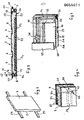
- FIGURES 1 and 2 there is shown a particular form of realization of a solar panel according to the present invention.
- the solar wall 1 comprises, starting from the face 2 of the same, which is intended for being turned towards the inside of the building incorporating the wall, a sheet 3 of rigid material, preferably of metallic material, which therefore is practically inextensible under the effects of tensional stresses which present embossings 4 having a dovetailed shape.
- U-shaped profile 7 which presents at the ends of its legs 8 and 9, where the leg 8 has a width that is greater to that of the leg 9, cantilevered fins lo and 11, respectively, which are parallel to the base 12 of the U-shaped profile 7 and which are turned up in such a way as not to occupy the U-shaped groove of the profile 7.
- a covering sheet 24 of a rigid metallic material that is fixed by its own borders, parallel to the axis of the conduits 22 of the solar absorber 21, to the U-shaped profiles 13 and 16 with known means such as for example nuts, bolts, welding and the like.
- the solar wall 1 is equipped with metallic bodies (not shown) having a dovetailed shape which are apt for fitting in the dovetailed grooves formed by the embossings 4 and therefore made in the sheet 3. of rigid material for forming the connection of the solar wall 1 and with a supporting framework that is represented solely by way of non-limiting example, in FIG. 1 by two beams 25.
- FIG. 3 there is represented in a perspective view and with parts partially removed for pointing out the structure a solar wall according to a variation of the invention.
- the solar wall shown in it differs from that shown in FIG. 2 in that the covering sheet is detached from the face of the solar absorber so as to realize an interspace, and in that there are foreseen means for connecting the said covering sheets spaced apart from the solar absorber.
- the profiles 34 present on the two sides that are parallel to each other in the solar wall, are connected to one another by a pair of rigid material profiles 35, one for each side perpendicular to the conduits 31 of the solar absorber, to which are connected by means known per se spacers 36 on which it rests and to which is connected by known means a slab 37 of a material transparent to light which in not being in contact with the face 29 of the polyurethane layer 28 gives raise to an interspace 38.
- a curved pipe connector 39 one of its ends 4o is inserted in a watertight manner into the cavity of conduit 23, and the other of its ends 41 after having passed through a hole 42 made in the sheet 3 faced towards the inside of the building, and projecting from sheet 3 is connected to conduits (not shown) that connect the solar wall to the circuit of the plant for exploiting the solar energy of which the solar wall forms a component part.
- the curved pipe connectors 39 also carry out an action of mechanically mounting the absorber to the various component parts of the solar wall.
- a sheet of rigid material preferably of metallic material, presenting dovetailed embossings described with reference to FIGURES 2 and 3 and provided on the borders of the sides parallel to said embossings with metallic profiles, is coupled with a solar absorber comprising a slab of elastomeric or plastic material in which there are present conduits extending therethrough in such a way that between them an interspace is formed.
- a solar absorber comprising a slab of elastomeric or plastic material in which there are present conduits extending therethrough in such a way that between them an interspace is formed.
- foamable material and preferably foamable polyurethane Into this interspace there is poured foamable material and preferably foamable polyurethane, and the expansion of said material is carried out, during which phase a bonding between the foam material that assumes the form of a layer, the solar absorber and the previously mentioned sheet of rigid material takes place.
- the solar wall according to the present invention results as being extremely lightweight, seeing that it is constituted substantially by the same foam material which constitutes the thermal insulation of the solar absorber, while the sheet of rigid metallic material that has the function of conferring rigidity to the solar wall, can be of very small thickness and hence it adds only a little to the weight of the solar wall itself.
- the cost of a solar wall according to the invention results as being very low since said solar wall is formed only by the elements necessary for a correct transformation of the energy to which elements are also given the task of acting as structural elements of the wall. Moreover, the manufacturing process of the solar wall is also a very simple one.
- the obtaining of a structure having a considerable rigidity to flexional stresses consents for solving the problem of conferring to a solar wall light weight and a small thickness without any deformation taking place through the effects of the stresses applied.
- a solar wall is subject substantially to stresses lying in its planes having greater dimensions, or in other words, it is subject to buckling loads that tend to laterally flexing the wall itself, even when the load applied is just constituted by the weight of the solar wall itself. It results from this that the achieving of a considerable rigidity in a solar wall according to the present invention allows to increase, even with a wall of an extremely reduced thickness and hence light weight, the buckling load applicable to a solar wall.
Landscapes
- Engineering & Computer Science (AREA)
- Mechanical Engineering (AREA)
- Chemical & Material Sciences (AREA)
- Sustainable Development (AREA)
- Sustainable Energy (AREA)
- Thermal Sciences (AREA)
- Physics & Mathematics (AREA)
- Combustion & Propulsion (AREA)
- Life Sciences & Earth Sciences (AREA)
- General Engineering & Computer Science (AREA)
- Laminated Bodies (AREA)
- Finishing Walls (AREA)
- Building Environments (AREA)
Applications Claiming Priority (2)
| Application Number | Priority Date | Filing Date | Title |
|---|---|---|---|
| IT26719/80A IT1134766B (it) | 1980-12-18 | 1980-12-18 | Parete solare e suo procedimento di fabbricazione |
| IT2671980 | 1980-12-18 |
Publications (2)
| Publication Number | Publication Date |
|---|---|
| EP0054891A2 true EP0054891A2 (de) | 1982-06-30 |
| EP0054891A3 EP0054891A3 (de) | 1982-09-29 |
Family
ID=11220096
Family Applications (1)
| Application Number | Title | Priority Date | Filing Date |
|---|---|---|---|
| EP81110461A Withdrawn EP0054891A3 (de) | 1980-12-18 | 1981-12-15 | Solarmauer und Verfahren zu ihrer Herstellung |
Country Status (5)
| Country | Link |
|---|---|
| EP (1) | EP0054891A3 (de) |
| JP (1) | JPS57129356A (de) |
| ES (1) | ES262512Y (de) |
| IL (1) | IL64593A0 (de) |
| IT (1) | IT1134766B (de) |
Cited By (5)
| Publication number | Priority date | Publication date | Assignee | Title |
|---|---|---|---|---|
| WO2000037861A1 (de) * | 1998-12-22 | 2000-06-29 | Fraunhofer Gesellschaft zur Förderung der angewandten Forschung e.V. | Flächenförmig ausgeführtes fassadenelement zur wärmeenergieaufnahme oder zur wärmeenergieabgabe |
| WO2006058390A1 (en) * | 2004-12-03 | 2006-06-08 | Bluescope Steel Limited | Wall construction |
| AU2005312351B2 (en) * | 2004-12-03 | 2010-06-03 | Bluescope Steel Limited | Wall construction |
| WO2010128081A3 (de) * | 2009-05-05 | 2012-03-08 | Sulfurcell Solartechnik Gmbh | Sonnenenergie nutzendes fassadenelement, eine das fassadenelement umfassende fassade und verfahren zur herstellung einer solchen fassade |
| KR101219103B1 (ko) * | 2004-12-03 | 2013-01-11 | 실리콘 하이브 비.브이. | 프로그래밍 가능한 프로세서, 및 디지털 신호 처리 동작을 수행하는 방법 |
Family Cites Families (6)
| Publication number | Priority date | Publication date | Assignee | Title |
|---|---|---|---|---|
| FR1225760A (fr) * | 1959-02-17 | 1960-07-04 | Pechiney | Appareil destiné à capter l'énergie solaire |
| US3886285A (en) * | 1970-12-07 | 1975-05-27 | Reckitt & Colmann Prod Ltd | Pharmaceutical compositions containing substituted phenyl sulphoxides and sulphones and method of using same |
| JPS53132828A (en) * | 1977-04-22 | 1978-11-20 | Mitsubishi Heavy Ind Ltd | Solar energy collector manufacturing process |
| US4239035A (en) * | 1978-05-24 | 1980-12-16 | The Chemithon Corporation | Solar heating method |
| FR2439854A1 (fr) * | 1978-10-26 | 1980-05-23 | Vermiculite Perlite Sa | Structure isolee par l'exterieur, notamment toiture ou mur, avec circulation d'air sur isolant |
| AT380558B (de) * | 1979-03-06 | 1986-06-10 | Austria Metall | Waermeaustauschende fassadenverkleidung |
-
1980
- 1980-12-18 IT IT26719/80A patent/IT1134766B/it active
-
1981
- 1981-12-15 EP EP81110461A patent/EP0054891A3/de not_active Withdrawn
- 1981-12-18 ES ES1981262512U patent/ES262512Y/es not_active Expired
- 1981-12-18 JP JP56205056A patent/JPS57129356A/ja active Pending
- 1981-12-20 IL IL64593A patent/IL64593A0/xx unknown
Cited By (5)
| Publication number | Priority date | Publication date | Assignee | Title |
|---|---|---|---|---|
| WO2000037861A1 (de) * | 1998-12-22 | 2000-06-29 | Fraunhofer Gesellschaft zur Förderung der angewandten Forschung e.V. | Flächenförmig ausgeführtes fassadenelement zur wärmeenergieaufnahme oder zur wärmeenergieabgabe |
| WO2006058390A1 (en) * | 2004-12-03 | 2006-06-08 | Bluescope Steel Limited | Wall construction |
| AU2005312351B2 (en) * | 2004-12-03 | 2010-06-03 | Bluescope Steel Limited | Wall construction |
| KR101219103B1 (ko) * | 2004-12-03 | 2013-01-11 | 실리콘 하이브 비.브이. | 프로그래밍 가능한 프로세서, 및 디지털 신호 처리 동작을 수행하는 방법 |
| WO2010128081A3 (de) * | 2009-05-05 | 2012-03-08 | Sulfurcell Solartechnik Gmbh | Sonnenenergie nutzendes fassadenelement, eine das fassadenelement umfassende fassade und verfahren zur herstellung einer solchen fassade |
Also Published As
| Publication number | Publication date |
|---|---|
| IL64593A0 (en) | 1982-03-31 |
| IT8026719A0 (it) | 1980-12-18 |
| JPS57129356A (en) | 1982-08-11 |
| ES262512Y (es) | 1983-01-01 |
| ES262512U (es) | 1982-07-01 |
| IT1134766B (it) | 1986-08-13 |
| EP0054891A3 (de) | 1982-09-29 |
Similar Documents
| Publication | Publication Date | Title |
|---|---|---|
| EP1548202B1 (de) | Dämmplatte für Bauzwecke | |
| US4550543A (en) | Construction forms | |
| WO1997018363A1 (en) | Light transmitting roof/floor system | |
| US4212291A (en) | Batten for mounting a unitary solar collector panel | |
| KR20190115655A (ko) | 단열블록을 거푸집 대신 사용하는 콘크리트 구조물 제작틀 및 이의 설치방법 | |
| WO2018009129A1 (en) | A curtain wall system, a composite module for a curtain wall system and a building comprising a curtain wall system | |
| EP0054891A2 (de) | Solarmauer und Verfahren zu ihrer Herstellung | |
| EP2404126B1 (de) | Montageabschnitt für sonnenpaneele | |
| KR20110133203A (ko) | 조립식 지붕의 태양광모듈 지지구 | |
| KR100821971B1 (ko) | 단위패널과 이를 이용한 조립식패널 | |
| CA2165171A1 (en) | Oven module with intermediate expansion joints | |
| US3371457A (en) | Structural part made of plastic material | |
| RU96115922A (ru) | Устройство облицовки поверхности несущей конструкции | |
| KR102415556B1 (ko) | 건물의 마감재로 기능하는 조립형 단위 태양광발전 모듈 및 그 시공방법 | |
| CN113293913B (zh) | 一种装配式吊顶结构及安装方法 | |
| US4505085A (en) | Split panel assembly | |
| EP4312361A1 (de) | Sandwichwandpaneel mit fotovoltaischem paneel und sandwichpaneelsatz | |
| US4558549A (en) | Wall construction prefabricated from interconnectable modules | |
| CN223907669U (zh) | 预组装机电模块单元 | |
| EP0775786A2 (de) | Bausystem für wasser-, luft- und feuerdichte Fassade | |
| JP2964463B2 (ja) | アモルファス太陽電池パネル付きpc部材 | |
| JP3237030B2 (ja) | 仕上げ材の外壁取付構造 | |
| CN113293914B (zh) | 一种具有后置承载结构的装配式吊顶及安装方法 | |
| KR20250161993A (ko) | 간격재가 구비된 모듈러 건축물 | |
| WO2020039423A1 (en) | Adapter for connecting sandwich panels to polycarbonate panels |
Legal Events
| Date | Code | Title | Description |
|---|---|---|---|
| PUAI | Public reference made under article 153(3) epc to a published international application that has entered the european phase |
Free format text: ORIGINAL CODE: 0009012 |
|
| AK | Designated contracting states |
Designated state(s): AT DE FR GB |
|
| PUAL | Search report despatched |
Free format text: ORIGINAL CODE: 0009013 |
|
| AK | Designated contracting states |
Designated state(s): AT DE FR GB |
|
| RHK1 | Main classification (correction) |
Ipc: F24J 3/02 |
|
| 17P | Request for examination filed |
Effective date: 19830224 |
|
| STAA | Information on the status of an ep patent application or granted ep patent |
Free format text: STATUS: THE APPLICATION HAS BEEN WITHDRAWN |
|
| 18W | Application withdrawn |
Withdrawal date: 19831114 |
|
| RIN1 | Information on inventor provided before grant (corrected) |
Inventor name: BROLLO, AURELIO Inventor name: MANCOSU, FEDERICO |