EP0054633B1 - Magnetic clamp for a magnetic tape reel - Google Patents
Magnetic clamp for a magnetic tape reel Download PDFInfo
- Publication number
- EP0054633B1 EP0054633B1 EP81107919A EP81107919A EP0054633B1 EP 0054633 B1 EP0054633 B1 EP 0054633B1 EP 81107919 A EP81107919 A EP 81107919A EP 81107919 A EP81107919 A EP 81107919A EP 0054633 B1 EP0054633 B1 EP 0054633B1
- Authority
- EP
- European Patent Office
- Prior art keywords
- reel
- magnetic
- clamp
- tape
- magnet
- Prior art date
- Legal status (The legal status is an assumption and is not a legal conclusion. Google has not performed a legal analysis and makes no representation as to the accuracy of the status listed.)
- Expired
Links
- 239000002184 metal Substances 0.000 claims description 8
- 230000002411 adverse Effects 0.000 claims description 7
- 230000004907 flux Effects 0.000 description 20
- 230000000694 effects Effects 0.000 description 4
- 230000032258 transport Effects 0.000 description 3
- 230000001133 acceleration Effects 0.000 description 2
- 230000009467 reduction Effects 0.000 description 2
- 239000012141 concentrate Substances 0.000 description 1
- 238000000034 method Methods 0.000 description 1
- 230000008569 process Effects 0.000 description 1
Images
Classifications
-
- G—PHYSICS
- G11—INFORMATION STORAGE
- G11B—INFORMATION STORAGE BASED ON RELATIVE MOVEMENT BETWEEN RECORD CARRIER AND TRANSDUCER
- G11B15/00—Driving, starting or stopping record carriers of filamentary or web form; Driving both such record carriers and heads; Guiding such record carriers or containers therefor; Control thereof; Control of operating function
- G11B15/60—Guiding record carrier
- G11B15/66—Threading; Loading; Automatic self-loading
- G11B15/662—Positioning or locking of spool or reel
-
- G—PHYSICS
- G11—INFORMATION STORAGE
- G11B—INFORMATION STORAGE BASED ON RELATIVE MOVEMENT BETWEEN RECORD CARRIER AND TRANSDUCER
- G11B15/00—Driving, starting or stopping record carriers of filamentary or web form; Driving both such record carriers and heads; Guiding such record carriers or containers therefor; Control thereof; Control of operating function
- G11B15/18—Driving; Starting; Stopping; Arrangements for control or regulation thereof
- G11B15/26—Driving record carriers by members acting directly or indirectly thereon
- G11B15/32—Driving record carriers by members acting directly or indirectly thereon through the reels or cores on to which the record carrier is wound
Definitions
- This invention relates to a magnetic tape reel clamp in combination with a tape reel, according to the precharacterising part of claim 1.
- Magnetic tape transports generally employ a replaceable supply reel and either a fixed or a removable take-up reel.
- Various arrangements have been employed for driving supply and take-up reels and maintaining an appropriate driving relationship between the reel and the motor.
- the reel is held in driving engagement with the motor by means of a magnetic clamp which involves a metal plate attached to the reel hub which is attracted by a suitable magnet means associated with the driving member.
- the acceleration and deceleration forces before substantial and a relatively high clamping force is needed to hold the reel in positive engagement with the driving member during acceleration and deceleration.
- the high clamping force is obtained by a relatively strong magnet which tends to increase the strength of the flux field emanating from the magnet.
- the flux field passes from one pole through the metal plate on the reel hub, back to the other pole of the magnet, and any stray flux that might affect the tape is minimized.
- the stray flux tends to adversely affect the information stored on the magnetic reel if the clamping magnet is too strong.
- the present invention is characterised in that the centre pole is extended above the surface of the magnet and annular lip portion to a point where the strength of the magnetic field is insufficient adversely to affect the condition of the tape on the reel as the reel is placed upon or removed from the clamp.
- the central opening in the metal plate is a close fit upon the extended centre pole to provide a low reluctance shunt path between the centre pole and lip portion through the plate.
- the stray flux field can be better controlled if the centre pole of the annular magnetic holder is extended upward so that as the tape reel is being removed from or inserted onto the drive, the strength of the field, at the point where the centre opening in the plate attached to the tape reel hub surrounds the pole tip, is insufficient to adversely affect the data contained on the magnetic tape. While the strength of the flux field increases closer to the plane of the magnet, the magnetic plate functions as a shunt and prevents stray flux of any strength from reaching the tape, because the field is shunted through the magnetic plate.
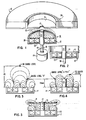
- a tape reel 10 has a single flange and hub on which magnetic tape 26 is wound.
- the reel 10 has, within and attached to the hub, a circular magnetically attractable metal plate 11 with an opening 13 disposed coaxial with the axis of reel 10.
- the reel 10 is driven by a drive motor 14 through a magnetic clamping arrangement 16.
- the clamping arrangement 16 comprises a cup-shaped member 17 which is rotated by motor shaft 18 about an axis 19 and has a circumferentially disposed lip portion 20 and an upstanding centre pole piece 21 extending beyond the lip portion.
- the magnet 22 produces a flux field 25 whose shape is affected by the cup-like member 17 and centre pole piece 21.
- a reel 10 is located on the clamping arrangement 16 with the pole piece 21 extending through the opening 13 (Fig. 2), the plate 11 is attracted and clamped to the edge of the cup-shaped member 17, as shown.
- the strength of the magnetic field 25 provided by magnet 22 determines the clamping force. Where it is desired to have a relatively large clamping force, consideration must be given to the effect that the magnetic field 25 may have on the magnetic condition of the magnetic tape 26 wound on the tape reel 10 as the reel 10 is being removed from or placed on the drive.
- the plane of the metal plate 11 is substantially normal to the axis 19 of revolution of the driving shaft 18 as the reel is moved from its clamped position to its unclamped position.
- Figure 3 illustrates the distribution of the flux density field when a centre pole piece does not extend beyond the edge of the lip portion of the cup-like member.
- Fig. 4 shows the distribution of the flux density field resulting from the extension of centre pole 21, assuming the strength of the magnets are the same.
- the surface area of one pole is increased, which tends to alter the flux density field caused by the axial orientation of magnet 22.
- the effect is to lower the level at which a certain flux density level occurs or, stated differently, the effect is to lower the flux density at a predetermined distance. For example, if the centre pole is lengthened. causing a 65% increase in pole area, the flux density gauss level X at 15 mm from the magnet surface (Fig.
- the annular gap between the centre pole and the opening 13 in the plate 11 is sufficiently small that the plate 11 shunts substantially all of the field from the centre pole horizontally through the plate whence it is returned to the edge of the lip portion 20 of cup-shaped member 17. Substantially all of the field, therefore, acts as a clamping force on the plate 11 and member 17.
- the arrangement disclosed permits a relatively strong magnetic clamping force to be developed by employing a relatively strong magnet without adversely affecting the information recorded on the tape which is wound on the reel to be clamped by the magnetic clamp.
Landscapes
- Unwinding Webs (AREA)
- Winding Of Webs (AREA)
- Iron Core Of Rotating Electric Machines (AREA)
- Manufacturing Of Magnetic Record Carriers (AREA)
Applications Claiming Priority (2)
| Application Number | Priority Date | Filing Date | Title |
|---|---|---|---|
| US06/219,621 US4343441A (en) | 1980-12-24 | 1980-12-24 | Magnetic tape reel clamp with extended center pole |
| US219621 | 1988-07-15 |
Publications (2)
| Publication Number | Publication Date |
|---|---|
| EP0054633A1 EP0054633A1 (en) | 1982-06-30 |
| EP0054633B1 true EP0054633B1 (en) | 1984-03-28 |
Family
ID=22820027
Family Applications (1)
| Application Number | Title | Priority Date | Filing Date |
|---|---|---|---|
| EP81107919A Expired EP0054633B1 (en) | 1980-12-24 | 1981-10-05 | Magnetic clamp for a magnetic tape reel |
Country Status (4)
| Country | Link |
|---|---|
| US (1) | US4343441A (enExample) |
| EP (1) | EP0054633B1 (enExample) |
| JP (1) | JPS57113448A (enExample) |
| DE (1) | DE3162901D1 (enExample) |
Cited By (4)
| Publication number | Priority date | Publication date | Assignee | Title |
|---|---|---|---|---|
| EP0223973A3 (en) * | 1985-11-22 | 1989-04-26 | Fuji Photo Film Co., Ltd. | Method and apparatus for evenly winding magnetic tape |
| EP0232811A3 (en) * | 1986-02-03 | 1989-04-26 | Fuji Photo Film Co., Ltd. | Method and device for winding magnetic tape using magnetic alignment |
| US5640079A (en) * | 1994-08-29 | 1997-06-17 | Andrew Corporation | Battery charger for portable rechargeable batteries |
| WO2001005693A1 (de) | 1999-07-14 | 2001-01-25 | Van Wijk Nederland Bv | Festhaltevorrichtung für räder eines fahrzeuges |
Families Citing this family (15)
| Publication number | Priority date | Publication date | Assignee | Title |
|---|---|---|---|---|
| JPS5761233U (enExample) * | 1980-09-30 | 1982-04-12 | ||
| US4458854A (en) * | 1982-10-15 | 1984-07-10 | International Business Machines Corporation | Magnetic clutch having apparatus for centering magnetic recording tape reel |
| US5261621A (en) * | 1985-11-22 | 1993-11-16 | Fuji Photo Film Co., Ltd. | Method and apparatus for evenly winding magnetic tape |
| US4909455A (en) * | 1986-01-30 | 1990-03-20 | Fuji Photo Film Co., Ltd. | Method and device for winding magnetic tape using magnetic alignment |
| JPS62232788A (ja) * | 1986-04-03 | 1987-10-13 | Fuji Photo Film Co Ltd | 磁気テ−プ巻取方法及び装置 |
| JPS62234286A (ja) * | 1986-04-04 | 1987-10-14 | Fuji Photo Film Co Ltd | 磁気テ−プ巻取方法及び装置 |
| JPH0734558Y2 (ja) * | 1986-04-07 | 1995-08-02 | 富士写真フイルム株式会社 | 磁気テープ巻取装置 |
| JPS6346673A (ja) * | 1986-04-07 | 1988-02-27 | Fuji Photo Film Co Ltd | 磁気テ−プ巻取方法及び装置 |
| US5323984A (en) * | 1992-03-25 | 1994-06-28 | Robert Lackowski | Ferromagnetic insert for use with a magnetic tape cartridge and method of manufacturing the same |
| US5299754A (en) * | 1992-03-25 | 1994-04-05 | Overland Bolling Company | Ferromagnetic insert for use with a magnetic tape cartridge and method of manufacturing the same |
| US5433397A (en) * | 1993-01-04 | 1995-07-18 | Xerox Corporation | High speed tape transport system |
| DE19526913A1 (de) * | 1995-07-24 | 1997-01-30 | Alcatel Kabel Ag | Vorrichtung zum elektromagnetischen Bremsen und Kuppeln einer Spule |
| US5967445A (en) * | 1996-09-20 | 1999-10-19 | Kabushiki Kaisha Yuyama Seisakusho | Method of adjusting tension applied to sheet, and device for the same |
| US6045086A (en) * | 1998-10-02 | 2000-04-04 | Hewlett-Packard Company | Method and apparatus for improved tape packing |
| USD934515S1 (en) * | 2020-12-09 | 2021-10-26 | Just Fur Love, LLC | Clamp for mounting an animal guard |
Family Cites Families (9)
| Publication number | Priority date | Publication date | Assignee | Title |
|---|---|---|---|---|
| US2437997A (en) * | 1945-04-09 | 1948-03-16 | Charlin Andre Marie Bernard | Winding device for cinematograph films and other applications |
| US2598846A (en) * | 1948-08-14 | 1952-06-03 | Indiana Steel Products Co | Fly rod reel |
| US2709051A (en) * | 1951-09-26 | 1955-05-24 | Western Electric Co | Apparatus for coiling filamentary articles |
| US3396919A (en) * | 1966-03-01 | 1968-08-13 | Gen Cable Corp | Magnetic bobbin holding device |
| FR2067523A5 (enExample) * | 1969-11-06 | 1971-08-20 | Pohler Herbert | |
| DE2053940A1 (de) * | 1970-10-28 | 1972-05-04 | Licentia Gmbh | Wickeltellerantrieb, insbesondere für ein Magnetbandgerät |
| JPS4918771Y2 (enExample) * | 1971-08-19 | 1974-05-20 | ||
| DE2648232A1 (de) * | 1976-10-25 | 1978-04-27 | Leopold Ch Schader | Dauermagnetsystem zur beeinflussung biologischer vorgaenge |
| US4327301A (en) * | 1980-05-12 | 1982-04-27 | Dana Corporation | Magnetic clutch housing |
-
1980
- 1980-12-24 US US06/219,621 patent/US4343441A/en not_active Expired - Lifetime
-
1981
- 1981-09-18 JP JP56146427A patent/JPS57113448A/ja active Granted
- 1981-10-05 DE DE8181107919T patent/DE3162901D1/de not_active Expired
- 1981-10-05 EP EP81107919A patent/EP0054633B1/en not_active Expired
Cited By (5)
| Publication number | Priority date | Publication date | Assignee | Title |
|---|---|---|---|---|
| EP0223973A3 (en) * | 1985-11-22 | 1989-04-26 | Fuji Photo Film Co., Ltd. | Method and apparatus for evenly winding magnetic tape |
| EP0232811A3 (en) * | 1986-02-03 | 1989-04-26 | Fuji Photo Film Co., Ltd. | Method and device for winding magnetic tape using magnetic alignment |
| US4844370A (en) * | 1986-02-03 | 1989-07-04 | Fuji Photo Film Co., Ltd. | Method and device for winding magnetic tape using magnetic alignment |
| US5640079A (en) * | 1994-08-29 | 1997-06-17 | Andrew Corporation | Battery charger for portable rechargeable batteries |
| WO2001005693A1 (de) | 1999-07-14 | 2001-01-25 | Van Wijk Nederland Bv | Festhaltevorrichtung für räder eines fahrzeuges |
Also Published As
| Publication number | Publication date |
|---|---|
| JPS57113448A (en) | 1982-07-14 |
| DE3162901D1 (en) | 1984-05-03 |
| EP0054633A1 (en) | 1982-06-30 |
| JPH0243262B2 (enExample) | 1990-09-27 |
| US4343441A (en) | 1982-08-10 |
Similar Documents
| Publication | Publication Date | Title |
|---|---|---|
| EP0054633B1 (en) | Magnetic clamp for a magnetic tape reel | |
| EP0116471A1 (en) | Flexible magnetic discs | |
| US4896232A (en) | Chucking mechanism for floppy disk drive | |
| JPH0721954B2 (ja) | 光学式ディスクプレーヤ | |
| KR870007492A (ko) | 회전 헤드형 자기 기록 재생장치 | |
| US5075809A (en) | Rotary magnetic head tape-scanning device with heads protected from cross-talk by mounting on a head carrier and by annular shielding of a portion of the head projecting from the head carrier | |
| EP0439943A2 (en) | Recording head core yoke with full length core support | |
| US4458854A (en) | Magnetic clutch having apparatus for centering magnetic recording tape reel | |
| EP0661705A2 (en) | Tape drive and cassette with precise registration | |
| US4570254A (en) | Drive motor having moving rotor for compact disc player apparatus | |
| US4812934A (en) | Actuator for memory storage device | |
| US5028012A (en) | Magnetic tape winder | |
| US5243580A (en) | Head for a magneto-optical recording apparatus | |
| US6288853B1 (en) | Optical pickup device | |
| US7194748B2 (en) | Objective lens driver and disk drive device comprising the same | |
| EP0661706B1 (en) | High speed tape transport system | |
| JPH07226050A (ja) | テープカセット | |
| US6914753B2 (en) | Magnetic disk device rotary actuator with magnetic locking | |
| JPH0656687B2 (ja) | 磁気ディスク回転駆動装置のハブ台及びその着磁方法 | |
| KR100249955B1 (ko) | 회전 정보 캐리어 기입 및 판독용 장치 | |
| US6246539B1 (en) | Disk chucking mechanism | |
| EP0232811B1 (en) | Method and device for winding magnetic tape using magnetic alignment | |
| KR100238885B1 (ko) | 자기테이프 권취장치 | |
| JPH0510248Y2 (enExample) | ||
| SU1151414A2 (ru) | Устройство дл доворота шпиндел |
Legal Events
| Date | Code | Title | Description |
|---|---|---|---|
| PUAI | Public reference made under article 153(3) epc to a published international application that has entered the european phase |
Free format text: ORIGINAL CODE: 0009012 |
|
| 17P | Request for examination filed |
Effective date: 19811005 |
|
| AK | Designated contracting states |
Designated state(s): DE FR GB |
|
| GRAA | (expected) grant |
Free format text: ORIGINAL CODE: 0009210 |
|
| AK | Designated contracting states |
Designated state(s): DE FR GB |
|
| REF | Corresponds to: |
Ref document number: 3162901 Country of ref document: DE Date of ref document: 19840503 |
|
| ET | Fr: translation filed | ||
| PLBE | No opposition filed within time limit |
Free format text: ORIGINAL CODE: 0009261 |
|
| STAA | Information on the status of an ep patent application or granted ep patent |
Free format text: STATUS: NO OPPOSITION FILED WITHIN TIME LIMIT |
|
| 26N | No opposition filed | ||
| PGFP | Annual fee paid to national office [announced via postgrant information from national office to epo] |
Ref country code: FR Payment date: 19991018 Year of fee payment: 19 |
|
| PGFP | Annual fee paid to national office [announced via postgrant information from national office to epo] |
Ref country code: GB Payment date: 20001003 Year of fee payment: 20 |
|
| PGFP | Annual fee paid to national office [announced via postgrant information from national office to epo] |
Ref country code: DE Payment date: 20001101 Year of fee payment: 20 |
|
| PG25 | Lapsed in a contracting state [announced via postgrant information from national office to epo] |
Ref country code: FR Free format text: LAPSE BECAUSE OF NON-PAYMENT OF DUE FEES Effective date: 20010629 |
|
| REG | Reference to a national code |
Ref country code: FR Ref legal event code: ST |
|
| PG25 | Lapsed in a contracting state [announced via postgrant information from national office to epo] |
Ref country code: GB Free format text: LAPSE BECAUSE OF EXPIRATION OF PROTECTION Effective date: 20011004 |
|
| REG | Reference to a national code |
Ref country code: GB Ref legal event code: PE20 Effective date: 20011004 |