EP0054569B1 - Ernte- und bergungsmaschine - Google Patents
Ernte- und bergungsmaschine Download PDFInfo
- Publication number
- EP0054569B1 EP0054569B1 EP81902082A EP81902082A EP0054569B1 EP 0054569 B1 EP0054569 B1 EP 0054569B1 EP 81902082 A EP81902082 A EP 81902082A EP 81902082 A EP81902082 A EP 81902082A EP 0054569 B1 EP0054569 B1 EP 0054569B1
- Authority
- EP
- European Patent Office
- Prior art keywords
- truck
- conveyors
- bed
- trucks
- wing
- Prior art date
- Legal status (The legal status is an assumption and is not a legal conclusion. Google has not performed a legal analysis and makes no representation as to the accuracy of the status listed.)
- Expired
Links
- 238000003306 harvesting Methods 0.000 title claims abstract description 35
- 244000037666 field crops Species 0.000 claims abstract description 5
- 230000000087 stabilizing effect Effects 0.000 claims description 4
- 230000000712 assembly Effects 0.000 claims 1
- 238000000429 assembly Methods 0.000 claims 1
- 241000219112 Cucumis Species 0.000 abstract description 17
- 235000015510 Cucumis melo subsp melo Nutrition 0.000 abstract description 17
- 238000000034 method Methods 0.000 abstract description 10
- 235000012828 Citrullus lanatus var citroides Nutrition 0.000 abstract description 7
- 230000007246 mechanism Effects 0.000 abstract description 5
- 235000007688 Lycopersicon esculentum Nutrition 0.000 abstract description 2
- 240000003768 Solanum lycopersicum Species 0.000 abstract description 2
- 235000011299 Brassica oleracea var botrytis Nutrition 0.000 abstract 2
- 240000003259 Brassica oleracea var. botrytis Species 0.000 abstract 2
- 244000291564 Allium cepa Species 0.000 abstract 1
- 235000002732 Allium cepa var. cepa Nutrition 0.000 abstract 1
- 235000021537 Beetroot Nutrition 0.000 abstract 1
- 235000011293 Brassica napus Nutrition 0.000 abstract 1
- 240000007124 Brassica oleracea Species 0.000 abstract 1
- 235000003899 Brassica oleracea var acephala Nutrition 0.000 abstract 1
- 235000011301 Brassica oleracea var capitata Nutrition 0.000 abstract 1
- 235000017647 Brassica oleracea var italica Nutrition 0.000 abstract 1
- 235000001169 Brassica oleracea var oleracea Nutrition 0.000 abstract 1
- 240000008100 Brassica rapa Species 0.000 abstract 1
- 235000000540 Brassica rapa subsp rapa Nutrition 0.000 abstract 1
- 244000241235 Citrullus lanatus Species 0.000 abstract 1
- 240000008067 Cucumis sativus Species 0.000 abstract 1
- 235000009849 Cucumis sativus Nutrition 0.000 abstract 1
- 240000004244 Cucurbita moschata Species 0.000 abstract 1
- 235000009854 Cucurbita moschata Nutrition 0.000 abstract 1
- 235000009852 Cucurbita pepo Nutrition 0.000 abstract 1
- 235000009337 Spinacia oleracea Nutrition 0.000 abstract 1
- 244000300264 Spinacia oleracea Species 0.000 abstract 1
- 235000020354 squash Nutrition 0.000 abstract 1
- 241000219109 Citrullus Species 0.000 description 6
- 230000004048 modification Effects 0.000 description 5
- 238000012986 modification Methods 0.000 description 5
- 230000008569 process Effects 0.000 description 5
- 235000013399 edible fruits Nutrition 0.000 description 4
- 230000007704 transition Effects 0.000 description 3
- 229910000831 Steel Inorganic materials 0.000 description 2
- FJJCIZWZNKZHII-UHFFFAOYSA-N [4,6-bis(cyanoamino)-1,3,5-triazin-2-yl]cyanamide Chemical compound N#CNC1=NC(NC#N)=NC(NC#N)=N1 FJJCIZWZNKZHII-UHFFFAOYSA-N 0.000 description 2
- 230000009471 action Effects 0.000 description 2
- 239000010959 steel Substances 0.000 description 2
- 241000272525 Anas platyrhynchos Species 0.000 description 1
- 239000004809 Teflon Substances 0.000 description 1
- 229920006362 Teflon® Polymers 0.000 description 1
- 230000003466 anti-cipated effect Effects 0.000 description 1
- 230000005540 biological transmission Effects 0.000 description 1
- 230000015556 catabolic process Effects 0.000 description 1
- 238000006243 chemical reaction Methods 0.000 description 1
- 239000011248 coating agent Substances 0.000 description 1
- 238000000576 coating method Methods 0.000 description 1
- 238000010276 construction Methods 0.000 description 1
- 230000008878 coupling Effects 0.000 description 1
- 238000010168 coupling process Methods 0.000 description 1
- 238000005859 coupling reaction Methods 0.000 description 1
- 238000005336 cracking Methods 0.000 description 1
- 239000012530 fluid Substances 0.000 description 1
- 238000009432 framing Methods 0.000 description 1
- 229910052736 halogen Inorganic materials 0.000 description 1
- 150000002367 halogens Chemical class 0.000 description 1
- 238000012787 harvest procedure Methods 0.000 description 1
- 230000013011 mating Effects 0.000 description 1
- 230000009467 reduction Effects 0.000 description 1
- 230000000717 retained effect Effects 0.000 description 1
Images

Classifications
-
- A—HUMAN NECESSITIES
- A01—AGRICULTURE; FORESTRY; ANIMAL HUSBANDRY; HUNTING; TRAPPING; FISHING
- A01D—HARVESTING; MOWING
- A01D67/00—Undercarriages or frames specially adapted for harvesters or mowers; Mechanisms for adjusting the frame; Platforms
-
- A—HUMAN NECESSITIES
- A01—AGRICULTURE; FORESTRY; ANIMAL HUSBANDRY; HUNTING; TRAPPING; FISHING
- A01D—HARVESTING; MOWING
- A01D46/00—Picking of fruits, vegetables, hops, or the like; Devices for shaking trees or shrubs
- A01D46/24—Devices for picking apples or like fruit
- A01D46/243—Accessories specially adapted for manual picking, e.g. ladders, carts
-
- Y—GENERAL TAGGING OF NEW TECHNOLOGICAL DEVELOPMENTS; GENERAL TAGGING OF CROSS-SECTIONAL TECHNOLOGIES SPANNING OVER SEVERAL SECTIONS OF THE IPC; TECHNICAL SUBJECTS COVERED BY FORMER USPC CROSS-REFERENCE ART COLLECTIONS [XRACs] AND DIGESTS
- Y10—TECHNICAL SUBJECTS COVERED BY FORMER USPC
- Y10S—TECHNICAL SUBJECTS COVERED BY FORMER USPC CROSS-REFERENCE ART COLLECTIONS [XRACs] AND DIGESTS
- Y10S56/00—Harvesters
- Y10S56/02—Methods
Definitions
- the present invention was developed particularly toward the specific needs of watermelon har- vecring, and the description will pertain principally to watermelons although the machine and system is equally usable, and will be used, on other field crops.
- Watermelons are currently harvested and taken to the freight depot as follows.
- field laborers called “cutters” move through the fields, locating all ripe melons and cutting their vines and turning them with the yellow side up so that the pickers will known which ones to pick.
- an open truck is driven through roads that are put in the fields between every group of ten rows and field laborers lift the melons into the truck. This is done by the field laborer furthest from the truck picking up the melon in his part of the melon patch and throwing it to the next field hand, so that a bucket- brigade chain is formed, the last link of which is a worker in the truck bed who puts it in the open bed.
- US-A-2647525 discloses a vehicle provided with wing conveyors on which crops are loaded from the fields. The crops are conveyed to other conveying means on the vehicle where grading and other operations take place.
- US-A-4203697 discloses a palletised transfer system for transferring pallets from an agricultural vehicle to another vehicle for shuttling the pallets to a delivery station.
- the present invention provides a system for rapid harvesting and grading of crops on one truck and transfer to other vehicles for shuttling of crops to a delivery station, in which the same basic trucks can be used for both purposes by means of an apparatus adapting one of the trucks for harvesting purposes.
- the invention permits ready conversion of another truck, if the adapted truck should break down.
- the harvesting system utilizes several trucks which are modified in one case to be a harvester truck and in other cases to be shuttle trucks.
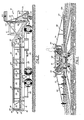
- Figures 1 through 3 illustrate in detail the basic truck 11 to which the appurtenant structure is mounted to convert it into a harvester truck 10.
- the truck 10 has a long, flat bed 12, a cab 14 and a front bumper 16, with the bulk of the appurtenant structure converting it to a harvester being mounted to either the flat bed 12 or the bumper 16.
- the structure mounted to the framework which is in turn mounted to the front bumper pertains to the conveyor mechanism utilized for transporting melons from the fields to the sorting conveyors, and the sorting conveyor together with the off-loading structure are mounted to the truck bed.
- the truck bed mounted portion of the harvester and its operation will be described first.
- a roller grid is permanently mounted to the bed of the truck and in the disclosed embodiment comprises several longitudinal stringer beams 20 between pairs of which are axled rollers 21, the central roller being wider than the others to span the inner edges of two overlying pallets.
- the roller grid which can be seen between containers in Figure 3, may be permanently attached to the truck bed because it is used both in the beds of the harvester truck and the shuttle trucks.
- the trucks used for harvesting and for shuttle trucks are carefully maintained the same except for removable structure so that they may be interchanged in the case of a breakdown of the harvester truck.
- Elevated along both sides of the harvester truck bed are a pair of sorting conveyors 22 which can best be seen in use in Figure 1. These conveyors are supported on two basic framing members 24 and 25. Frame structure 24 is best seen in Figure 17 and frame 25 is shown in Figure 16.
- the sorting conveyors are each removably attached to the bed 18 of the truck and underlying support beams 26 as shown in Figures 16 and 17, with the stake pockets 28 in the truck bed receiving studs 29 and 31 depending from the frame structures.
- Angular support is provided by a brace 30 provided by each of the frames 24 and bolted to the beam 26.
- Duck boards 32 are bolted to the frame structure to provide a standing area for workers who are loading melons (or other crops) from the sorting conveyors into the containers 34, and guides 35 to ensure smooth unloading of the containers.
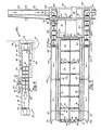
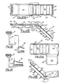
- This structure includes a pair of eyelets 36 which are removably bolted to the rear of the harvesting truck as seen in Figures 11 and 13.
- the eyelets are used to releasably engage the connector pins of an A-shaped stabilizing bar 40 having an outer eyelet 42 which engages the hook 38, removably bolted to the rear of the shuttle truck to steady it and mate the two trucks together during the transfer process about to be described.
- FIG. 1 Other structures are the hinge plates 44 mounted to the back of the truck bed as seen in Figure 1 into which a bridge gate 46 as seen in Figure 2 is attached when the truck in question is used as the harvesting truck.
- the bridge gate has a roller grid covering its top.
- the receiver, or shuttle trucks are the same basic truck as the harvesting truck and may have the mounting parts for the harvesting appurtenances built in, but otherwise have none of the harvesting superstructure except for the roller grid.
- a winch 50 is mounted at the front of the truck bed, operative on a cable 52 with a T-bar 54 at the end.
- a laniard 56 is entrained between the two rows of containers from front to back with a loop at the back which engages the T-bar 54 as shown in Figure 11 at the loading site. Note in Figure 11 the attachment of the stabilizing bar 40 over the hook 38 and the deployment of the bridge gate 46 to define a continuous roller grid in and. between both mated trucks.
- the T-bar is drawn between the containers 34 and engaged in a brace 58 detailed in Figure 12.
- the brace spans both of the pallets 60 as shown in Figure 13, the winch is activated, and the pallets are drawn off in a single motion as shown in Figure 4, transferring the entire pallet load at once.
- Both trucks have a stop 61 mounted to the bed to establish delineate the forwardmost positions of the containers. Note the T-bar, container and pallet above the truck in Figure 4, indicating that when the shuttle truck returns to the field it must bring a fresh supply of pallets and containers, plus one brace 58 to replace those removed during the last trip.
- the original brace which was used to transfer the pallets is retained with the shuttle truck to securely hold the containers in place as they are transported to the shipping depot. Once the trucks are disengaged, the bridge gate 48 and the bar 40 may be elevated into their out-of-the-way position shown in Figure 2.
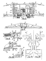
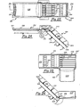
- this structure comprises wing conveyors 62, which bring the fruit adjacent the truck, and elevator conveyors 64 which lift the fruit from the wing conveyors to the sorting conveyors.
- Most of the structure is supported on a forward frame 66 which is mounted on the front bumper 16.
- the forward frame includes an upper crossbeam 68, a pair of uprights 70, another crossbeam directly below beam 68 which is not visible in the drawings but which passes across the top of the bumper 16 and is mounted to the bumper by means of flanges 72 bolted to the bumper, and various other beams and arms extend from the basic forward frame 66 to support the different components of the apparatus.
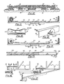
- the wing conveyors are best seen fully extended in Figure 1. These conveyors are supported by cables 74 which pass through pulleys 76 supported on a vertical pivot rod 78 pivotally mounted in brackets 80 to the upright frame members 70. The inboard end of these cables are each connected to a hydraulic cylinder 82. Near the end of each of the wing conveyors is a height sensor 84 which automatically operates an electric valve mechanism, not shown, to control the hydraulic cylinder 82 and ensure the wing. conveyors do not get too high or too low over the fields. This action is illustrated in Figure 6.
- the automatic control feature can be overridden by a manual control, which is one of the controls in the hydraulic console 86, which is mounted to the side of the truck cab 14 to be accessible to the operator.
- the structure of the wing conveyor is representative of the other conveyors, and it will be the only one described in detail in the Specification.
- the duplicated parts of the sorter and wing conveyors are numbered identically.
- basically the wing conveyor comprises a box-shaped frame having four longitudinal corner spars 100 maintained in position at the sides and bottom of the conveyor by spaced supports 102.
- a shaped belt bed 104 attached between the entire length of the top spars is concave in.cross section as can be seen in Figure 14, and thus supports the belt 106 in this shape.
- At the ends of the conveyors are terminal rollers 108, and the return portion of the belt, shown at 110, is supported by spaced return roiiers 112.
- a hydraulic motor 114 At the inboard end of the conveyor is a hydraulic motor 114 whieh belt-drives the inner terminal roller 108 as shown in Figure 15.
- the motor 114 is driven by hydraulic hoses, not shown, connecting the motor to shaft-driven electrical clutch pump 116 and returning fluid through return line 117 to hydraulic return tank 118.
- All of the conveyors and the other hydraulic structures are powered in the same fashion and are controlled either automatically as described, or otherwise at the control console 86, and all conveyor belt support surfaces are coated with Teflon or other antifriction coating 154.
- the transition between the wing conveyors 62 and the elevator conveyors 64 is made in a "turn box" 120, which is basically a curved ramp leading from the inboard edge of the wing conveyor to the bottom of the elevator conveyor.
- the floor slopes downwardly so that melons or other fruit introduced into the turn box will roll to the bottom, where they are picked up by the cleats 122 of the elevator conveyor belt 124.
- the turn box may be seen in Figures 3, 8, 9 and 21 (a) and (b).
- the elevators have a pair of side walls 126 with a belt support floor 128.
- the elevator is bolted to the forward frame 66 at its bottom and at an intermediate position is bolted to the diagonal support brace 130 connected between crossbar 132 (of which there are two) mounted to the truck bed and the upper crossbar 68 of the forward frame.
- the upper end of the elevator is braced against the frame of the sorting conveyor and at this end a hydraulic motor 131 drives the upper terminal roller 137 of the elevator and also the forward roller 140 of the sorting conveyor.
- auxiliary transmission 142 is positioned in the drive train having three shift ratios enables the speed of the truck to be dropped to as little as 30' a minute, as compared with 65' a minute, which is the minimum for the truck without modification.
- Figures 23. and 24 indicate a plurality of sub- . divided cleats 144 comprising each of the original cleats, and between these spaced cleats lie independently pivoted, sprung-steel tines 146. Note in Figure 24 that due to the angle shown in the cleats are capable of pushing objects along the tine almost to the pivoted end thereof.
- pallet support rack 152 mounted beneath the harvester truck which will hold several extra pallets in the event the shuttle truck turns up short or pallets are broken during use.
Landscapes
- Life Sciences & Earth Sciences (AREA)
- Environmental Sciences (AREA)
- Harvesting Machines For Specific Crops (AREA)
- Harvesting Machines For Root Crops (AREA)
Claims (9)
Priority Applications (1)
| Application Number | Priority Date | Filing Date | Title |
|---|---|---|---|
| AT81902082T ATE13240T1 (de) | 1980-06-16 | 1981-06-15 | Ernte- und bergungsmaschine. |
Applications Claiming Priority (2)
| Application Number | Priority Date | Filing Date | Title |
|---|---|---|---|
| US06/159,941 US4292784A (en) | 1980-06-16 | 1980-06-16 | Field crop harvesting and loading machine |
| US159941 | 1980-06-16 |
Publications (3)
| Publication Number | Publication Date |
|---|---|
| EP0054569A1 EP0054569A1 (de) | 1982-06-30 |
| EP0054569A4 EP0054569A4 (de) | 1982-10-18 |
| EP0054569B1 true EP0054569B1 (de) | 1985-05-15 |
Family
ID=22574766
Family Applications (1)
| Application Number | Title | Priority Date | Filing Date |
|---|---|---|---|
| EP81902082A Expired EP0054569B1 (de) | 1980-06-16 | 1981-06-15 | Ernte- und bergungsmaschine |
Country Status (4)
| Country | Link |
|---|---|
| US (1) | US4292784A (de) |
| EP (1) | EP0054569B1 (de) |
| JP (1) | JPS57501010A (de) |
| WO (1) | WO1981003600A1 (de) |
Cited By (2)
| Publication number | Priority date | Publication date | Assignee | Title |
|---|---|---|---|---|
| EP2926644A1 (de) | 2014-04-02 | 2015-10-07 | Jörn Strauß | Vorrichtung und verfahren zum ernten von feldfrüchten |
| DE202014010982U1 (de) | 2014-04-02 | 2017-02-27 | Jörn Strauß | Vorrichtung zum Ernten von Feldfrüchten |
Families Citing this family (21)
| Publication number | Priority date | Publication date | Assignee | Title |
|---|---|---|---|---|
| US4557368A (en) * | 1984-03-05 | 1985-12-10 | The Alameda Company | Field crop harvesting and packing machine |
| US4616468A (en) * | 1984-06-07 | 1986-10-14 | Munoz Miguel A | Harvesting/packing system |
| US4655667A (en) * | 1984-11-26 | 1987-04-07 | Bud Antle, Inc. | Harvesting apparatus having detachable wings |
| US4736574A (en) * | 1985-05-23 | 1988-04-12 | Walker David L | Harvesting aid |
| US4876844A (en) * | 1989-05-19 | 1989-10-31 | Grey Technologies, Inc. | Field crop harvesting, carton packaging and packed carton handling machine and method |
| FR2663500B1 (fr) * | 1990-06-25 | 1994-03-11 | Dupasquier Jean Yves | Machine a recolter les brocolis. |
| GB9118301D0 (en) * | 1991-08-24 | 1991-10-09 | Burrell Melvyn | Method and apparatus for assisting in field working operations |
| US5799474A (en) * | 1996-05-14 | 1998-09-01 | Tanimura & Antle, Inc. | Baby greens harvester |
| SE509709C2 (sv) * | 1997-08-26 | 1999-03-01 | Procordia Food Ab | Anordning för skörd av trädgårdsprodukter |
| US6758317B1 (en) | 2001-07-06 | 2004-07-06 | Edward K. Colby | Field crop harvesting and loading vehicle |
| FR2842393B1 (fr) * | 2002-07-18 | 2005-03-11 | Carrosserie Ind Melloise | Installation de cueillette de vegetaux en particulier de legumes a fruits |
| US20040172920A1 (en) * | 2003-03-03 | 2004-09-09 | Garcia Jose Luis | Produce harvesting and wrapping apparatus and method |
| US7308781B2 (en) * | 2005-11-02 | 2007-12-18 | Ramsay Highlander, Inc. | Combination bulk and tote loading harvesting apparatus and method |
| US20070185748A1 (en) * | 2006-02-07 | 2007-08-09 | Anderson Noel W | Method for tracking hand-harvested field crops |
| US8991140B2 (en) * | 2009-06-12 | 2015-03-31 | Reiter Affilated Companies, LLC | Harvest aid machine |
| US8689527B2 (en) * | 2009-06-12 | 2014-04-08 | Reiter Affiliated Companies, Llc | Harvest aid machine |
| WO2012161567A1 (en) | 2010-12-22 | 2012-11-29 | Top Van Den Hendrik | Harvesting device, grow space, grow system and method |
| MX351968B (es) * | 2012-03-02 | 2017-11-06 | Salazar Pedro Iii | Cosechadora de vegetales. |
| US9873567B2 (en) * | 2014-04-08 | 2018-01-23 | Matthew James Andros | Method and system for crop harvest |
| US12063888B1 (en) * | 2023-03-21 | 2024-08-20 | South Subtropical Crop Research Institute, China Academy of Tropical Agricultural Sciences | Self-propelled picking vehicle for pineapples based on scraper transportation |
| IT202300022650A1 (it) * | 2023-10-27 | 2025-04-27 | Faverato Mattia Impresa Individuale | Macchina agricola per la raccolta e il trasporto di ortaggi da frutto o a ceppo |
Citations (2)
| Publication number | Priority date | Publication date | Assignee | Title |
|---|---|---|---|---|
| US3599395A (en) * | 1969-06-05 | 1971-08-17 | Joseph Rodriguez | Crop-harvesting aid |
| US4178123A (en) * | 1977-12-12 | 1979-12-11 | Loeffler Robert B | Trailer box loader system |
Family Cites Families (11)
| Publication number | Priority date | Publication date | Assignee | Title |
|---|---|---|---|---|
| US3273735A (en) * | 1966-09-20 | Vertical lift | ||
| US2321387A (en) * | 1940-01-03 | 1943-06-08 | Kermit J Jackson | Pineapple harvester |
| US2576992A (en) * | 1946-08-13 | 1951-12-04 | Maui Pineapple Company Ltd | Harvesting machine |
| US2647525A (en) * | 1950-12-11 | 1953-08-04 | Duda & Sons A | Apparatus for harvesting crops |
| US2782943A (en) * | 1954-05-03 | 1957-02-26 | J C L Mfg Corp | Mobile apparatus for harvesting crops |
| US3448848A (en) * | 1967-04-04 | 1969-06-10 | Progressive Ind Inc | Field conveyor for gathering harvested farm produce |
| US3592331A (en) * | 1968-12-31 | 1971-07-13 | Charles H Morgan | Watermelon harvesting machine |
| US3648870A (en) * | 1970-04-24 | 1972-03-14 | Thomas W Dutschke | Harvester |
| US3724168A (en) * | 1971-06-21 | 1973-04-03 | Fmc Corp | Row crop harvesting method and apparatus |
| US4026431A (en) * | 1975-12-18 | 1977-05-31 | Long Mfg. N. C., Inc. | Tobacco harvester having a bulk container filled by manual primers |
| US4203697A (en) * | 1977-06-24 | 1980-05-20 | Bud Antle, Inc. | Transfer apparatus for palletized loads |
-
1980
- 1980-06-16 US US06/159,941 patent/US4292784A/en not_active Expired - Lifetime
-
1981
- 1981-06-15 WO PCT/US1981/000807 patent/WO1981003600A1/en not_active Ceased
- 1981-06-15 JP JP56502492A patent/JPS57501010A/ja active Pending
- 1981-06-15 EP EP81902082A patent/EP0054569B1/de not_active Expired
Patent Citations (2)
| Publication number | Priority date | Publication date | Assignee | Title |
|---|---|---|---|---|
| US3599395A (en) * | 1969-06-05 | 1971-08-17 | Joseph Rodriguez | Crop-harvesting aid |
| US4178123A (en) * | 1977-12-12 | 1979-12-11 | Loeffler Robert B | Trailer box loader system |
Cited By (4)
| Publication number | Priority date | Publication date | Assignee | Title |
|---|---|---|---|---|
| EP2926644A1 (de) | 2014-04-02 | 2015-10-07 | Jörn Strauß | Vorrichtung und verfahren zum ernten von feldfrüchten |
| DE102014108812A1 (de) | 2014-04-02 | 2015-10-08 | Jörn Strauß | Vorrichtung und Verfahren zum Ernten von Feldfrüchten |
| DE202014010982U1 (de) | 2014-04-02 | 2017-02-27 | Jörn Strauß | Vorrichtung zum Ernten von Feldfrüchten |
| DE202014010998U1 (de) | 2014-04-02 | 2017-05-03 | Jörn Strauß | Vorrichtung zum Ernten von Feldfrüchten |
Also Published As
| Publication number | Publication date |
|---|---|
| JPS57501010A (de) | 1982-06-10 |
| WO1981003600A1 (en) | 1981-12-24 |
| EP0054569A4 (de) | 1982-10-18 |
| EP0054569A1 (de) | 1982-06-30 |
| US4292784A (en) | 1981-10-06 |
Similar Documents
| Publication | Publication Date | Title |
|---|---|---|
| EP0054569B1 (de) | Ernte- und bergungsmaschine | |
| US6892677B1 (en) | Method, apparatus and system for filling chicken cages | |
| US8573917B2 (en) | Bulk seed handling system | |
| US6328520B1 (en) | Vehicle mounted large bale loading, transporting and unloading system | |
| US2590965A (en) | Collapsible vegetable packing apparatus | |
| US4157005A (en) | Direct-loading crop harvesting apparatus | |
| US4655667A (en) | Harvesting apparatus having detachable wings | |
| US11685300B2 (en) | Agricultural dump cart | |
| WO2008129412A2 (en) | System for unloading agricultural material | |
| DE60218500T2 (de) | Verfahren zum transport und füllen von frachtcontainern | |
| US3724168A (en) | Row crop harvesting method and apparatus | |
| US7121783B2 (en) | Vehicle mounted bale pick-up and feeder | |
| US3229831A (en) | Tobacco harvester with the picker's seat mounted adjacent longitudinal and lateral space conveyors | |
| US5607274A (en) | Bale handling apparatus and process | |
| US2005442A (en) | Conveyer | |
| US4876844A (en) | Field crop harvesting, carton packaging and packed carton handling machine and method | |
| US6048157A (en) | Turkey coop unloading apparatus and method | |
| US4319863A (en) | Grain trailer and bin | |
| WO2008012778A2 (en) | Arrangement for transporting material on a vehicle in a sideways tippable manner | |
| US20040112034A1 (en) | Fruit trailer for fruit harvesting system and associated methods | |
| CN113212788B (zh) | 一种电动式集装货物装载机 | |
| CA1049966A (en) | Transport vehicles | |
| US3499551A (en) | Apparatus for loading bagged mail from a loading dock into a highway vehicle | |
| US2617683A (en) | Barge | |
| US3512609A (en) | Tree fruit harvesting platform |
Legal Events
| Date | Code | Title | Description |
|---|---|---|---|
| PUAI | Public reference made under article 153(3) epc to a published international application that has entered the european phase |
Free format text: ORIGINAL CODE: 0009012 |
|
| 17P | Request for examination filed |
Effective date: 19820225 |
|
| AK | Designated contracting states |
Designated state(s): AT CH DE FR GB LU NL SE |
|
| GRAA | (expected) grant |
Free format text: ORIGINAL CODE: 0009210 |
|
| AK | Designated contracting states |
Designated state(s): AT CH DE FR GB LI LU NL SE |
|
| PG25 | Lapsed in a contracting state [announced via postgrant information from national office to epo] |
Ref country code: NL Effective date: 19850515 Ref country code: LI Effective date: 19850515 Ref country code: CH Effective date: 19850515 Ref country code: AT Effective date: 19850515 |
|
| REF | Corresponds to: |
Ref document number: 13240 Country of ref document: AT Date of ref document: 19850615 Kind code of ref document: T |
|
| PG25 | Lapsed in a contracting state [announced via postgrant information from national office to epo] |
Ref country code: SE Effective date: 19850530 |
|
| REF | Corresponds to: |
Ref document number: 3170481 Country of ref document: DE Date of ref document: 19850620 |
|
| PG25 | Lapsed in a contracting state [announced via postgrant information from national office to epo] |
Ref country code: LU Free format text: LAPSE BECAUSE OF NON-PAYMENT OF DUE FEES Effective date: 19850630 |
|
| ET | Fr: translation filed | ||
| REG | Reference to a national code |
Ref country code: CH Ref legal event code: PL |
|
| NLV1 | Nl: lapsed or annulled due to failure to fulfill the requirements of art. 29p and 29m of the patents act | ||
| PG25 | Lapsed in a contracting state [announced via postgrant information from national office to epo] |
Ref country code: FR Free format text: LAPSE BECAUSE OF NON-PAYMENT OF DUE FEES Effective date: 19860228 |
|
| PG25 | Lapsed in a contracting state [announced via postgrant information from national office to epo] |
Ref country code: DE Effective date: 19860301 |
|
| GBPC | Gb: european patent ceased through non-payment of renewal fee | ||
| PLBE | No opposition filed within time limit |
Free format text: ORIGINAL CODE: 0009261 |
|
| STAA | Information on the status of an ep patent application or granted ep patent |
Free format text: STATUS: NO OPPOSITION FILED WITHIN TIME LIMIT |
|
| REG | Reference to a national code |
Ref country code: FR Ref legal event code: ST |
|
| 26N | No opposition filed | ||
| PG25 | Lapsed in a contracting state [announced via postgrant information from national office to epo] |
Ref country code: GB Effective date: 19881121 |