EP0054473A1 - Valve seal - Google Patents
Valve seal Download PDFInfo
- Publication number
- EP0054473A1 EP0054473A1 EP81401933A EP81401933A EP0054473A1 EP 0054473 A1 EP0054473 A1 EP 0054473A1 EP 81401933 A EP81401933 A EP 81401933A EP 81401933 A EP81401933 A EP 81401933A EP 0054473 A1 EP0054473 A1 EP 0054473A1
- Authority
- EP
- European Patent Office
- Prior art keywords
- seat
- shutter
- valve
- auxiliary
- auxiliary seat
- Prior art date
- Legal status (The legal status is an assumption and is not a legal conclusion. Google has not performed a legal analysis and makes no representation as to the accuracy of the status listed.)
- Granted
Links
- 238000004804 winding Methods 0.000 claims abstract description 17
- 239000002184 metal Substances 0.000 claims abstract description 9
- 238000007789 sealing Methods 0.000 claims description 26
- 239000012530 fluid Substances 0.000 claims description 7
- 238000004873 anchoring Methods 0.000 abstract description 9
- 230000000694 effects Effects 0.000 description 4
- 208000031968 Cadaver Diseases 0.000 description 3
- 210000005069 ears Anatomy 0.000 description 2
- 230000005489 elastic deformation Effects 0.000 description 2
- 238000005259 measurement Methods 0.000 description 2
- 238000005452 bending Methods 0.000 description 1
- 230000001010 compromised effect Effects 0.000 description 1
- 230000002349 favourable effect Effects 0.000 description 1
- 238000009434 installation Methods 0.000 description 1
- 238000012986 modification Methods 0.000 description 1
- 230000004048 modification Effects 0.000 description 1
- 235000001954 papillon Nutrition 0.000 description 1
- 244000229285 papillon Species 0.000 description 1
- 230000000284 resting effect Effects 0.000 description 1
- 229910001220 stainless steel Inorganic materials 0.000 description 1
- 239000010935 stainless steel Substances 0.000 description 1
Images


Classifications
-
- F—MECHANICAL ENGINEERING; LIGHTING; HEATING; WEAPONS; BLASTING
- F16—ENGINEERING ELEMENTS AND UNITS; GENERAL MEASURES FOR PRODUCING AND MAINTAINING EFFECTIVE FUNCTIONING OF MACHINES OR INSTALLATIONS; THERMAL INSULATION IN GENERAL
- F16K—VALVES; TAPS; COCKS; ACTUATING-FLOATS; DEVICES FOR VENTING OR AERATING
- F16K1/00—Lift valves or globe valves, i.e. cut-off apparatus with closure members having at least a component of their opening and closing motion perpendicular to the closing faces
- F16K1/16—Lift valves or globe valves, i.e. cut-off apparatus with closure members having at least a component of their opening and closing motion perpendicular to the closing faces with pivoted closure-members
- F16K1/18—Lift valves or globe valves, i.e. cut-off apparatus with closure members having at least a component of their opening and closing motion perpendicular to the closing faces with pivoted closure-members with pivoted discs or flaps
- F16K1/22—Lift valves or globe valves, i.e. cut-off apparatus with closure members having at least a component of their opening and closing motion perpendicular to the closing faces with pivoted closure-members with pivoted discs or flaps with axis of rotation crossing the valve member, e.g. butterfly valves
- F16K1/226—Shaping or arrangements of the sealing
- F16K1/2263—Shaping or arrangements of the sealing the sealing being arranged on the valve seat
- F16K1/2266—Shaping or arrangements of the sealing the sealing being arranged on the valve seat and being forced into sealing contact with the valve member by a spring or a spring-like member
-
- F—MECHANICAL ENGINEERING; LIGHTING; HEATING; WEAPONS; BLASTING
- F16—ENGINEERING ELEMENTS AND UNITS; GENERAL MEASURES FOR PRODUCING AND MAINTAINING EFFECTIVE FUNCTIONING OF MACHINES OR INSTALLATIONS; THERMAL INSULATION IN GENERAL
- F16K—VALVES; TAPS; COCKS; ACTUATING-FLOATS; DEVICES FOR VENTING OR AERATING
- F16K1/00—Lift valves or globe valves, i.e. cut-off apparatus with closure members having at least a component of their opening and closing motion perpendicular to the closing faces
- F16K1/16—Lift valves or globe valves, i.e. cut-off apparatus with closure members having at least a component of their opening and closing motion perpendicular to the closing faces with pivoted closure-members
- F16K1/18—Lift valves or globe valves, i.e. cut-off apparatus with closure members having at least a component of their opening and closing motion perpendicular to the closing faces with pivoted closure-members with pivoted discs or flaps
- F16K1/22—Lift valves or globe valves, i.e. cut-off apparatus with closure members having at least a component of their opening and closing motion perpendicular to the closing faces with pivoted closure-members with pivoted discs or flaps with axis of rotation crossing the valve member, e.g. butterfly valves
- F16K1/226—Shaping or arrangements of the sealing
- F16K1/228—Movable sealing bodies
- F16K1/2285—Movable sealing bodies the movement being caused by the flowing medium
Definitions
- the invention relates to a valve sealing device, in particular of the butterfly type, comprising a metallic main seat comprising an elastic annular shutter structure. This has an outer wall of rolled sheet metal intended to be in contact with the valve shutter when the latter is in the closed position.
- the device further comprises sealing means for sealing between the main seat and the valve body.
- the shutter structure is connected to an anchoring wing which makes it possible to fix the main seat to the valve body.
- the main seat of such a sealing device can work in different ways depending on its mounting.
- the closure structure is enclosed in a groove formed in the body. When the shutter is brought into the closed position, it compresses the section of the shutter structure so that an annular contact area of a certain width exists between the shutter and the rolled sheet.
- the object of the invention is to remedy these drawbacks by providing a valve sealing device which ensures a reduction in the operating torque of the valve, as well as a further improved sealing in all circumstances.
- the valve sealing device is characterized in that, in order to reduce the torque and reduce the friction generated by the rotation of the shutter, it also comprises at least one auxiliary seat which allows the shutter structure of the main seat to bear on the valve body when the shutter is in the closed position, this auxiliary seat having a convex bearing surface for the rolled sheet envelope of the shutter structure.
- the auxiliary seat is an annular rib formed on a shoulder of the conduit for passage of the fluid.
- This particularly economical embodiment provides the valve with a much improved control smoothness conducive to the installation of remote control means or of flow regulation means.
- the auxiliary seat is an O-ring interposed between the closure structure and the valve body.
- the torque required to operate the valve shutter is very low, even at high temperature or pressure.
- the shutter in the closed position is sealed on its seat, whatever the temperature or the pressure, even if the valve has previously been subjected to very high pressures.
- the auxiliary seat provides the main seat with elastic support which increases its margin of elastic deformation.
- the invention therefore leads to a combination of effects favorable to a very reduced operating torque.
- the butterfly valve comprises a body 1 through which a substantially circular section of pipe 2 for the passage of the fluid.
- a shutter disc - or butterfly - 3 carrying two diametrically opposite ears 4.
- One of these ears 4 is linked in rotation to a control shaft 6 opening out of the body 1, while a shaft 7 forming a pivot, mounted for rotation in the body 1, is engaged in the other ear 4.
- the shutter 3 has on its periphery an annular spherical zone 8, offset laterally relative to the common axis XX of the shafts 6 and 7, and intended, in the closed position of the valve as shown in the figures, to cooperate with a sealing device 9 for closing the passage 2.
- the sealing device 9 comprises a main seat 11 having an anchoring wing 12 fixed to the body 1, and an elastic annular shutter structure 13, substantially toroidal, which projects inside of passage 2 to cooperate with the spherical zone 8 of the shutter 3.
- the anchoring wing 12 has a flat, substantially radial part, adjacent to the obturation wing 13, and inserted between a shoulder 14 of the body 1 and a ring 16 screwed onto the body 1.
- the anchoring wing 12 has, opposite the closure structure 13, a rolled part 17 housed in an annular recess 20 defined jointly by the shoulder 14 of the body 1 and the ring 16.
- the rolled part 17 r which rests on three of the four faces of the recess 20, of rectangular section, ensures the seal between the body 1 and the ring 16.
- a helical spring with a circular axis 15.
- the shutter structure 13 has an envelope 18 rolled in the opposite direction of the axis XX from the anchor wing 12.
- the anchor wing 12 and the envelope 18 form a single piece made of sheet metal. elastic metal such as stainless steel.
- the section of the envelope 18 corresponds to a little more than three quarters of a circle.
- Inside the envelope 18, is housed an internal envelope 19 also made of elastic metal sheet, and rolled so as to be almost closed on itself, with the exception of a narrow annular slot 21.
- a helical spring 22, of circular axis is in turn housed in the internal envelope 19.
- the sealing device 9 also comprises an auxiliary seat 23 by means of which the shutter structure 13 of the main seat 11 bears against the ring 16, opposite the axis XX.
- the shutter structure 13, substantially toroidal and the auxiliary seat 23 are both mounted in a recess 24 formed in the internal face of the ring 16.
- This annular recess 24 has a radial face - or shoulder - 26 facing the body 1 and a cylindrical face 27 going from the face 26 to the main seat 11.
- the auxiliary seat 23 is interposed between the toroidal obturation structure 13 of the seat 11 and the radial face 26 of the annular clearance 24.
- the auxiliary seat 23 which is like an O-ring, comprises an outer casing 28 quite similar to the inner casing 19 of the main seat 11, except that the diameter of its profile is close to that of the outer casing 18.
- the casing 28 has a convex outer surface against which the shutter structure 13, and more particularly the outer casing 18, bear on the ring 16 and the body 1.
- the annular slot 21 of the casing 28 is preferably located between the circular generatrix of the casing 28 most close to the cylindrical surface 27, and the circular generator of the casing 28 which is in contact with the main seat 11.
- the diameter of the turns of this spring is close to the diameter of the profile of the casing internal 19 of seat 11.
- the spherical zone 8 of the shutter 3 is in contact with the external envelope 18 of the shutter structure 13, according to a generator of the latter located between the anchoring wing 12 and the generator of contact with the auxiliary seat 23.
- the presence of the seat 23 allows the valve to be exposed to high pressures (for example 45 ⁇ 10 5 P a) while avoiding plastic deformations of the main seat 11, thanks, it seems, to the elastic deformation of the auxiliary seat 23.
- high pressures for example 45 ⁇ 10 5 P a
- the elasticity of the seat 23 compensates for the effects of thermal expansion so as to keep the valve sealed and smooth to control regardless of the temperature of the fluid passing through it.
- FIG. 3 the torque in mN necessary to rotate the shutter 3 is plotted on the control shaft 6, at the end of closing or at the beginning of opening, and on the ordinate, the pressure in Pa x 10 5 of the fluid whose valve controls the flow.
- the curve C1 was obtained by carrying out measurements on a valve of the kind of that of FIG. 2, 150 mm in diameter of the conduit 2.
- the curve C2 relates to a similar valve but devoid of seat 23, and in which the casing external 18 of the seat 11 is pressed directly against a concave annular surface formed in the ring such as 16, in accordance with French patent 2,331,725.
- the sealing device according to the invention allows a lower operating torque than that obtained according to the state of the art, this torque even being reduced approximately by half or more for higher pressures. at 45 x 10 5 Pa.
- the curve shown was obtained by carrying out measurements on a valve of the kind of that of FIG. 1, in which the passage 2 was 150 mm in diameter. This curve shows that the operating torque of the shutter is substantially constant up to more than 350 ° C.
- This sealing device will only be described with regard to its differences from that of FIG. 2. It comprises a main seat 31, the anchoring wing 12 is similar to that of FIG. 2, and the obturation structure 12 is similar to the external envelope 18 of seat 2. Furthermore, the sealing device 31 comprises an auxiliary seat 33 constituted by an annular rib with a cross-section in a circle sector, formed on the radial face 36 of the annular recess 34 which has the internal wall of the ring 37 which, moreover, plays the same role as the ring 16 of FIG. 2.
- the embodiment shown in Figure 6, is more particularly intended for valves of relatively large diameter, or to high quality valves whose cost price may be higher.
- the main seat 11 is similar to that of FIG. 2, except that an internal envelope 50 is inserted between the rolled part 17 of the anchoring wing 12 and the spring 15.
- the sealing device comprises two auxiliary seats 23 mounted in series between the shutter structure 13 of the main seat 11 and the radial face of the annular clearance 44 formed in the ring 47, which also plays a role similar to that of the ring 16 in FIG. 2.
- the seats 23 are similar to the seat 23 in Figure 2, while the axial dimension of the clearance 44 is increased accordingly compared to that of the clearance 24 of Figure 2.
- the slot 21 of the outer shell of the seat 23 adjacent to the seat main 11 occupies the same position as the slot 21 in FIG. 2, while the slot 21 of the other seat 23 is located between the circular generators of contact with the first seat 23 and the face 46 respectively, on the side of the axis of conduit 2.
- the slot 21 of this seat 23 is in a position approximately diametrically opposite to that of the first seat 23.
- the main seat 31 is similar to that of FIG. 5.
- the main seat 31 can bear on the body 1 by means of two seats 53a, 53b, mounted in parallel between the casing 18 and the ring 57 screwed to the body 1.
- the seats 53a, 53b are similar to seat 23, except that the diameter of their section is smaller and that they do not contain helical springs.
- the seat 53a has a torus diameter identical to that of the envelope 18 of the main seat 31, while the other, 53b, is substantially larger, so that it is also slightly closer to the axis XX .
- the recess 54 of the ring 57 has two radial faces 56a, 56b, both directed towards the axis X-X, and separated by a flange 56f.
- the seats 53a, 53b, which are supported one on the other, are each interposed between the casing 18 and one of the faces 56a or 56b respectively, of the recess 54.
- the slot 21 of the seat 53a is located between the circular generator of contact with the envelope 18 and the circular generator of contact with the seat 53b, while the slot 21 of the seat 53b is located between the generator of contact with the envelope 18 and the generator closest to the cylindrical surface 58 of the recess 54.
- Figure 8 is similar to that of Figure 7, except that the seats 53a and 53b are not in contact with each other.
- the mean diameters of the toroids which they constitute have a greater difference between them than in FIG. 7.
- the radial surfaces 56a and 56b of the recess 54 are separated by a rib 56e ensuring the centering of the seat 53a relative to the axis of the duct 2.
- the slot 21 of the seat 53a is located between the annular generator in contact with the casing 18 and the generator closest to the rib 56e.
- FIG. 9 is more particularly intended for valves with a large passage diameter, for example 1 m or more.
- This example is similar to that of FIG. 8, except that there are four O-ring seats 53a, 53b, 53c, 53d which are interposed between the casing 18 and the ring 57 which is screwed to the body 1.
- the support of the seats 53a to 53d on the ring 57 takes place on four radial annular surfaces 56a, 56b, 56c, 56d of the recess 54, directed towards the axis XX.
- the surfaces 56a and 56b are aligned and separated by a rib 56e which ensures the centering of the seat 53a relative to the axis of the duct 2.
- the surfaces 56b, 56c and 56d, which are staggered, are separated by flanges 56f and 56g which respectively center the seats 53b and 53c.
- the seat 53d which has the largest diameter, is centered by the bottom 58 of the recess 54.
- the seats 53a to 53d have their slot 21 located between the circular generatrix of contact with the casing 18 and, depending on the case, the rib 56e, the edges 56f, 56 Q or the cylindrical surface 58.
- each seat 53a, 53b or 53d closes slightly.
- the envelope 18 of the seat 31 is supported by a single seat 53 similar to the seat 53a or 53b of Figure 7.
- This seat 53 is as in the preceding Figures 7 to 9, pressing against a radial surface 56 of the clearance 54.
- the seat 53 is mounted in such a way that, in section as shown in FIG. 10, its point of contact A with the casing 18, is located on the perpendicular L to the surfaces of the spherical zone 8 and of the envelope 18, from point B of contact between these two surfaces.
- FIG. 11 is close to that of FIG. 10, except that the sealing device here comprises two auxiliary seats 53a, 53b distributed on either side of the line L.
- Each seat 53a, 53b is resting against the ring 57 which for this purpose has two flat radial surfaces 56a, 56b.
- the main seat 111 only comprises a shutter structure similar to that of FIG. 2 except that the external envelope 118 is substantially toroidal and entirely closed on itself except for an annular slot 121.
- the seat 111 is mounted in an annular recess 124 presented by the body 101 as an extension of the recess 24 of the ring 116.
- the outer casing 118 is pressed against the planar radial wall 125 of the recess 124, which is situated substantially opposite the auxiliary seat 23.
- a space may remain between the casing 118 and the cylindrical wall 127 of the clearance 124.
- the auxiliary seat 23 is similar to that of FIG. 2, except that its profile can be of slightly reduced diameter and that an internal envelope 128 is interposed between the external envelope 28 and the spring 29.
- a flange 126 which separates the flat face 26 of the recess 24 from the duct 2 can reinforce the positioning of the auxiliary seat 23.
- the slot 21 is arranged as in the embodiment of FIG. 2, and the slot 121 of the seat 111 is arranged substantially symmetrically with the slot 21 with respect to the contact plane between the seats 111 and 23.
- the winding of the outer casing 118 which causes a variation in the width of the slot 121, results in the winding of the outer casing 28 and the reduction in width of the slot 21.
- the main seat 111 which does not is supported only on the flat face 125 and the auxiliary seat 23, centers itself on the shutter 3 when it arrives in the closed position, which reduces the risk of localized leakage at a certain part of the periphery of the shutter.
- the invention also makes it possible to soften the operating torque and to increase the sealing performance of the valve.
- This sealing takes place, with the shutter 3, along the line P of contact between the shutter 3 and the casing 188, and with the body 101, along the line Q of contact between the casing 118 and the radial face. 125 of the clearance 124, as well as along the line R of elastic contact between the envelopes 118 and 28, and along the line S of contact between the envelope 28 and the face 29 of the clearance 24.
- An additional O-ring may also be interposed between the body 101 and the ring 116.
- FIG. 13 The version of FIG. 13 is similar to that of FIG. 12, except that the annular clearance 24 of the ring 116 contains two auxiliary seats 123 arranged as in the embodiment of FIG. 6.
- This version is more particularly intended for large diameter and / or high quality valves.
- FIG. 14 will only be described with regard to its differences from FIG. 12.
- the auxiliary seat 23 has a larger ring diameter and a smaller profile diameter than that of FIG. 12, and the cylindrical surfaces 27 and 127 of the recesses 24 and 124 are of larger diameter than those of FIG. 12.
- the main seat 111 is obliquely pressed against the radial wall 26 of the clearance 24.
- a second auxiliary seat 123 is interposed between the main seat 111 and the radial wall 125 of the clearance 124, symmetrically with the seat 23 relative to the plane of the seat 111.
- Seat 123 is analogous to seat 23, except that the slot 21 relates to the part of the external envelope 28 facing the duct 2 and extending between the line T of contact with the main seat 111 and the line U of contact with the face 125.
- this embodiment of the sealing device also allows the main seat 111 to roll up and take place with reduced friction.
- the invention lends itself to numerous applications, and the choice between one embodiment or the other may be made as a function of the compromise sought between the pressure which the valve can withstand and the desired softness of control over the control shaft 6. Other factors can also be considered, such as cost price, or diameter of flow of the fluid in the valve.
- the work in winding the closure structure favored by the auxiliary seat according to the invention makes it possible to limit the contact pressure in particular between the main seat and the shutter.
- the deformations of the main seat and of the auxiliary seat (s) remain elastic, which gives the valve its good resistance to variations in temperature and pressure.
- the sealing device according to the invention is applicable to any type of valve which can receive a main seat of the claimed type.
Landscapes
- Engineering & Computer Science (AREA)
- General Engineering & Computer Science (AREA)
- Mechanical Engineering (AREA)
- Lift Valve (AREA)
Abstract
Le dispositif comprend un siège principal (11) métallique, ayant une aile d'ancrage (12) destinée à être fixée au corps de vanne (1), et une structure d'obturation (13) destinée à coopérer avec l'obturateur (3) de la vanne. La structure d'obturation présente une paroi externe (18) en tôle roulée. La structure d'obturation (13) du siège principal (11) prend appui sur le corps de vanne (1) par l'intermédiaire d'un siège auxiliaire (23). Celui-ci présente à la structure d'obturation une surface convexe. Utilisation pour réduire le couple de manoeuvre de la vanne et en améliorer l'étanchéité en position de fermeture, en favorisant l'enroulement de l'enveloppe en tôle roulée.The device comprises a main seat (11) made of metal, having an anchoring wing (12) intended to be fixed to the valve body (1), and a shutter structure (13) intended to cooperate with the shutter (3 ) of the valve. The closure structure has an outer wall (18) of rolled sheet metal. The shutter structure (13) of the main seat (11) is supported on the valve body (1) by means of an auxiliary seat (23). This presents the obturation structure with a convex surface. Use to reduce the operating torque of the valve and improve its tightness in the closed position, by favoring the winding of the rolled sheet envelope.
Description
L'invention concerne un dispositif d'étanchéité pour vanne, notamment du type papillon, comprenant un siège principal métallique comportant une structure annulaire élastique d'obturation. Celle-ci présente une paroi externe en tôle roulée destinée à être en contact avec l'obturateur de la vanne quand celui-ci est en position de fermeture. Le dispositif comprend en outre des moyens d'étanchéité pour assurer l'étanchéité entre le siège principal et le corps de vanne. Dans certaines applications, la structure d'obturation est reliée à une aile d'ancrage qui permet de fixer le siège principal au corps de vanne.The invention relates to a valve sealing device, in particular of the butterfly type, comprising a metallic main seat comprising an elastic annular shutter structure. This has an outer wall of rolled sheet metal intended to be in contact with the valve shutter when the latter is in the closed position. The device further comprises sealing means for sealing between the main seat and the valve body. In certain applications, the shutter structure is connected to an anchoring wing which makes it possible to fix the main seat to the valve body.
Le siège principal d'un tel dispositif d'étanchéité peut travailler de différentes manières selon son montage. Dans certaines vannes connues, la structure d'obturation est enserrée dans une gorge ménagée dans le corps. Quand l'obturateur est amené en position fermée, il comprime la section de la structure d'obturation de façon qu'une aire annulaire de contact d'une certaine largeur existe entre l'obturateur et la tôle roulée.The main seat of such a sealing device can work in different ways depending on its mounting. In certain known valves, the closure structure is enclosed in a groove formed in the body. When the shutter is brought into the closed position, it compresses the section of the shutter structure so that an annular contact area of a certain width exists between the shutter and the rolled sheet.
Dans d'autres vannes connues, on cherche au contraire à provoquer l'enroulement élastique de la tôle roulée quand l'obturateur est amené en position fermée. Ce mode de déformation implique moins de frottements que le précédent entre le siège et l'obturateur lorsqu'on manoeuvre ce dernier, et diminue donc le couple de manoeuvre nécessaire.In other known valves, on the contrary, it is sought to cause the elastic winding of the rolled sheet when the shutter is brought to the closed position. This deformation mode involves less friction than the previous one between the seat and the shutter when the latter is operated, and therefore reduces the required operating torque.
Pour favoriser ce travail à l'enroulement par rapport aux autres modes de déformation moins souhaitables, et pour supprimer aussi les frottements susceptibles d'élever le couple de manoeuvre de l'obturateur, des surfaces d'appui et de guidage sont ménagées sur le corps pour la tôle roulée de la structure d'obturation, sensiblement à l'opposé de l'obturateur quand celui-ci est en position de fermeture. Le brevet français 2 331 725 enseigne de réaliser une surface d'appui annulaire concave, de section sensiblement en quart de cercle, qui épouse partiellement le profil de la structure d'obturation. Ces sièges de vanne, dont le brevet français 2 331 725 donne des exemples non limitatifs, assurent même à haute pression une étanchéité généralement excellente.To favor this work in winding compared to the other less desirable deformation modes, and to also eliminate the friction likely to raise the operating torque of the shutter, bearing and guide surfaces are provided on the body. for the rolled sheet of the shutter structure, substantially opposite to the shutter when the latter is in the closed position. French patent 2,331,725 teaches to produce a concave annular bearing surface, of section substantially in a quarter circle, which partially follows the profile of the closure structure. These valve seats, of which
Cependant, malgré le mode de déformation choisi, le couple nécessaire pour manoeuvrer la vanne lorsqu'elle est soumise à de hautes pressions est relativement élevé. Par ailleurs, le bon fonctionnement de la vanne en ce qui concerne le couple de manoeuvre et l'étanchéité, dépend de la température à laquelle la vanne est exposée. En outre, quand la vanne a été soumise aux hautes pressions, elle n'est plus toujours en état d'assurer ensuite l'êtanchêitê à basse pression.However, despite the mode of deformation chosen, the torque required to operate the valve when it is subjected to high pressures is relatively high. Furthermore, the proper functioning of the valve with regard to the operating torque and the tightness depends on the temperature to which the valve is exposed. In addition, when the valve has been subjected to high pressures, it is no longer always in a condition to ensure sealing at low pressure.
Le but de l'invention est de remédier à ces inconvénients en réalisant un dispositif d'étanchéité pour vanne qui assure une diminution du couple de manoeuvre de la vanne, ainsi qu'une étanchéité encore améliorée en toute circonstance.The object of the invention is to remedy these drawbacks by providing a valve sealing device which ensures a reduction in the operating torque of the valve, as well as a further improved sealing in all circumstances.
Suivant l'invention, le dispositif d'étanchéité pour vanne est caractérisé en ce qu'en vue de diminuer le couple et réduire les frottements qu'engendre la rotation de l'obturateur, il comprend en outre au moins un siège auxiliaire qui permet à la structure d'obturation du siège principal de prendre appui sur le corps de vanne quand l'obturateur est en position de fermeture, ce siège auxiliaire présentant une surface d'appui convexe pour l'enveloppe en tôle roulée de la structure d'obturation.According to the invention, the valve sealing device is characterized in that, in order to reduce the torque and reduce the friction generated by the rotation of the shutter, it also comprises at least one auxiliary seat which allows the shutter structure of the main seat to bear on the valve body when the shutter is in the closed position, this auxiliary seat having a convex bearing surface for the rolled sheet envelope of the shutter structure.
Cette disposition assure une diminution importante du couple de manoeuvre de la vanne, notamment à haute pression. Il semble que ces bons résultats soient dus au fait que le siège auxiliaire facilite l'enroulement de l'enveloppe en tôle roulée tout en maintenant fermement en place le siège principal, c'est-à-dire en l'empêchant par exemple de fléchir en direction opposée à l'axe de pivotement de l'obturateur. En particulier, le siège auxiliaire semble réduire sensiblement les frottements qui s'opposaient a l'enroulement de l'enveloppe en tôle dans le brevet français 2 331 725.This arrangement ensures a significant reduction in the valve operating torque, especially at high pressure. It seems that these good results are due to the fact that the auxiliary seat facilitates the winding of the rolled sheet envelope while keeping the main seat firmly in place, that is to say by preventing it for example from bending in direction opposite to the pivot axis shutter. In particular, the auxiliary seat seems to significantly reduce the friction which opposed the winding of the sheet metal casing in French patent 2,331,725.
Ces constatations sont surprenantes puisque l'état de la technique constitué par le brevet français 2 331 725 enseignait à l'homme de métier de rechercher au contraire des surfaces d'appui concaves pour guider l'enroulement de l'enveloppe en tôle roulée de la structure d'obturation de la vanne.These findings are surprising since the state of the art constituted by French patent 2,331,725 taught the skilled person to seek, on the contrary, concave bearing surfaces to guide the winding of the rolled sheet envelope of the valve shutter structure.
Selon un mode de réalisation avantageux de l'invention, le siège auxiliaire est une nervure annulaire ménagée sur un épaulement du conduit de passage du fluide.According to an advantageous embodiment of the invention, the auxiliary seat is an annular rib formed on a shoulder of the conduit for passage of the fluid.
Cette réalisation particulièrement économique procure à la vanne une douceur de commande très améliorée propice à l'installation de moyens de commande à distance ou de moyens de régulation du débit.This particularly economical embodiment provides the valve with a much improved control smoothness conducive to the installation of remote control means or of flow regulation means.
Selon un autre mode de réalisation, le siège auxiliaire est un joint torique interposé entre la structure d'obturation et le corps de vanne.According to another embodiment, the auxiliary seat is an O-ring interposed between the closure structure and the valve body.
Dans cette version de l'invention, le couple nécessaire pour manoeuvrer l'obturateur de la vanne est très réduit, même à température ou pression élevée. En outre, l'obturateur en position de fermeture est étanche sur son siège, quelle que soit la température, ou la pression, même si la vanne a été soumise antérieurement à des pressions très élevées .In this version of the invention, the torque required to operate the valve shutter is very low, even at high temperature or pressure. In addition, the shutter in the closed position is sealed on its seat, whatever the temperature or the pressure, even if the valve has previously been subjected to very high pressures.
Outre l'effet d'enroulement sus-indiqué, le siège auxiliaire assure au siège principal un appui élastique qui accroît sa marge de déformation élastique . L'invention conduit donc à une combinaison d'effets favorables à un couple de manoeuvre très réduit.In addition to the winding effect mentioned above, the auxiliary seat provides the main seat with elastic support which increases its margin of elastic deformation. The invention therefore leads to a combination of effects favorable to a very reduced operating torque.
D'autres particularités et avantages de l'invention résulteront encore de la description ci-après.Other features and advantages of the invention will also result from the description below.
Aux dessins annexés, donnés à titres d'exemples non limitatifs:
- . La figure 1 est une vue en coupe longitudinale d'une vanne papillon équipée d'un dispositif d'étanchéité conforme à l'invention ;
- . La figure 2 est une vue à échelle agrandie d'un détail de la figure 1, montrant plus particulièrement le dispositif d'étanchéité ;
- . la figure 3 est un graphique permettant de comparer le couple nécessaire pour manoeuvrer la vanne avec et sans application de l'invention ;
- .-la figure 4 est un graphique visualisant l'évolution du couple de manoeuvre de l'obturateur en fonction de la température, dans le cas de la vanne des figures 1 et 2 ;
- . les figures 5 à 14 sont des vues analogues à la figure 2 et montrant différents modes de réalisation du dispositif d'étanchéité conforme à l'invention.
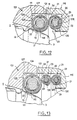
- . Figure 1 is a longitudinal sectional view of a butterfly valve equipped with a sealing device according to the invention;
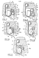
- . Figure 2 is an enlarged view of a detail of Figure 1, showing more particularly the sealing device;
- . Figure 3 is a graph for comparing the torque required to operate the valve with and without application of the invention;
- FIG. 4 is a graph showing the evolution of the operating torque of the shutter as a function of the temperature, in the case of the valve of FIGS. 1 and 2;
- . Figures 5 to 14 are views similar to Figure 2 and showing different embodiments of the sealing device according to the invention.
Dans l'exemple représenté à la figure 1, la vanne papillon comprend un corps 1 traversé par un conduit de section sensiblement circulaire 2 pour le passage du fluide. Dans ce conduit est monté un disque obturateur - ou papillon - 3 portant deux oreilles diamétralement opposées 4. L'une de ces oreilles 4 est liée en rotation à un arbre de commande 6 débouchant à l'extérieur du corps 1, tandis qu'un arbre 7 formant pivot, monté en rotation dans le , corps 1, est engagé dans l'autre oreille 4.In the example shown in Figure 1, the butterfly valve comprises a
L'obturateur 3 présente sur son pourtour une zone sphérique annulaire 8, déportée latéralement par rapport à l'axe commun X-X des arbres 6 et 7, et destinée, en position de fermeture de la vanne telle que représentée aux figures, à coopérer avec un dispositif d'étanchéité 9 pour obturer le passage 2.The
Comme le montre la figure 2, le dispositif d'étanchéité 9 comprend un siège principal 11 ayant une aile d'ancrage 12 fixée au corps 1, et une structure annulaire élastique d'obturation 13, sensiblement torique, qui fait saillie à l'intérieur du passage 2 pour coopérer avec la zone sphérique 8 de l'obturateur 3.As shown in Figure 2, the
L'aile d'ancrage 12 présente une partie plane, sensiblement radiale, adjacente à l'aile d'obturation 13, et insérée entre un épaulement 14 du corps 1 et une bague 16 vissée sur le corps 1. L'aile d'ancrage 12 présente, à l'opposé de la structure d'obturation 13, une partie roulée 17 logée dans un évidement annulaire 20 défini conjointement par l'épaulement 14 du corps 1 et la bague 16. La partie roulée 17r qui prend appui sur trois des quatre faces.de l'évidement 20, de section rectangulaire, assure l'étanchéité entre le corps 1 et la bague 16. A l'intérieur de la partie roulée 17 de l'aile d'ancrage 12 est installé un ressort hélicoïdal d'axe circulaire 15.The anchoring
La structure d'obturation 13 présente une enveloppe 18 roulée en direction opposée de l'axe X-X à partir de l'aile d'ancrage 12. L'aile d'ancrage 12 et l'enveloppe 18 forment une seule pièce réalisée en tôle de métal élastique tel que l'acier inoxydable. La section de l'enveloppe 18 correspond à un peu plus de trois quarts de cercle. A l'intérieur de l'enveloppe 18, est logée une enveloppe interne 19 réalisée elle aussi en tôle métallique élastique, et roulée de façon à être quasiment refermée sur elle-même, à l'exception d'une étroite fente annulaire 21. Un ressort hélicoïdal 22, d'axe circulaire est à son tour logé dans l'enveloppe interne 19.The
Conformément à l'invention, le dispositif d'étanchéité 9 comprend encore un siège auxiliaire 23 par l'intermédiaire duquel la structure d'obturation 13 du siège principal 11 prend appui contre la bague 16, à l'opposé de l'axe X-X. La structure d'obturation 13, sensiblement torique et le siège auxiliaire 23 sont tous deux montés dans un dégagement 24 ménagé dans la face interne de la bague 16. Ce dégagement annulaire 24 présente une face radiale - ou épaulement - 26 tournée vers le corps 1 et une face cylindrique 27 allant de la face 26 jusqu'au siège principal 11. Le siège auxiliaire 23 est intercalé entre la structure d'obturation torique 13 du siège 11 et la face radiale 26 du dégagement annulaire 24. Le siège auxiliaire 23, qui est du genre d'un joint torique, comprend une enveloppe extérieure 28 tout à fait analogue à l'enveloppe interne 19 du siège principal 11, excepté que le diamètre de son profil est voisin de celui de l'enveloppe externe 18. L'enveloppe 28 présente une surface extérieure convexe contre laquelle la structure d'obturation 13, et plus particulièrement l'enveloppe externe 18, prennent appui sur la bague 16 et le corps 1. La fente annulaire 21 de l'enveloppe 28 est de préférence située entre la génératrice circulaire de l'enveloppe 28 la plus proche de la surface cylindrique 27, et la génératrice circulaire de l'enveloppe 28 qui est en contact avec le siège principal 11.According to the invention, the
Un ressort hélicoïdal 29 d'axe circulaire, analogue au ressort 22 du siège 11, est logé à l'intérieur de l'enveloppe 28 du siège auxiliaire 23. Le diamètre des spires de ce ressort est voisin du diamètre du profil de l'enveloppe interne 19 du siège 11.A
Le siège qui vient d'être décrit fonctionne de la façon suivante :
- La partie plane de l'aile d'ancrage 12 assure la fixation du siège principal 11
au corps 1, tandis que la partie roulée 17 de l'aile 12 assure l'étanchéité entre le corps 1 et la bague 16, ainsi qu'entre le corps 1 et le siègeprincipal 11.
- The flat part of the
anchor wing 12 ensures the fixing of themain seat 11 to thebody 1, while the rolledpart 17 of thewing 12 ensures the seal between thebody 1 and thering 16, as well as between thebody 1 and themain seat 11.
En position de fermeture, la zone sphérique 8 de l'obturateur 3 est en contact avec l'enveloppe externe 18 de la structure d'obturation 13, selon une génératrice de cette dernière située entre l'aile d'ancrage 12 et la génératrice de contact avec le siège auxiliaire 23.In the closed position, the
Quand on ramène l'obturateur 3 en position de fermeture, l'enveloppe externe 18 du siège 11 tend à s'enrouler sur elle-même (flèche F1 de la figure 2). Ceci entraîne une légère augmentation du diamètre du tore que constitue la structure d'obturation 13 du siège 11. Par suite, le ressort 22 qu'il renferme s'étire et la fente 21 de l'enveloppe interne 19 tend à diminuer de largeur.When the
Sans que l'invention soit liée à cette explication, on suppose que les bons résultats que procure le siège qui vient d'être décrit, proviennent de ce que l'enveloppe externe 18, en s'enroulant sur elle-même selon la flèche F1, roule sans glisser sur l'enveloppe externe 28 du siège auxiliaire 23, provoquant chez ce dernier un mouvement tendant à faire diminuer la largeur de la fente 21, selon la flèche F2 de la figure 2. Ainsi, on constate que la déformation du siège principal 11, qui, au cours de l'ouverture de la fermeture de la vanne s'opère comme exposé dans le brevet français 2 331 725, est grandement facilitée.Without the invention being linked to this explanation, it is assumed that the good results obtained by the seat which has just been described, come from the fact that the
Par ailleurs, la présence du siège 23 permet à la vanne d'être exposée à de hautes pressions (par exemple 45 x 105 Pa) en évitant les déformations plastiques du siège principal 11, grâce, semble-t-il, à la déformation élastique du siège auxiliaire 23. Ainsi, une telle vanne peut ensuite être exposée à de basses pressions sans que l'étanchéité soit compromise en position de fermeture. Par ailleurs, il semble que l'élasticité du siège 23 compense les effets de la dilatation thermique de manière à conserver à la vanne son étanchéité et sa douceur de commande quelle que soit la température du fluide qui la traverse.Furthermore, the presence of the
Les bons résultats auxquels conduit l'invention sont visualisés aux graphiques des figures 3 et 4. A la figure 3, on a porté en abscisse le couple en m.N nécessaire pour faire pivoter l'obturateur 3 par action sur l'arbre de commande 6, en fin de fermeture ou en début d'ouverture, et en ordonnée, la pression en Pa x 105 du fluide dont la vanne contrôle le débit. La courbe C1 a été obtenue en effectuant des mesures sur une vanne du genre de celle de la figure 2, de 150 mm de diamètre du conduit 2. La courbe C2 concerne une vanne analogue mais dépourvue de siège 23, et dans laquelle l'enveloppe externe 18 du siège 11 est appuyée directement contre une surface annulaire concave formée dans la bague telle que 16, conformément au brevet français 2 331 725.The good results to which the invention leads are visualized in the graphs of FIGS. 3 and 4. In FIG. 3, the torque in mN necessary to rotate the
Il apparaît qu'à toutes les pressions, le dispositif d'étanchéité conforme à l'invention autorise un couple de manoeuvre inférieur à celui obtenu selon l'état de la technique, ce couple étant même réduit approximativement de moitié ou plus pour les pressions supérieures à 45 x 10 5 Pa.It appears that at all pressures, the sealing device according to the invention allows a lower operating torque than that obtained according to the state of the art, this torque even being reduced approximately by half or more for higher pressures. at 45 x 10 5 Pa.
A la figure 4, on a porté en abscisse le couple en m.N de manoeuvre de l'obturateur à partir de l'arbre de commande 6 en fin de fermeture ou en début d'ouverture, et en ordonnée, la température en degrés C du fluide dont la vanne contrôle le débit.In FIG. 4, we have plotted on the abscissa the torque in mN of actuation of the shutter from the
La courbe représentée a été obtenue en effectuant des mesures sur une vanne du genre de celle de la figure 1, dans laquelle le passage 2 avait 150 mm de diamètre. Cette courbe montre que le couple de manoeuvre de l'obturateur est sensiblement constant jusqu'à plus de 350°C.The curve shown was obtained by carrying out measurements on a valve of the kind of that of FIG. 1, in which the
Le mode de réalisation représenté à la figure 5 est bien adapté pour les vannes de petit diamètre ou les vannes dont le prix de revient doit rester modéré.The embodiment shown in Figure 5 is well suited for small diameter valves or valves whose cost must remain moderate.
Ce dispositif d'étanchéité ne sera décrit qu'en ce qui concerne ses différences par rapport à celui de la figure 2. Il comprend un siège principal 31 dont l'aile d'ancrage 12 est analogue à celle de la figure 2, et la structure d'obturation 12 est analogue à l'enveloppe externe 18 du siège 2. Par ailleurs, le dispositif d'étanchéité 31 comprend un siège auxiliaire 33 constitué par une nervure annulaire à section en secteur de cercle, ménagée sur la face radiale 36 de l'évidement annulaire 34 que présente la paroi interne de la bague 37 qui, par ailleurs, joue le même rôle que la bague 16 de la figure 2.This sealing device will only be described with regard to its differences from that of FIG. 2. It comprises a
Le mode de réalisation représenté à la figure 6, est au contraire plus particulièrement destiné à des vannes de diamètre relativement importants, ou à des vannes de haute qualité dont le prix de revient peut être plus élevé. Le siège principal 11 est analogue à celui de la figure 2, excepté qu'une enveloppe interne 50 est insérée entre la partie roulée 17 de l'aile d'ancrage 12 et le ressort 15. Le dispositif d'étanchéité comprend deux sièges auxiliaires 23 montés en série antre la structure d'obturation 13 du siège principal 11 et la face radiale du dégagement annulaire 44 ménagé dans la bague 47, qui joue par ailleurs un rôle analogue à celui de la bague 16 de la figure 2. Les sièges 23 sont analogues au siège 23 de la figure 2, tandis que la dimension axiale du dégagement 44 est augmentée en conséquence par rapport à celle du dégagement 24 de la figure 2. De préférence, la fente 21 de l'enveloppe externe du siège 23 adjacent au siège principal 11 occupe la même position que la fente 21 de la figure 2, tandis que la fente 21 de l'autre siège 23 est située entre les génératrices circulaires de contact avec respectivement le premier siège 23 et la face 46, du côté de l'axe du conduit 2. Dans l'exemple représenté, la fente 21 de ce siège 23 est en position à peu près diamétralement opposée à celle du premier siège 23.The embodiment shown in Figure 6, on the contrary is more particularly intended for valves of relatively large diameter, or to high quality valves whose cost price may be higher. The
Dans ce dispositif d'étanchéité, l'enroulement selon la flèche F2 du siège 23 adjacent au siège principal 11, entraîne l'enroulement selon la flèche F3 de l'autre siège 23, et la fermeture de la fente annulaire 21 de ce dernier.In this sealing device, the winding along arrow F2 of the
Aux figures 7 à 11, le siège principal 31 est analogue à celui de la figure 5.In FIGS. 7 to 11, the
Comme le montre la figure 7, le siège principal 31 peut prendre appui sur le corps 1 par l'intermédiaire de deux sièges 53a, 53b, montés en parallèle entre l'enveloppe 18 et la bague 57 vissée au corps 1. Les sièges 53a, 53b sont analogues au siège 23, sauf que le diamètre de leur section est plus réduit et qu'ils ne renferment pas de ressorts hélicoïdaux.As shown in FIG. 7, the
Le siège 53a présente un diamètre de tore identique à celui de l'enveloppe 18 du siège principal 31,'tandis que l'autre, 53b, est sensiblement plus grand, de sorte qu'il est également légèrement plus proche de l'axe X-X. L'évidement 54 de la bague 57 présente deux faces radiales 56a, 56b, toutes deux dirigées vers l'axe X-X, et séparées par un rebord 56f. Ainsi, les sièges 53a, 53b, qui sont en appui l'un sur l'autre, sont chacun intercalés entre l'enveloppe 18 et l'une des faces 56a ou 56b respectivement, de l'évidement 54.The
La fente 21 du siège 53a est située entre la génératrice circulaire de contact avec l'enveloppe 18 et la génératrice circulaire de contact avec le siège 53b, tandis que la fente 21 du siège 53b est située entre la génératrice de contact avec l'enveloppe 18 et la génératrice la plus proche de la surface cylindrique 58 de l'évidement 54.The
Quand on amène l'obturateur 3 en position de fermeture en appui contre l'enveloppe 18, celle-ci s'enroule provoquant l'enroulement simultané des sièges 53a et 53b dont les fentes annulaires 21 ont tendance à se refermer.When the
Dans cette réalisation, on parvient à réduire très fortement les frottements qui pourraient s'opposer à l'enroulement de l'enveloppe 18, tout en assurant une très bonne stabilité au siège, ce qui conforte sa résistance à la pression.In this embodiment, it is possible to very greatly reduce the friction which could oppose the winding of the
Le mode de réalisation de la figure 8 est analogue à celui de la figure 7, excepté que les sièges 53a et 53b ne sont pas en contact l'un avec l'autre. En effet, les diamètres moyens des tores qu'ils constituent, présentent entre eux une différence plus importante que dans la figure 7. Par ailleurs, les surfaces radiales 56a et 56b de l'évidement 54 sont séparées par une nervure 56e assurant le centrage du siège 53a par rapport à l'axe du conduit 2. Dans cet exemple, la fente 21 du siège 53a est située entre la génératrice annulaire de contact avec l'enveloppe 18 et la génératrice la plus proche de la nervure 56e.The embodiment of Figure 8 is similar to that of Figure 7, except that the
Le mode de réalisation de la figure 9 est plus particulièrement destiné à des vannes de grand diamètre de passage, par exemple 1 m ou plus. Cet exemple est analogue à celui de la figure 8, sauf que ce sont quatre sièges toriques 53a, 53b, 53c, 53d qui sont interposés entre l'enveloppe 18 et la bague 57 qui est vissée au corps 1.The embodiment of FIG. 9 is more particularly intended for valves with a large passage diameter, for example 1 m or more. This example is similar to that of FIG. 8, except that there are four O-
L'appui des sièges 53a à 53d sur la bague 57, a lieu sur quatre surfaces annulaires radiales 56a,56b,56c,56d de l'évidement 54, dirigées vers l'axe X-X. Les surfaces 56a et 56b sont alignées et-séparées par une nervure 56e qui assure le centrage du siège 53a par rapport à l'axe du conduit 2. Les surfaces 56b, 56c et 56d, qui sont décalées en gradins, sont séparées par des rebords 56f et 56g qui assurent respectivement le centrage des sièges 53b et 53c. Le siège 53d qui a le plus grand diamètre, est centré par le fond 58 de l'évidement 54. Les sièges 53a à 53d ont leur fente 21 située entre la génératrice circulaire de contact avec l'enveloppe 18 et, selon les cas, la nervure 56e, les rebords 56f, 56Q ou la surface cylindrique 58.The support of the
Ainsi, .quand l'enveloppe 18 s'enroule sous l'effet de la fermeture de l'obturateur 3, chaque siège 53a, 53b ou 53d se referme légèrement.Thus, when the
Dans l'exemple de la figure 10, l'enveloppe 18 du siège 31 est supportée par un seul siège 53 analogue au siège 53a ou 53b de la figure 7. Ce siège 53 est comme dans les figures 7 à 9 précédentes, en appui contre une surface radiale 56 du dégagement 54.In the example of Figure 10, the
En outre, le siège 53 est monté de telle manière que, en coupe comme représenté à la figure 10, son point de contact A avec l'enveloppe 18, soit situé sur la perpendiculaire L aux surfaces de la zone sphérique 8 et de l'enveloppe 18, issue du point B de contact entre ces deux surfaces.In addition, the
L'exemple de la figure 11 est voisin de celui de la figure 10, excepté que le dispositif d'étanchéité comprend ici deux sièges auxiliaires 53a, 53b répartis de part et d'autre de la ligne L. Chaque siège 53a, 53b'est en appui contre la bague 57 qui présente à cet effet deux surfaces radiales planes 56a, 56b.The example of FIG. 11 is close to that of FIG. 10, except that the sealing device here comprises two
Dans l'exemple de la figure 12, le siège principal 111 comprend uniquement une structure d'obturation analogue à celle de la figure 2 sauf que l'enveloppe externe 118 est sensiblement torique et entièrement refermée sur elle-même à l'exception d'une fente annulaire 121. Le siège 111 est monté dans un dégagement annulaire 124 que présente le corps 101 en prolongement du dégagement 24 de la bague 116. L'enveloppe externe 118 est appuyée de façon étanche contre la paroi radiale plane 125 du dégagement 124, qui est située sensiblement à l'opposé du siège auxiliaire 23. Par contre, un espace peut subsister entre l'enveloppe 118 et la paroi cylindrique 127 du dégagement 124.In the example of FIG. 12, the
Le siège auxiliaire 23 est analogue à celui de la figure 2, excepté que son profil peut être de diamètre légèrement réduit et qu'une enveloppe interne 128 est interposée entre l'enveloppe externe 28 et le ressort 29.The
Un rebord 126, qui sépare du conduit 2 la face plane 26 du dégagement 24 peut renforcer le positionnement du siège auxiliaire 23.A
La fente 21 est disposée comme dans la réalisation de la figure 2, et la fente 121 du siège 111 est disposée de façon sensiblement symétrique à la fente 21 par rapport au plan de contact entre les sièges 111 et 23.The
L'enroulement de l'enveloppe externe 118, qui provoque une variation de la largeur de la fente 121, entraîne l'enroulement de l'enveloppe externe 28 et la diminution de largeur de la fente 21. Le siège principal 111, qui n'est en appui que sur la face plane 125 et le siège auxiliaire 23, se centre de lui-même sur l'obturateur 3 quand celui-ci arrive en position de fermeture, ce qui réduit les risques de fuite localisée à une certaine partie de la périphérie de l'obturateur.The winding of the
Dans cette version, l'invention permet également d'adoucir le couple de manoeuvre et d'augmenter les performances d'étanchéité de la vanne. Cette étanchéité s'effectue, avec l'obturateur 3, selon la ligne P de contact entre l'obturateur 3 et l'enveloppe 188, et avec le corps 101, selon la ligne Q de contact entre l'enveloppe 118 et la face radiale 125 du dégagement 124, ainsi que selon la ligne R de contact élastique entre les enveloppes 118 et 28, et selon la ligne S de contact entre l'enveloppe 28 et la face 29 du dégagement 24.In this version, the invention also makes it possible to soften the operating torque and to increase the sealing performance of the valve. This sealing takes place, with the
Un joint torique additionnel, non représenté, d'un genre connu, peut en outre être interposé entre le corps 101 et la bague 116.An additional O-ring, not shown, of a known type, may also be interposed between the
La version de la figure 13 est analogue à celle de la figure 12, excepté que le dégagement annulaire 24 de la bague 116 renferme deux sièges auxiliaires 123 disposés comme dans la réalisation de la figure 6.The version of FIG. 13 is similar to that of FIG. 12, except that the
La présente version est plus particulièrement destinée à des vannes de grand diamètre et/ou de haute qualité.This version is more particularly intended for large diameter and / or high quality valves.
La réalisation de la figure 14 ne sera décrite qu'en ce qui concerne ses différences par rapport à la figure 12.The embodiment of FIG. 14 will only be described with regard to its differences from FIG. 12.
Le siège auxiliaire 23 est de plus grand diamètre d'anneau et de plus petit diamètre de profil que celui de la figure 12, et les surfaces cylindriques 27 et 127 des dégagements 24 et 124 sont de plus grand diamètre que celles de la figure 12. Ainsi, le siège principal 111 est en appui oblique contre la paroi radiale 26 du dégagement 24.The
Un second siège auxiliaire 123 est interposé entre le siège principal 111 et la paroi radiale 125 du dégagement 124, de façon symétrique au siège 23 par rapport au plan du siège 111.A second
Le siège 123 est analogue au siège 23, excepté que la fente 21 concerne la partie de l'enveloppe externe 28 tournée vers le conduit 2 et s'étendant entre la ligne T de contact avec le siège principal 111 et la ligne U de contact avec la face 125.
En position de fermeture de la vanne, l'étanchéité entre le siège principal 111 et le corps 101 s'effectue selon les lignes T et U ainsi que selon les lignes homologues V et W concernant le siège 23. L'étanchéité entre le siège 111 et l'obturateur 3 résulte de la ligne de contact S entre ces deux pièces.In the valve closed position, the seal between the
Au cours dr la manoeuvre de l'obturateur 3, ce mode de réalisation du dispositif d'étanchéité permet également au siège principal 111 de s'enrouler et de se dérouler avec les frottements réduits.During the operation of the
On voit donc que l'invention se prête à de nombreuses applications, et le choix entre un mode de réalisation ou l'autre pourra s'effectuer en fonction du compromis recherché entre la pression que peut supporter la vanne et la douceur de commande souhaitée sur l'arbre de commande 6. D'autres facteurs peuvent également être considérés, tels que prix de revient, ou diamètre d'écoulement du fluide dans la vanne.It can therefore be seen that the invention lends itself to numerous applications, and the choice between one embodiment or the other may be made as a function of the compromise sought between the pressure which the valve can withstand and the desired softness of control over the
Le travail à l'enroulement de la structure d'obturation favorisé par le .siège auxiliaire conforme à l'invention, permet de limiter la pression de contact notamment entre le siège principal et l'obturateur. Les déformations du siège principal et du ou des sièges auxiliaires restent élastiques, ce qui confère à la vanne sa bonne résistance aux variations de température et de pression.The work in winding the closure structure favored by the auxiliary seat according to the invention makes it possible to limit the contact pressure in particular between the main seat and the shutter. The deformations of the main seat and of the auxiliary seat (s) remain elastic, which gives the valve its good resistance to variations in temperature and pressure.
Les avantages auxquels conduit l'invention sont surprenants car l'homme du métier est induit à penser que la pression de contact élevée qui prend naissance entre deux surfaces convexes telles que celles de l'aile d'obturation et du siège auxiliaire conformes à l'invention est de nature à rendre très difficile l'enroulement du siège principal quand l'obturateur atteint ou quitte la position de fermeture, donc à augmenter le couple nécessaire pour manoeuvrer la vanne.The advantages to which the invention leads are surprising because the person skilled in the art is led to think that the high contact pressure which arises between two convex surfaces such as those of the obturation wing and of the auxiliary seat in accordance with invention is likely to make winding the seat very difficult main when the shutter reaches or leaves the closed position, therefore increasing the torque necessary to operate the valve.
Bien entendu, l'invention n'est pas limitée aux exemples qui viennent d'être décrits et de nombreux aménagements ou perfectionnements peuvent être apportés à ces exemples sans sortir du cadre de l'invention.Of course, the invention is not limited to the examples which have just been described and numerous modifications or improvements can be made to these examples without departing from the scope of the invention.
En particulier, on peut munir d'un ressort hélicoïdal et éventuellement d'une enveloppe interne les ailes d'ancrage, structures d'obturation ou joints auxiliaires dans les exemples où ceux-ci ne comprennent qu'une simple enveloppe en tôle roulée.In particular, it is possible to provide a helical spring and possibly an internal envelope for the anchoring wings, obturation structures or auxiliary seals in the examples where these comprise only a simple envelope made of rolled sheet.
D'autre part, le dispositif d'étanchéité conforme à l'invention est applicable à tout type de vanne pouvant recevoir un siège principal du genre revendiqué.On the other hand, the sealing device according to the invention is applicable to any type of valve which can receive a main seat of the claimed type.
Claims (17)
Applications Claiming Priority (2)
| Application Number | Priority Date | Filing Date | Title |
|---|---|---|---|
| FR8026371A FR2496217A1 (en) | 1980-12-12 | 1980-12-12 | VALVE SEALING DEVICE |
| FR8026371 | 1980-12-12 |
Publications (2)
| Publication Number | Publication Date |
|---|---|
| EP0054473A1 true EP0054473A1 (en) | 1982-06-23 |
| EP0054473B1 EP0054473B1 (en) | 1985-06-26 |
Family
ID=9248977
Family Applications (1)
| Application Number | Title | Priority Date | Filing Date |
|---|---|---|---|
| EP81401933A Expired EP0054473B1 (en) | 1980-12-12 | 1981-12-04 | Valve seal |
Country Status (8)
| Country | Link |
|---|---|
| US (1) | US4477057A (en) |
| EP (1) | EP0054473B1 (en) |
| JP (1) | JPS608381B2 (en) |
| CA (1) | CA1160614A (en) |
| DE (1) | DE3171148D1 (en) |
| FR (1) | FR2496217A1 (en) |
| MX (1) | MX154577A (en) |
| ZA (1) | ZA818524B (en) |
Cited By (3)
| Publication number | Priority date | Publication date | Assignee | Title |
|---|---|---|---|---|
| FR2559232A1 (en) * | 1984-02-03 | 1985-08-09 | Rollot Andre | Valve with a spherical butterfly |
| FR2581728A1 (en) * | 1985-05-10 | 1986-11-14 | Munzing Sa | ANNULAR SEALING DEVICE, IN PARTICULAR FOR VALVES AND VALVES |
| WO2008036576A1 (en) * | 2006-09-21 | 2008-03-27 | Fisher Controls International Llc | Metal seal with flexible insert |
Families Citing this family (36)
| Publication number | Priority date | Publication date | Assignee | Title |
|---|---|---|---|---|
| JPS59141262U (en) * | 1983-03-11 | 1984-09-20 | 株式会社巴技術研究所 | metal sheet ring |
| JPS59141263U (en) * | 1983-03-11 | 1984-09-20 | 株式会社巴技術研究所 | seat ring |
| JPS63130888A (en) * | 1986-11-20 | 1988-06-03 | 日本建鐵株式会社 | Method for mounting doormat |
| JPS646564A (en) * | 1987-06-29 | 1989-01-11 | Akira Oshima | Sealing device for butterfly valve |
| JPH01188772A (en) * | 1988-01-21 | 1989-07-28 | Akira Oshima | Seal device for both positive/back pressure of butterfly valve |
| US4848729A (en) * | 1988-02-01 | 1989-07-18 | Dresser Industries, Inc. | Valve seal |
| FR2636115B1 (en) * | 1988-09-08 | 1990-10-19 | Commissariat Energie Atomique | HIGHLY SPECIFIC PRESSURE METAL GASKET |
| FR2686136B1 (en) * | 1992-01-15 | 1995-06-30 | Alsthom Velan | METALLIC JOINT VALVE, ESPECIALLY BUTTERFLY VALVE. |
| US5433456A (en) * | 1992-12-18 | 1995-07-18 | The Advanced Products Company | Spring energized convoluted surface seal |
| DE4300191A1 (en) * | 1993-01-07 | 1994-07-14 | Klein Schanzlin & Becker Ag | Metal seal |
| FR2721086B1 (en) * | 1994-06-14 | 1996-07-12 | Commissariat Energie Atomique | Cable gland with elastic mounting of seals. |
| DE4424122C2 (en) * | 1994-07-08 | 1999-06-10 | Xomox Int Gmbh | Butterfly valve |
| JP2000508742A (en) * | 1996-04-18 | 2000-07-11 | ゼネラル シグナル コーポレイション | Two-way valve seal mechanism |
| US6120037A (en) * | 1997-05-20 | 2000-09-19 | Schmertz; John C. | Amplified pressure force seal |
| DE10251385A1 (en) * | 2002-11-01 | 2004-05-13 | Siemens Ag | Valve |
| US6983940B2 (en) * | 2003-07-29 | 2006-01-10 | American Seal And Engineering Company, Inc. | Metallic seal |
| KR100729839B1 (en) | 2006-04-19 | 2007-06-21 | 피케이밸브 주식회사 | Live load supporting type butterfly valve |
| DE102007062681A1 (en) * | 2007-12-24 | 2009-06-25 | Man Turbo Ag | Sealing segment and sealing segment arrangement |
| US8511972B2 (en) * | 2009-12-16 | 2013-08-20 | Siemens Energy, Inc. | Seal member for use in a seal system between a transition duct exit section and a turbine inlet in a gas turbine engine |
| CN102853093A (en) * | 2011-06-30 | 2013-01-02 | 江苏神通阀门股份有限公司 | Double-acting type isolating valve |
| US9611712B2 (en) * | 2012-02-09 | 2017-04-04 | Onesubsea Ip Uk Limited | Lip seal |
| WO2017011673A2 (en) * | 2015-07-14 | 2017-01-19 | Hartman Thomas A | Spring ring valve seat and butterfly valve with spring ring valve seat |
| CN106151543A (en) * | 2016-07-22 | 2016-11-23 | 苏州纽威阀门股份有限公司 | A kind of hard seal butterfly valve |
| CA3031821C (en) * | 2016-07-28 | 2020-11-03 | Flowserve Management Company | Shutoff seal for high temperature pressure balance valve and related methods |
| US10309562B2 (en) * | 2017-07-18 | 2019-06-04 | Freudenberg Oil & Gas, Llc | Metal to metal wedge ring seal |
| JP6907807B2 (en) * | 2017-08-22 | 2021-07-21 | 株式会社デンソー | Composite seal ring |
| CN107842628B (en) * | 2017-11-28 | 2023-09-01 | 西铁阀门科技有限公司 | Two-way pressure universal automatic compensation valve seat pressure plate type valve |
| CN108019523B (en) * | 2017-12-01 | 2024-01-30 | 中国船舶重工集团公司第七一九研究所 | Integrated cup-shaped pipe joint |
| FR3079903B1 (en) * | 2018-04-04 | 2022-12-23 | Commissariat Energie Atomique | METAL SEAL ASSEMBLY FOR SEALING BETWEEN A ROTATING SHAFT AND A FIXED FRAME |
| CN108533760A (en) * | 2018-05-29 | 2018-09-14 | 芜湖三花自控元器件有限公司 | A kind of novel cutoff valve sealing structure |
| CN109210224B (en) * | 2018-10-10 | 2024-06-21 | 中冶南方工程技术有限公司 | Bidirectional sealing sluice valve |
| CN109185469B (en) * | 2018-10-10 | 2024-06-21 | 中冶南方工程技术有限公司 | Self-locking bidirectional sealing gate valve |
| CN110608290A (en) * | 2019-10-23 | 2019-12-24 | 江苏神通阀门股份有限公司 | Three-eccentric metal seal butterfly valve structure with online replaceable seal pair |
| US11467056B2 (en) | 2019-11-01 | 2022-10-11 | Saudi Arabian Oil Company | Sensing leak in a multi-seal sealing assembly with sensors |
| CN114776827B (en) * | 2022-04-12 | 2024-03-26 | 浙江贝尔控制阀门有限公司 | Improved eccentric rotary valve |
| CN116557558B (en) * | 2023-05-16 | 2023-09-29 | 建湖县鸿达阀门管件有限公司 | 175MPa sand control formula flatbed valve |
Citations (5)
| Publication number | Priority date | Publication date | Assignee | Title |
|---|---|---|---|---|
| FR2056552A5 (en) * | 1969-08-06 | 1971-05-14 | Hills Mccanna Co | |
| FR2253959A1 (en) * | 1973-12-05 | 1975-07-04 | Valve Syst Int Inc | |
| FR2300944A1 (en) * | 1975-02-11 | 1976-09-10 | Fisher Controls Co | BI-DIRECTIONAL SEAL AND ITS APPLICATION TO A VALVE |
| FR2326637A1 (en) * | 1975-10-02 | 1977-04-29 | Fisher Controls Co | METAL SEAL, BIDIRECTIONAL, FOR HIGH TEMPERATURES |
| GB2001738A (en) * | 1977-07-26 | 1979-02-07 | Amri | Sealing ring |
Family Cites Families (3)
| Publication number | Priority date | Publication date | Assignee | Title |
|---|---|---|---|---|
| US3250510A (en) * | 1964-02-18 | 1966-05-10 | Crane Co | Self-adjustable seats for butterfly valves or the like |
| FR2331725A1 (en) * | 1975-11-14 | 1977-06-10 | Realmeca | Annular seat for butterfly and ball valves - has stainless steel envelope and asbestos filling to resist high temperatures and pressures |
| US4247079A (en) * | 1979-09-06 | 1981-01-27 | Societe Meusienne De Realisations Mecaniques "Realmeca" | Annular valve seating |
-
1980
- 1980-12-12 FR FR8026371A patent/FR2496217A1/en active Granted
-
1981
- 1981-12-04 EP EP81401933A patent/EP0054473B1/en not_active Expired
- 1981-12-04 DE DE8181401933T patent/DE3171148D1/en not_active Expired
- 1981-12-08 US US06/328,645 patent/US4477057A/en not_active Expired - Lifetime
- 1981-12-08 ZA ZA818524A patent/ZA818524B/en unknown
- 1981-12-10 CA CA000391963A patent/CA1160614A/en not_active Expired
- 1981-12-11 MX MX190587A patent/MX154577A/en unknown
- 1981-12-11 JP JP56198779A patent/JPS608381B2/en not_active Expired
Patent Citations (5)
| Publication number | Priority date | Publication date | Assignee | Title |
|---|---|---|---|---|
| FR2056552A5 (en) * | 1969-08-06 | 1971-05-14 | Hills Mccanna Co | |
| FR2253959A1 (en) * | 1973-12-05 | 1975-07-04 | Valve Syst Int Inc | |
| FR2300944A1 (en) * | 1975-02-11 | 1976-09-10 | Fisher Controls Co | BI-DIRECTIONAL SEAL AND ITS APPLICATION TO A VALVE |
| FR2326637A1 (en) * | 1975-10-02 | 1977-04-29 | Fisher Controls Co | METAL SEAL, BIDIRECTIONAL, FOR HIGH TEMPERATURES |
| GB2001738A (en) * | 1977-07-26 | 1979-02-07 | Amri | Sealing ring |
Cited By (7)
| Publication number | Priority date | Publication date | Assignee | Title |
|---|---|---|---|---|
| FR2559232A1 (en) * | 1984-02-03 | 1985-08-09 | Rollot Andre | Valve with a spherical butterfly |
| FR2581728A1 (en) * | 1985-05-10 | 1986-11-14 | Munzing Sa | ANNULAR SEALING DEVICE, IN PARTICULAR FOR VALVES AND VALVES |
| EP0202156A1 (en) * | 1985-05-10 | 1986-11-20 | Munzing S.A. | Anular sealing device, especially for valves or taps |
| WO2008036576A1 (en) * | 2006-09-21 | 2008-03-27 | Fisher Controls International Llc | Metal seal with flexible insert |
| US7963503B2 (en) | 2006-09-21 | 2011-06-21 | Fisher Controls International Llc | Metal seal with flexible insert |
| EP2581633A3 (en) * | 2006-09-21 | 2014-05-07 | Fisher Controls International Llc | Metal seal with flexible insert |
| EP2581634A3 (en) * | 2006-09-21 | 2014-05-07 | Fisher Controls International Llc | Metal seal with flexible insert |
Also Published As
| Publication number | Publication date |
|---|---|
| CA1160614A (en) | 1984-01-17 |
| EP0054473B1 (en) | 1985-06-26 |
| MX154577A (en) | 1987-10-02 |
| FR2496217A1 (en) | 1982-06-18 |
| DE3171148D1 (en) | 1985-08-01 |
| US4477057A (en) | 1984-10-16 |
| ZA818524B (en) | 1982-10-27 |
| JPS57124166A (en) | 1982-08-02 |
| FR2496217B1 (en) | 1983-03-04 |
| JPS608381B2 (en) | 1985-03-02 |
Similar Documents
| Publication | Publication Date | Title |
|---|---|---|
| EP0054473B1 (en) | Valve seal | |
| EP0231673B1 (en) | Composite sealing arrangement | |
| EP2895773B1 (en) | Gasket, in particular for a pressurised liquid | |
| EP1331403A1 (en) | Stator blade control apparatus | |
| CH626144A5 (en) | ||
| EP0166641A1 (en) | Sealing device assuring the opstream/downstream fluid tightness of a closure member | |
| EP0631072A1 (en) | Seal for rotating shaft | |
| FR2754583A1 (en) | VALVE, ESPECIALLY FOR TUBING OF AN EXHAUST LINE | |
| FR2753750A1 (en) | ALTERNATIVE PISTON MACHINE | |
| FR2605706A1 (en) | PRESSURE REGULATION VALVE | |
| FR2573161A1 (en) | SPEED DRIVE PULLEY WITH SEAL SEAL AROUND HUB. | |
| EP0884505A1 (en) | Device with pivotable lever for transmission of movement and valve incorporating such a device | |
| EP2986877B1 (en) | Valve, in particular an engine control valve, equipped with a metering gate and a diverter gate | |
| FR2619430A1 (en) | COUPLING AND BRAKING DEVICE THAT CAN BE SWITCHED BY A COMPRESSIBLE FLUID, ESPECIALLY PNEUMATIC | |
| FR2897120A1 (en) | Pivot for variable-angle turbine compressor blade has one or more flat surfaces to co-operate with matching surfaces in angle adjustment lever | |
| FR2727730A1 (en) | FRICTION CLUTCH WITH CLUTCH DISC COMPRISING A TORSION SHOCK ABSORBER | |
| FR2782547A1 (en) | EXPANSION VALVE | |
| CA2418233C (en) | Blade control device with variable blade angle and tight attachment | |
| FR2581728A1 (en) | ANNULAR SEALING DEVICE, IN PARTICULAR FOR VALVES AND VALVES | |
| EP0179078B1 (en) | Hydraulic turbine having a partially dry-running rotor and a injector | |
| FR2683289A1 (en) | Seal for a butterfly valve and butterfly valve provided with such a seal | |
| FR3114368A1 (en) | Metal sealing system for triple offset butterfly valve | |
| EP2013501B1 (en) | Clutch bearing | |
| EP0592303B1 (en) | Electric motor bearing, retaining cup for such a bearing and electric motor equipped with such a bearing | |
| FR2468818A1 (en) | VALVE MANEUVER ASSEMBLY |
Legal Events
| Date | Code | Title | Description |
|---|---|---|---|
| PUAI | Public reference made under article 153(3) epc to a published international application that has entered the european phase |
Free format text: ORIGINAL CODE: 0009012 |
|
| 17P | Request for examination filed |
Effective date: 19811209 |
|
| AK | Designated contracting states |
Designated state(s): BE CH DE GB IT LI NL |
|
| ITCL | It: translation for ep claims filed |
Representative=s name: BARZANO' E ZANARDO ROMA S.P.A. |
|
| TCNL | Nl: translation of patent claims filed | ||
| DET | De: translation of patent claims | ||
| RAP1 | Party data changed (applicant data changed or rights of an application transferred) |
Owner name: GACHOT S.A. |
|
| ITF | It: translation for a ep patent filed | ||
| GRAA | (expected) grant |
Free format text: ORIGINAL CODE: 0009210 |
|
| AK | Designated contracting states |
Designated state(s): BE CH DE GB IT LI NL |
|
| REF | Corresponds to: |
Ref document number: 3171148 Country of ref document: DE Date of ref document: 19850801 |
|
| PLBE | No opposition filed within time limit |
Free format text: ORIGINAL CODE: 0009261 |
|
| STAA | Information on the status of an ep patent application or granted ep patent |
Free format text: STATUS: NO OPPOSITION FILED WITHIN TIME LIMIT |
|
| 26N | No opposition filed | ||
| PGFP | Annual fee paid to national office [announced via postgrant information from national office to epo] |
Ref country code: NL Payment date: 19861231 Year of fee payment: 6 |
|
| PG25 | Lapsed in a contracting state [announced via postgrant information from national office to epo] |
Ref country code: NL Effective date: 19880701 |
|
| NLV4 | Nl: lapsed or anulled due to non-payment of the annual fee | ||
| ITTA | It: last paid annual fee | ||
| REG | Reference to a national code |
Ref country code: CH Ref legal event code: NV Representative=s name: BOVARD AG PATENTANWAELTE |
|
| PGFP | Annual fee paid to national office [announced via postgrant information from national office to epo] |
Ref country code: GB Payment date: 19981120 Year of fee payment: 18 |
|
| PGFP | Annual fee paid to national office [announced via postgrant information from national office to epo] |
Ref country code: CH Payment date: 19981214 Year of fee payment: 18 |
|
| PGFP | Annual fee paid to national office [announced via postgrant information from national office to epo] |
Ref country code: BE Payment date: 19990205 Year of fee payment: 18 |
|
| PGFP | Annual fee paid to national office [announced via postgrant information from national office to epo] |
Ref country code: DE Payment date: 19990225 Year of fee payment: 18 |
|
| PG25 | Lapsed in a contracting state [announced via postgrant information from national office to epo] |
Ref country code: GB Free format text: LAPSE BECAUSE OF NON-PAYMENT OF DUE FEES Effective date: 19991204 |
|
| PG25 | Lapsed in a contracting state [announced via postgrant information from national office to epo] |
Ref country code: LI Free format text: LAPSE BECAUSE OF NON-PAYMENT OF DUE FEES Effective date: 19991231 Ref country code: CH Free format text: LAPSE BECAUSE OF NON-PAYMENT OF DUE FEES Effective date: 19991231 Ref country code: BE Free format text: LAPSE BECAUSE OF NON-PAYMENT OF DUE FEES Effective date: 19991231 |
|
| BERE | Be: lapsed |
Owner name: GACHOT S.A. Effective date: 19991231 |
|
| GBPC | Gb: european patent ceased through non-payment of renewal fee |
Effective date: 19991204 |
|
| PG25 | Lapsed in a contracting state [announced via postgrant information from national office to epo] |
Ref country code: DE Free format text: LAPSE BECAUSE OF NON-PAYMENT OF DUE FEES Effective date: 20001003 |