EP0054210A1 - Process for coating metallic tubes - Google Patents
Process for coating metallic tubes Download PDFInfo
- Publication number
- EP0054210A1 EP0054210A1 EP81109982A EP81109982A EP0054210A1 EP 0054210 A1 EP0054210 A1 EP 0054210A1 EP 81109982 A EP81109982 A EP 81109982A EP 81109982 A EP81109982 A EP 81109982A EP 0054210 A1 EP0054210 A1 EP 0054210A1
- Authority
- EP
- European Patent Office
- Prior art keywords
- layer
- powder
- hardener
- epoxy
- epoxy resin
- Prior art date
- Legal status (The legal status is an assumption and is not a legal conclusion. Google has not performed a legal analysis and makes no representation as to the accuracy of the status listed.)
- Withdrawn
Links
Images

Classifications
-
- B—PERFORMING OPERATIONS; TRANSPORTING
- B05—SPRAYING OR ATOMISING IN GENERAL; APPLYING FLUENT MATERIALS TO SURFACES, IN GENERAL
- B05D—PROCESSES FOR APPLYING FLUENT MATERIALS TO SURFACES, IN GENERAL
- B05D7/00—Processes, other than flocking, specially adapted for applying liquids or other fluent materials to particular surfaces or for applying particular liquids or other fluent materials
- B05D7/50—Multilayers
- B05D7/52—Two layers
- B05D7/53—Base coat plus clear coat type
-
- B—PERFORMING OPERATIONS; TRANSPORTING
- B05—SPRAYING OR ATOMISING IN GENERAL; APPLYING FLUENT MATERIALS TO SURFACES, IN GENERAL
- B05D—PROCESSES FOR APPLYING FLUENT MATERIALS TO SURFACES, IN GENERAL
- B05D7/00—Processes, other than flocking, specially adapted for applying liquids or other fluent materials to particular surfaces or for applying particular liquids or other fluent materials
- B05D7/14—Processes, other than flocking, specially adapted for applying liquids or other fluent materials to particular surfaces or for applying particular liquids or other fluent materials to metal, e.g. car bodies
- B05D7/148—Processes, other than flocking, specially adapted for applying liquids or other fluent materials to particular surfaces or for applying particular liquids or other fluent materials to metal, e.g. car bodies using epoxy-polyolefin systems in mono- or multilayers
-
- B—PERFORMING OPERATIONS; TRANSPORTING
- B05—SPRAYING OR ATOMISING IN GENERAL; APPLYING FLUENT MATERIALS TO SURFACES, IN GENERAL
- B05D—PROCESSES FOR APPLYING FLUENT MATERIALS TO SURFACES, IN GENERAL
- B05D7/00—Processes, other than flocking, specially adapted for applying liquids or other fluent materials to particular surfaces or for applying particular liquids or other fluent materials
- B05D7/50—Multilayers
- B05D7/56—Three layers or more
- B05D7/57—Three layers or more the last layer being a clear coat
Definitions
- the invention relates to a method for the outer coating of a metal tube with at least two organic composite layers and subsequent polyethylene sheathing by applying at least one layer which promotes adhesion and corrosion protection to the metallic substrate and further application of at least one layer which promotes polyethylene.
- the coating of metal pipes with polyethylene is done in practice so that the pipe first receives a layer of, for example, an acrylic-ethylene copolymer, which serves as an adhesion promoter between the metal substrate on the one hand and the polyethylene coating on the other.
- these materials are applied in various ways, e.g. by the powder-litter method, by tube extrusion or foil winding method. Combinations of these application methods can also be used.
- the object of the invention was to provide an improved method with higher corrosion protection and improved long-term adhesion under corrosion stress while avoiding the above disadvantages.
- This object is achieved by a process for the external coating of a metal pipe with at least two organic composite layers and subsequent polyethylene sheathing by applying at least one layer which promotes adhesion and corrosion protection to the metallic substrate, then applying at least one layer which promotes the subsequent polyethylene, which is characterized in that the is applied as a powder to the preheated metal pipe to the metallic substrate, where it melts thermally into a film and is crosslinked thermosetly.
- the crosslinking layer is then applied with the layer which provides adhesion to the subsequent polyethylene and which consists of an acrylic / ethylene copolymer which is known per se consists.
- a great advantage of the method according to the invention is that the powder which forms the layer which promotes adhesion to the metallic substrate can be applied with the known application devices for powder coatings, with a high efficiency which, by interposing powder recovery devices, achieves a material yield of approximately 99%.
- the powder that forms the layer that promotes adhesion to the metallic substrate is thermosetting powder coatings based on polyacrylate, epoxy, polyurethane, epoxy polyester and polyester binders.
- powder coatings based on epoxy binders are preferably proposed which act as a crosslinker which acts as a heat crosslinker. Contain cyan diamide hardener or its derivatives.
- epoxy resin based on bisphenol A 20 to 2% by weight dicyandiamide hardener or its derivatives contains, whereby the sum of epoxy resin and hardener is always 100%.
- pigments and / or fillers can be added to 100% of the epoxy resin hardener mixture.
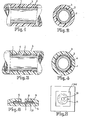
- 1 denotes the steel pipe.
- 2 is the acrylic-ethylene copolymer layer and 3 the subsequent polyethylene coating.
- the steel tube is also identified by 1 in FIGS. 3 and 4.
- the thermosetting cross-linked powder layer thermally melted into a film is designated by 4.
- the acrylic / ethylene copolymer layer 2 and the polyethylene sheathing 3 are then arranged thereon.
- the entire structure is produced in such a way that a steel tube passes through a heating device in which it is heated to 250.degree.
- the thermosetting powder is then applied using a suitable electrostatic application device.
- An extruded film strip made of acrylic-ethylene copolymer is then wound onto the hardening layer and then an extruded film strip made of polyethylene is then wound up. The whole is pressed onto the pipe surface with an elastic pressure roller and the pipe thus coated is then cooled.
- FIGS. 3 and 4 The structure shown in FIGS. 3 and 4 was compared in a stricter short-term test based on the ASTM test G8-72T (cathodic debonding test) at -1.9 volts with the structure shown in FIGS. 1 and 2. It was found here that the structure shown in FIGS. 1 and 2 had infiltrated to a length of 30 mm after two to three days, while the structure produced by the process according to the invention and shown in FIGS. body only showed an infiltration of less than 6 mm after 30 days.
- FIGS. 5 and 6 show the structure of the test specimens for the comparative test.
- FIG. 6 shows a steel plate 6 inserted in a polyethylene plate 5, which has a hardened powder coating layer 7, an acrylic-ethylene copolymer layer 8 and a polyethylene plate 9.
- the assessment of the test plate is shown in FIG. 5, with the infiltration at the applied voltage of -1.9 volts starting from the bore, which in the example has a diameter of 6 mm and is designated by 10, and measured along the arrow 11 in millimeters becomes.
- the curve denoted by 8 shows the comparison values obtained without the powder coating layer applied according to the invention and the curve denoted by 9 shows the values which were obtained with a casing produced by the method according to the invention and using a first powder coating layer.
- the improvement obtained by the method according to the invention has an effect in practice due to the high level of insensitivity during transport and laying of the pipes as well as by significantly increasing their stability and reliability.
Abstract
Description
Die Erfindung bezieht sich auf ein Verfahren zur Außenbeschichtung eines Metallrohres mit mindestens zwei organischen Verbundschichten und nachfolgenden Polyäthylen-Ummantelung durch Aufbringen mindestens einer zum metallischen Untergrund haftvermittelnden und korrosionsschützenden Schicht und weiteres Aufbringen mindestens einer zum nachfolgenden Polyäthylen haftvermittelnden Schicht.The invention relates to a method for the outer coating of a metal tube with at least two organic composite layers and subsequent polyethylene sheathing by applying at least one layer which promotes adhesion and corrosion protection to the metallic substrate and further application of at least one layer which promotes polyethylene.
Die Ummantelung von Metallrohren mit Polyäthylen erfolgt in der Praxis so, daß das Rohr zunächst eine Schicht aus beispielsweise einem Acryl-Äthylen-Copolymerisat erhält, das als Haftvermittler zwischen dem Metallsubstrat einerseits und der Polyäthylen-Ummantelung andererseits dient. Die Applikation dieser Materialien erfolgt in der Praxis auf verschiedene Weise, z.B. durch das Pulver-Aufstreu-Verfahren, durch Schlauchextrusion oder Folienwickelverfahren. Es können auch Kombinationen aus diesen Applikationsverfahren angewendet werden.The coating of metal pipes with polyethylene is done in practice so that the pipe first receives a layer of, for example, an acrylic-ethylene copolymer, which serves as an adhesion promoter between the metal substrate on the one hand and the polyethylene coating on the other. In practice, these materials are applied in various ways, e.g. by the powder-litter method, by tube extrusion or foil winding method. Combinations of these application methods can also be used.
Mit diesen praxisüblichen Verbundaufbauten läßt sich jedoch kein befriedigender Korrosionsschutz und keine ausreichende Dauerhaftung bei Korrosionsbeanspruchung und bei einer Beschädigung der Ummantelung erreichen. Das bedeutet, daß die in der Praxis eingesetzte Ummantelung gegen bei Transport und Verlegung unvermeidbar auftretende Beschädigungen empfindlich ist.With these common composite structures, however, satisfactory corrosion protection and insufficient permanent adhesion in the event of corrosion and damage to the casing cannot be achieved. This means that the sheathing used in practice is sensitive to damage inevitably occurring during transport and laying.
Aufgabe der Erfindung war es, unter Vermeidung der obigen Nachteile ein verbessertes Verfahren mit höherem Korrosionsschutz und verbesserter Dauerhaftung bei Korrosionsbeanspruchung zu schaffen.The object of the invention was to provide an improved method with higher corrosion protection and improved long-term adhesion under corrosion stress while avoiding the above disadvantages.
Diese Aufgabe wird gelöst durch ein Verfahren zur Außenbeschichtung eines Metallrohres mit mindestens zwei organischen Verbundschichten und nachfolgenden Polyäthylen-Ummantelung durch Aufbringen mindestens einer zum metallischen Untergrund haftvermittelnden und korrosionsschützenden Schicht, danach Aufbringen mindestens einer zum nachfolgenden Polyäthylen haftvermittelnden Schicht, das dadurch gekennzeichnet ist, daß die zum metallischen Untergrund haftvermittelnde Schicht als Pulver auf das vorerhitzte Metallrohr aufgebracht wird und dort thermisch zu einem Film aufschmilzt und dabei duroplastisch vernetzt.This object is achieved by a process for the external coating of a metal pipe with at least two organic composite layers and subsequent polyethylene sheathing by applying at least one layer which promotes adhesion and corrosion protection to the metallic substrate, then applying at least one layer which promotes the subsequent polyethylene, which is characterized in that the is applied as a powder to the preheated metal pipe to the metallic substrate, where it melts thermally into a film and is crosslinked thermosetly.
Auf diese vernetzende Schicht wird dann die zum nachfolgenden Polyäthylen haftvermittelnde Schicht aufgebracht, die aus an sich bekanntem Acryl-Äthylen-Copolymer besteht.The crosslinking layer is then applied with the layer which provides adhesion to the subsequent polyethylene and which consists of an acrylic / ethylene copolymer which is known per se consists.
..
Ein großer Vorteil des erfindungsgemäßen Verfahrens besteht darin, daß das Pulver, das die zum metallischen Untergrund haftvermittelnde Schicht bildet, mit den bekannten Applikationsgeräten für Pulverlacke aufgebracht werden kann bei einem hohen Wirkungsgrad der durch Zwischenschaltung von Pulverrückgewinnungseinrichtungen eine Materialausbeute von ca. 99 % erreicht.A great advantage of the method according to the invention is that the powder which forms the layer which promotes adhesion to the metallic substrate can be applied with the known application devices for powder coatings, with a high efficiency which, by interposing powder recovery devices, achieves a material yield of approximately 99%.
Als Pulver, das die zum metallischen Untergrund haftvermittelnde Schicht bildet, eignen sich die in der Wärme duroplastisch vernetzenden Pulverlacke auf der Basis von Polyacrylat, Epoxid-, Polyurethan-, Epoxy-Polyester- und Polyesterbindemitteln.The powder that forms the layer that promotes adhesion to the metallic substrate is thermosetting powder coatings based on polyacrylate, epoxy, polyurethane, epoxy polyester and polyester binders.
Besonders gute Ergebnisse werden erhalten und deshalb bevorzugt vorgeschlagen werden Pulverlacke auf der Basis von Epoxidbindemitteln, die als einen in der Wärme wirksam werdenden Vernetzer einen Di-. cyan-Diamid-Härter oder dessen Derivate enthalten.Particularly good results are obtained and therefore powder coatings based on epoxy binders are preferably proposed which act as a crosslinker which acts as a heat crosslinker. Contain cyan diamide hardener or its derivatives.
Hinsichtlich des Korrosionsschutzes und der Haftung nach Beanspruchung werden besonders gute Ergebnisse erhalten mit einem Epoxidharz-Pulverlack auf Basis Bisphenol A, der aufWith regard to corrosion protection and adhesion after stress, particularly good results are obtained with an epoxy resin powder coating based on bisphenol A based on
80 bis 98 Gew.-% Epoxidharz auf Basis Bisphenol A 20 bis 2 Gew.-% Dicyandiamid-Härter oder dessen Derivate enthält, wobei die Summe aus Epoxidharz und Härter stets 100 % beträgt.80 to 98% by weight epoxy resin based on
Zusätzlich können auf 100 % des Epoxidharz-Härtergemisches noch 5 bis 60 Gew.-% Pigmente und/oder Füllstoffe kommen.In addition, 5 to 60% by weight of pigments and / or fillers can be added to 100% of the epoxy resin hardener mixture.
Die Schichtenfolge der Metallrohr-Ummantelung wird durch die Zeichnung dargestellt. Hierbei stellt
Figur 1 einen Längsschnitt durch ein Rohrsegment mit dem.bisher in der Praxis angewendeten Aufbau dar undFigur 2 einen Querschnitt durch das entsprechende Rohr.Figur 3 stellt den Längsschnitt eines Rohrsegmentes mit einem nach dem erfindungsgemäßen Verfahren erhaltenen Aufbau dar undFigur 4 einen entsprechenden Querschnitt durch ein derartig ummanteltes Rohr.
- 1 shows a longitudinal section through a pipe segment with the structure previously used in practice and
- Figure 2 shows a cross section through the corresponding tube.
- Figure 3 shows the longitudinal section of a pipe segment with a structure obtained by the inventive method and
- Figure 4 shows a corresponding cross section through such a jacketed tube.
In den Figuren 1 und 2 ist mit 1 das Stahlrohr bezeichnet. Mit 2 ist die Acryl-Äthylen-Copolymerisat-Schicht und mit 3 die danach folgende Polyäthylen-Ummantelung bezeichnet.In Figures 1 and 2, 1 denotes the steel pipe. 2 is the acrylic-ethylene copolymer layer and 3 the subsequent polyethylene coating.
Auch in den Figuren 3 und 4 ist mit 1 das Stahlrohr gekennzeichnet. Die duroplastisch vernetzte und thermisch zu einem Film aufgeschmolzene Pulverschicht ist mit 4 bezeichnet. Darauf angeordnet ist dann wiederum die Acryl-Äthylen-Copolymerisat-Schicht 2 und die Polyäthylen-Ummantelung 3.The steel tube is also identified by 1 in FIGS. 3 and 4. The thermosetting cross-linked powder layer thermally melted into a film is designated by 4. The acrylic /
Zur Herstellung des gesamten Aufbaus wird in einem Ausführungsbeispiel so verfahren, daß ein Stahlrohr eine Heizeinrichtung durchläuft, in der es bis auf 250°C erwärmt wird. Danach erfolgt das Aufbringen des duroplastisch härtenden Pulvers mittels einer geeigneten elektrostatischen Auftragsvorrichtung. Auf die aushärtende Schicht wird dann ein extrudiertes Folienband aus Acryl-Äthylen-Copolymerisat aufgewickelt und anschließend wird ein ebenfalls extrudiertes Folienband aus Polyäthylen aufgewickelt. Das Ganze wird mit einer elastischen Anpreßrolle auf die Rohroberfläche gedrückt und das so ummantelte Rohr anschließend abgekühlt.In one exemplary embodiment, the entire structure is produced in such a way that a steel tube passes through a heating device in which it is heated to 250.degree. The thermosetting powder is then applied using a suitable electrostatic application device. An extruded film strip made of acrylic-ethylene copolymer is then wound onto the hardening layer and then an extruded film strip made of polyethylene is then wound up. The whole is pressed onto the pipe surface with an elastic pressure roller and the pipe thus coated is then cooled.
Der in den Figuren 3 und 4 abgebildete Aufbau wurde in einer verschärften Kurzzeitprüfung in Anlehnung an den ASTM-Test G8-72T (kathodischer Disbonding-Test) bei -1,9 Volt mit dem in Figur 1 und 2 dargestellten Aufbau verglichen. Hierbei wurde festgestellt, daß der in den Figuren 1 und 2 dargestellte Aufbau nach zwei bis drei Tagen auf 30 mm Länge unterwandert war, während der nach dem erfindungsgemäßen Verfahren hergestellte und in den Figuren 3 und 4 darge-stellte Aufbau erst nach 30 Tagen eine Unterwanderung von weniger als 6 mm zeigte.The structure shown in FIGS. 3 and 4 was compared in a stricter short-term test based on the ASTM test G8-72T (cathodic debonding test) at -1.9 volts with the structure shown in FIGS. 1 and 2. It was found here that the structure shown in FIGS. 1 and 2 had infiltrated to a length of 30 mm after two to three days, while the structure produced by the process according to the invention and shown in FIGS. body only showed an infiltration of less than 6 mm after 30 days.
Den Aufbau der Prüflinge für den vergleichenden Test zeigen die Figuren 5 und 6. In Figur 6 wird eine in einer Polyäthylenplatte 5 eingelegte Stahlplatte 6 gezeigt, die eine gehärtete Pulverlackschicht 7, eine Acryl-Äthylen-Copolymerisatschicht 8 und eine Polyäthylenplatte 9 aufweist. Die Beurteilung der Prüfplatte zeigt Figur 5, wobei bei der angelegten Spannung von -1,9 Volt die Unterwanderung von der Bohrung, die in dem Beispiel einen Durchmesser von 6 mm hat und mit 10 bezeichnet ist, ausgeht und entlang dem Pfeil 11 in Millimeter gemessen wird.FIGS. 5 and 6 show the structure of the test specimens for the comparative test. FIG. 6 shows a
In Figur 7 ist das Ergebnis der Prüfung des verschärften Korrosionstestes nach ASTM G8-72T grafisch dargestellt. Als Ordinate sind die Millimeter Unterwanderung aufgetragen und als Abszisse die Tage Prüfzeit.The result of the test of the tightened corrosion test according to ASTM G8-72T is shown graphically in FIG. The millimeter infiltration is plotted as the ordinate and the days of test time as the abscissa.
Die mit 8 bezeichnete Kurve zeigt die erhaltenen Vergleichswerte ohne erfindungsgemäß aufgebrachte Pulverlackschicht und die mit 9 bezeichnete Kurve zeigt die Werte, die erhalten wurden mit einer nach dem erfindungsgemäßen Verfahren hergestellten Ummantelung und unter Verwendung einer ersten Pulverlackschicht.The curve denoted by 8 shows the comparison values obtained without the powder coating layer applied according to the invention and the curve denoted by 9 shows the values which were obtained with a casing produced by the method according to the invention and using a first powder coating layer.
Die durch das erfindungsgemäße Verfahren erhaltene Verbesserung wirkt sich in der Praxis durch hohe Unempfindlichkeit bei Transport und Verlegung der Rohre aus sowie durch eine wesentliche Erhöhung ihrer Standfestigkeit und Verwendungssicherheit.The improvement obtained by the method according to the invention has an effect in practice due to the high level of insensitivity during transport and laying of the pipes as well as by significantly increasing their stability and reliability.
Claims (5)
Applications Claiming Priority (2)
| Application Number | Priority Date | Filing Date | Title |
|---|---|---|---|
| DE19803046263 DE3046263C2 (en) | 1980-12-09 | 1980-12-09 | Method for sheathing a metal pipe |
| DE3046263 | 1980-12-09 |
Publications (1)
| Publication Number | Publication Date |
|---|---|
| EP0054210A1 true EP0054210A1 (en) | 1982-06-23 |
Family
ID=6118644
Family Applications (1)
| Application Number | Title | Priority Date | Filing Date |
|---|---|---|---|
| EP81109982A Withdrawn EP0054210A1 (en) | 1980-12-09 | 1981-11-28 | Process for coating metallic tubes |
Country Status (3)
| Country | Link |
|---|---|
| EP (1) | EP0054210A1 (en) |
| DE (1) | DE3046263C2 (en) |
| ES (1) | ES507823A0 (en) |
Cited By (3)
| Publication number | Priority date | Publication date | Assignee | Title |
|---|---|---|---|---|
| EP0183930A1 (en) * | 1984-12-06 | 1986-06-11 | Hoesch Aktiengesellschaft | Production process for a metal pipe with a corrosion and shock protecting layer |
| EP0698422A1 (en) * | 1994-06-22 | 1996-02-28 | Bayer Ag | Procedure for insulation of pipes |
| EP0822012A1 (en) * | 1996-07-30 | 1998-02-04 | Elf Atochem S.A. | Coating on metallic surfaces and use on tubes and cables |
Families Citing this family (5)
| Publication number | Priority date | Publication date | Assignee | Title |
|---|---|---|---|---|
| DE3229563A1 (en) * | 1982-08-07 | 1984-02-23 | Hoechst Ag, 6230 Frankfurt | METHOD FOR COATING METAL SUBSTRATES AND USE OF PRODUCTS PRODUCED BY THIS METHOD |
| GB2145639A (en) * | 1983-08-25 | 1985-04-03 | Shaw Ind Ltd | Impact-resistant, moisture-impermeable resinous coatings and method of applying the same to an object |
| JP2709483B2 (en) * | 1988-09-17 | 1998-02-04 | 臼井国際産業株式会社 | Coating method for coated metal tubing |
| DE19843375C2 (en) | 1998-09-10 | 2003-02-13 | Sedra Asphalt Technik Biebrich | Insulating sheathing for tie rods |
| CN108692134B (en) * | 2018-07-06 | 2023-09-26 | 辽宁凌勃防腐工程科技有限公司 | Internal and external double-corrosion-resistant plastic-coated composite pipe and one-step forming process thereof |
Citations (2)
| Publication number | Priority date | Publication date | Assignee | Title |
|---|---|---|---|---|
| DE2020901A1 (en) * | 1969-09-15 | 1971-05-13 | Continental Can Co | Process for the production of metal objects and metal objects with a surface coated with polyethylene |
| FR2252187A1 (en) * | 1973-11-22 | 1975-06-20 | Mitsui Petrochemical Ind |
-
1980
- 1980-12-09 DE DE19803046263 patent/DE3046263C2/en not_active Expired
-
1981
- 1981-11-28 EP EP81109982A patent/EP0054210A1/en not_active Withdrawn
- 1981-12-09 ES ES507823A patent/ES507823A0/en active Granted
Patent Citations (2)
| Publication number | Priority date | Publication date | Assignee | Title |
|---|---|---|---|---|
| DE2020901A1 (en) * | 1969-09-15 | 1971-05-13 | Continental Can Co | Process for the production of metal objects and metal objects with a surface coated with polyethylene |
| FR2252187A1 (en) * | 1973-11-22 | 1975-06-20 | Mitsui Petrochemical Ind |
Cited By (6)
| Publication number | Priority date | Publication date | Assignee | Title |
|---|---|---|---|---|
| EP0183930A1 (en) * | 1984-12-06 | 1986-06-11 | Hoesch Aktiengesellschaft | Production process for a metal pipe with a corrosion and shock protecting layer |
| EP0698422A1 (en) * | 1994-06-22 | 1996-02-28 | Bayer Ag | Procedure for insulation of pipes |
| US5534299A (en) * | 1994-06-22 | 1996-07-09 | Bayer Aktiengsellschaft | Process for insulating pipes |
| EP0822012A1 (en) * | 1996-07-30 | 1998-02-04 | Elf Atochem S.A. | Coating on metallic surfaces and use on tubes and cables |
| US5993924A (en) * | 1996-07-30 | 1999-11-30 | Elf Atochem S. A. | Coating of metal surfaces, its application to tubes and to cables |
| US6291024B1 (en) | 1996-07-30 | 2001-09-18 | Elf Atochem S.A. | Coating of metal surfaces, its application to tubes and to cables |
Also Published As
| Publication number | Publication date |
|---|---|
| DE3046263C2 (en) | 1982-12-09 |
| ES8305601A1 (en) | 1983-04-16 |
| ES507823A0 (en) | 1983-04-16 |
| DE3046263A1 (en) | 1982-06-16 |
Similar Documents
| Publication | Publication Date | Title |
|---|---|---|
| EP0100992A2 (en) | Coating method for metallic substrates, and use of the so coated objects | |
| DE3247510C2 (en) | Process for encasing a shaped body and application of the process to a shaped body with a heat-sensitive inner layer | |
| DE3046263C2 (en) | Method for sheathing a metal pipe | |
| DE19531708A1 (en) | Corrosion resistant resin coating assembly on a metal tube | |
| EP0178404B1 (en) | Metal pipe with protection against corrosion and method for its production | |
| DE2923544A1 (en) | Tube with fibre-reinforced polyamide layers - has steel envelope drawn and bonded by epoxy! accelerator to polyamide | |
| DE2832235C3 (en) | Process for direct bonding of rubber to metal surfaces | |
| DE2255084B2 (en) | Composite pipe and process for its manufacture | |
| EP0057823A2 (en) | Coating method for metal pipes and use of such pipes | |
| EP0679853B1 (en) | Coating for end plates and heat exchanger tubes for cooling medium | |
| EP0054209A1 (en) | Process for coating metal tubes | |
| EP0268547A1 (en) | Method for enveloping steel objects with plastics | |
| DE3825200C1 (en) | Process for coating plastic components with metals | |
| DE19515234A1 (en) | Metal parts with a corrosion protection layer | |
| EP0198144A1 (en) | Method for enveloping a steel pipe | |
| DE8320528U1 (en) | CORROSION PROTECTED TUBE WITH MECHANICAL PROTECTIVE LAYER | |
| AT243039B (en) | Method for producing protective coatings on metallic workpieces | |
| DE3512528C2 (en) | ||
| DE102007022143B4 (en) | Process for producing a sandwich structure for use as armor against ballistic projectiles, in particular hollow charges | |
| DE2702064C2 (en) | Corrosion-protected coated metal tube | |
| DE3508811A1 (en) | Process for covering a steel pipe | |
| DE3741627C1 (en) | Process for the continuous sheathing of steel pipes with plastic | |
| EP0360755B1 (en) | Single or multi-care insulated electrical conductors, and process for manufacturing the same | |
| EP3362700A1 (en) | Coated spring | |
| DE102012007203B4 (en) | Method and device for increasing the output of a shaped charge with plastic-bonded explosive at low temperatures |
Legal Events
| Date | Code | Title | Description |
|---|---|---|---|
| PUAI | Public reference made under article 153(3) epc to a published international application that has entered the european phase |
Free format text: ORIGINAL CODE: 0009012 |
|
| AK | Designated contracting states |
Designated state(s): AT BE CH DE FR GB IT NL SE |
|
| 17P | Request for examination filed |
Effective date: 19820510 |
|
| STAA | Information on the status of an ep patent application or granted ep patent |
Free format text: STATUS: THE APPLICATION HAS BEEN WITHDRAWN |
|
| 18W | Application withdrawn |
Withdrawal date: 19831125 |
|
| RIN1 | Information on inventor provided before grant (corrected) |
Inventor name: LINDNER, WERNER Inventor name: PIESER, HORST Inventor name: DORS, BERNHARD, DR. Inventor name: KOPKA, GEORG |