EP0053952A1 - Installation for the incineration of wastes and heat recovery - Google Patents
Installation for the incineration of wastes and heat recovery Download PDFInfo
- Publication number
- EP0053952A1 EP0053952A1 EP81401698A EP81401698A EP0053952A1 EP 0053952 A1 EP0053952 A1 EP 0053952A1 EP 81401698 A EP81401698 A EP 81401698A EP 81401698 A EP81401698 A EP 81401698A EP 0053952 A1 EP0053952 A1 EP 0053952A1
- Authority
- EP
- European Patent Office
- Prior art keywords
- recuperator
- oven
- heat
- furnace
- installation according
- Prior art date
- Legal status (The legal status is an assumption and is not a legal conclusion. Google has not performed a legal analysis and makes no representation as to the accuracy of the status listed.)
- Granted
Links
- 239000002699 waste material Substances 0.000 title claims abstract description 21
- 238000009434 installation Methods 0.000 title claims description 23
- 238000011084 recovery Methods 0.000 title claims description 16
- 239000012530 fluid Substances 0.000 claims abstract description 16
- 238000002485 combustion reaction Methods 0.000 claims abstract description 11
- 238000000197 pyrolysis Methods 0.000 claims abstract description 7
- 239000003517 fume Substances 0.000 claims description 22
- 239000013529 heat transfer fluid Substances 0.000 claims description 20
- 238000011282 treatment Methods 0.000 claims description 7
- XLYOFNOQVPJJNP-UHFFFAOYSA-N water Substances O XLYOFNOQVPJJNP-UHFFFAOYSA-N 0.000 claims description 7
- 229910052751 metal Inorganic materials 0.000 claims description 5
- 238000000034 method Methods 0.000 abstract description 6
- 239000000779 smoke Substances 0.000 description 8
- 239000002956 ash Substances 0.000 description 4
- 239000000203 mixture Substances 0.000 description 4
- 239000011819 refractory material Substances 0.000 description 4
- 239000002440 industrial waste Substances 0.000 description 3
- 235000002918 Fraxinus excelsior Nutrition 0.000 description 2
- 238000006243 chemical reaction Methods 0.000 description 2
- 238000000576 coating method Methods 0.000 description 2
- 238000010438 heat treatment Methods 0.000 description 2
- 238000009413 insulation Methods 0.000 description 2
- UGFAIRIUMAVXCW-UHFFFAOYSA-N Carbon monoxide Chemical compound [O+]#[C-] UGFAIRIUMAVXCW-UHFFFAOYSA-N 0.000 description 1
- 238000010521 absorption reaction Methods 0.000 description 1
- QVGXLLKOCUKJST-UHFFFAOYSA-N atomic oxygen Chemical compound [O] QVGXLLKOCUKJST-UHFFFAOYSA-N 0.000 description 1
- 239000011248 coating agent Substances 0.000 description 1
- 230000000295 complement effect Effects 0.000 description 1
- 230000007423 decrease Effects 0.000 description 1
- 239000003546 flue gas Substances 0.000 description 1
- 239000000446 fuel Substances 0.000 description 1
- 238000004519 manufacturing process Methods 0.000 description 1
- 239000000463 material Substances 0.000 description 1
- 239000001301 oxygen Substances 0.000 description 1
- 229910052760 oxygen Inorganic materials 0.000 description 1
- 238000005381 potential energy Methods 0.000 description 1
- 238000007789 sealing Methods 0.000 description 1
- 238000001179 sorption measurement Methods 0.000 description 1
- 230000008646 thermal stress Effects 0.000 description 1
- 239000002562 thickening agent Substances 0.000 description 1
- 238000004056 waste incineration Methods 0.000 description 1
Images


Classifications
-
- F—MECHANICAL ENGINEERING; LIGHTING; HEATING; WEAPONS; BLASTING
- F22—STEAM GENERATION
- F22B—METHODS OF STEAM GENERATION; STEAM BOILERS
- F22B31/00—Modifications of boiler construction, or of tube systems, dependent on installation of combustion apparatus; Arrangements of dispositions of combustion apparatus
- F22B31/04—Heat supply by installation of two or more combustion apparatus, e.g. of separate combustion apparatus for the boiler and the superheater respectively
- F22B31/045—Steam generators specially adapted for burning refuse
-
- F—MECHANICAL ENGINEERING; LIGHTING; HEATING; WEAPONS; BLASTING
- F23—COMBUSTION APPARATUS; COMBUSTION PROCESSES
- F23G—CREMATION FURNACES; CONSUMING WASTE PRODUCTS BY COMBUSTION
- F23G5/00—Incineration of waste; Incinerator constructions; Details, accessories or control therefor
- F23G5/44—Details; Accessories
- F23G5/46—Recuperation of heat
-
- F—MECHANICAL ENGINEERING; LIGHTING; HEATING; WEAPONS; BLASTING
- F23—COMBUSTION APPARATUS; COMBUSTION PROCESSES
- F23G—CREMATION FURNACES; CONSUMING WASTE PRODUCTS BY COMBUSTION
- F23G2203/00—Furnace arrangements
- F23G2203/20—Rotary drum furnace
- F23G2203/205—Rotary drum furnace with water-cooled wall
-
- Y—GENERAL TAGGING OF NEW TECHNOLOGICAL DEVELOPMENTS; GENERAL TAGGING OF CROSS-SECTIONAL TECHNOLOGIES SPANNING OVER SEVERAL SECTIONS OF THE IPC; TECHNICAL SUBJECTS COVERED BY FORMER USPC CROSS-REFERENCE ART COLLECTIONS [XRACs] AND DIGESTS
- Y02—TECHNOLOGIES OR APPLICATIONS FOR MITIGATION OR ADAPTATION AGAINST CLIMATE CHANGE
- Y02E—REDUCTION OF GREENHOUSE GAS [GHG] EMISSIONS, RELATED TO ENERGY GENERATION, TRANSMISSION OR DISTRIBUTION
- Y02E20/00—Combustion technologies with mitigation potential
- Y02E20/12—Heat utilisation in combustion or incineration of waste
-
- Y—GENERAL TAGGING OF NEW TECHNOLOGICAL DEVELOPMENTS; GENERAL TAGGING OF CROSS-SECTIONAL TECHNOLOGIES SPANNING OVER SEVERAL SECTIONS OF THE IPC; TECHNICAL SUBJECTS COVERED BY FORMER USPC CROSS-REFERENCE ART COLLECTIONS [XRACs] AND DIGESTS
- Y02—TECHNOLOGIES OR APPLICATIONS FOR MITIGATION OR ADAPTATION AGAINST CLIMATE CHANGE
- Y02P—CLIMATE CHANGE MITIGATION TECHNOLOGIES IN THE PRODUCTION OR PROCESSING OF GOODS
- Y02P80/00—Climate change mitigation technologies for sector-wide applications
- Y02P80/10—Efficient use of energy, e.g. using compressed air or pressurized fluid as energy carrier
- Y02P80/15—On-site combined power, heat or cool generation or distribution, e.g. combined heat and power [CHP] supply
Definitions
- the present invention essentially aims to increase the overall energy conversion efficiency by improving the energy recovery between the furnace and the recuperator, but also to improve the conditions of the combustion of waste carried out in the furnace and reduce the cost of material equipment, all of these advantages contributing to optimal recovery of industrial waste in energy production.
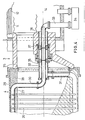
- the tubes 16 are directly in contact with the smoke when they are arranged around the fixed device 3 at the connection between the rotating part and the boiler. To this end, the tubes are arranged almost contiguous and they are connected externally to each other by welded sheet metal elements 20. These elements and the tubes conform to the shape useful for the flue which decreases in section from the outlet of the rotating part 4 to the inlet of the boiler. A thickness of insulating refractory material can however be placed inside the smoke-tight duct. On the outside of the envelope formed essentially by the tubes 16, an external covering 22 is provided which can be insulated to limit the thermal conditions.
Landscapes
- Engineering & Computer Science (AREA)
- Mechanical Engineering (AREA)
- Combustion & Propulsion (AREA)
- Chemical & Material Sciences (AREA)
- General Engineering & Computer Science (AREA)
- Physics & Mathematics (AREA)
- Thermal Sciences (AREA)
- Incineration Of Waste (AREA)
- Processing Of Solid Wastes (AREA)
- Waste-Gas Treatment And Other Accessory Devices For Furnaces (AREA)
- Gasification And Melting Of Waste (AREA)
- Investigation Of Foundation Soil And Reinforcement Of Foundation Soil By Compacting Or Drainage (AREA)
- Processing And Handling Of Plastics And Other Materials For Molding In General (AREA)
- Paper (AREA)
- Fertilizers (AREA)
Abstract
Description
La présente invention a pour objet un procédé de traitement de déchets, ainsi qu'une installation de traitement de déchets convenant à la mise en oeuvre de ce procédé. Elle s'applique plus précisément aux traitements thermiques que l'on fait subir à des déchets industriels en vue d'une récupération d'énergie et qui consiste essentiellement à provoquer la combustion et/ou la pyrolyse des déchets dans un four d'incinération et à récupérer la chaleur produite dans le four en assurant un échange thermique entre les fumées issues du four et un fluide d'utilisation de la chaleur ainsi récupérée.The present invention relates to a waste treatment process, as well as a waste treatment installation suitable for the implementation of this process. It applies more precisely to the heat treatments which are subjected to industrial waste with a view to recovering energy and which essentially consists in causing the combustion and / or pyrolysis of the waste in an incineration oven and recovering the heat produced in the oven by ensuring a heat exchange between the fumes from the oven and a heat utilization fluid thus recovered.
Dans un brevet antérieur de la demanderesse, déposé le 4 décembre 1978 sous le n° 78 34.096, on a décrit un tel procédé, ainsi qu'une installation pour le traitement de déchets qui est essentiellement constituée par un four d'incinération et un récupérateur, ou récepteur de chaleur sensible, disposé sur le circuit des fumées sortant du four. Dans ce genre d'installation et comme décrit dans le brevet cité, le four et le récupérateur sont directement disposés à proximité immédiate l'un de l'autre sur le circuit des fumées, le récupérateur peut être constitué en particulier par une chaudière à vapeur, et le four d'incinération est le plus souvent du type tournant, c'est-à-dire qu'il comporte au moins une partie tournante dans laquelle s'effectue l'essentiel de la combustion (avec éventuellement pyrolyse) et une partie fixe qui assure le guidage des fumées depuis la partie tournante jusqu'à l'entrée dans le récupérateur. C'est avantageusement au niveau de cette partie fixe que l'on assure l'élimination des cendres, ainsi que, le cas échéant, une post-combustion des fumées.In a previous patent of the applicant, filed on December 4, 1978 under the number 78 34.096, there has been described such a process, as well as an installation for the treatment of waste which essentially consists of an incineration oven and a recuperator. , or sensitive heat receiver, placed on the smoke circuit leaving the oven. In this type of installation and as described in the cited patent, the oven and the recuperator are directly disposed in close proximity to one another on the flue gas circuit, the recuperator can be constituted in particular by a steam boiler , and the incineration furnace is most often of the rotary type, that is to say that it comprises at least one rotary part in which most of the combustion takes place (with possibly pyrolysis) and a part fixed which guides the smoke from the rotating part to the entry into the recuperator. It is advantageously at this fixed part that the ash is removed, as well as, if necessary, a post-combustion of the fumes.
Par rapport à cet état de la technique connue, la présente invention vise essentiellement à augmenter le rendement de conversion énergétique global en améliorant la récupération d'énergie entre le four et le récupérateur, mais aussi à améliorer les conditions de la combustion des déchets réalisée dans le four et à diminuer le coût de l'équipement matériel, l'ensemble de ces avantages contribuant à une valorisation optimale des déchets industriels dans la production d'énergie.Compared to this known state of the art, the present invention essentially aims to increase the overall energy conversion efficiency by improving the energy recovery between the furnace and the recuperator, but also to improve the conditions of the combustion of waste carried out in the furnace and reduce the cost of material equipment, all of these advantages contributing to optimal recovery of industrial waste in energy production.
Dans le procédé de traitement de déchets déjà rappelé, suivant lequel on provoque la combustion et/ou la pyrolyse des déchets dans un four d'incinération et l'on fait circuler les fumées produites à la sortie de ce four dans un récupérateur, où ; elles circulent en situation d'échange thermique avec un fluide d'utilisation de la chaleur ainsi récupérée, ledit four comportant au moins une partie tournante et une partie fixe de guidage des fumées de la partie tournante au récupérateur, l'invention réside essentiellement dans le fait que l'on assure en outre une circulation d'un fluide caloporteur entre les parois limitant ladite partie fixe et/ou ladite partie tournante du four, où il absorbe de la chaleur des fumées situées dans le four, et le récupérateur où il cède cette chaleur au fluide d'utilisation.In the waste treatment process already mentioned, according to which the combustion and / or pyrolysis of the waste in an incineration oven and the fumes produced at the outlet of this oven are circulated in a recuperator, where; they circulate in a heat exchange situation with a fluid for using the heat thus recovered, said oven comprising at least one rotating part and a fixed part for guiding the fumes from the rotating part to the recuperator, the invention essentially resides in the the fact that circulation of a heat-transfer fluid is also ensured between the walls limiting said fixed part and / or said rotary part of the oven, where it absorbs heat from the fumes located in the oven, and the recuperator where it yields this heat to the operating fluid.
c e Une installation de traitement de déchets selon l'invention, permettant la mise en oeuvre du procédé ci-dessus, comportè essentiellement un four d'incinération comportant au moins une partie tournante pour la combustion et/ou la pyrolyse des déchets et une partie fixe de guidage des fumées produites dans le four entre la partie tournante et un récupérateur comportant des moyens pour faire circuler les fumées en situation d'échange thermique avec un fluide d'utilisation de la chaleur ainsi récupérée. Elle comporte en outre des moyens pour faire circuler un fluide caloporteur entre les parois limitant ladite partie fixe et/ou ladite partie tournante du four et le récupérateur, de manière que le fluide caloporteur cède au fluide d'utilisation dans le récupérateur la chaleur qu'il a absorbée dans son passage dans les parois du four.ce A waste treatment installation according to the invention, allowing the implementation of the above process, essentially comprises an incineration furnace comprising at least one rotating part for the combustion and / or pyrolysis of the waste and a fixed part for guiding the fumes produced in the furnace between the rotating part and a recuperator comprising means for circulating the fumes in a heat exchange situation with a heat utilization fluid thus recovered. It further comprises means for circulating a heat transfer fluid between the walls limiting said fixed part and / or said rotary part of the furnace and the recuperator, so that the heat transfer fluid gives up the heat that in use in the recuperator. it absorbed in its passage through the walls of the oven.
L'invention ainsi définie peut être mise en oeuvre sous différentes formes de réalisation plus particulières.The invention thus defined can be implemented in different more specific embodiments.
Quelle que soit la réalisation pratique des conduits du fluide caloporteur au niveau des parois du four, l'ensemble du circuit qui guide le fluide caloporteur du récupérateur aux parois du four et de ces parois au récupérateur en retour, peut être conçu de manière à y assurer une circulation thermique naturelle provoquée par les variations de température que subit le fluide caloporteur. Mais l'on peut aussi préférer assurer une circulation forcée au moyen d'une pompe. D'autre part, le fluide caloporteur peut être constitué par un fluide quelconque, choisi pour ses qualités de transfert thermique, que l'on fait circuler en boucle dans un circuit fermé allant des parois du four au fluide d'utilisation contenu dans le récupérateur. Dans d'autres cas, il peut s'agir du même fluide que le fluide d'utilisation circulant dans le récupérateur, et le fluide caloporteur peut alors avantageusement être prélevé directement dans le fluide d'utilisation contenu dans le récupérateur, par exemple dans la masse d'une chaudière à vapeur chauffée par circulation des fumées, et y être retourné après échauffement dans les parois du four.Whatever the practical embodiment of the heat transfer fluid conduits at the walls of the furnace, the entire circuit which guides the heat transfer fluid from the recuperator to the walls of the furnace and from these walls to the recuperator in return, can be designed so that there ensure a natural thermal circulation caused by the temperature variations undergone by the heat transfer fluid. However, it may also be preferable to provide forced circulation by means of a pump. On the other hand, the heat transfer fluid can be constituted by any fluid, chosen for its thermal transfer qualities, which is made to circulate in a loop in a closed circuit going from the walls of the furnace to the fluid of use contained. in the recuperator. In other cases, it may be the same fluid as the operating fluid circulating in the recuperator, and the heat transfer fluid may then advantageously be taken directly from the operating fluid contained in the recuperator, for example in the mass of a steam boiler heated by smoke circulation, and to be returned there after heating in the walls of the oven.
Au niveau du four, on préfère en général réaliser la récupération supplémentaire de chaleur par le fluide caloporteur au moins dans les parois de tous les éléments fixes du four en contact avec les fumées, soit d'une part la partie fixe qui guide les fumées du four au récupérateur, mais aussi d'autre part la façade fixe du four où sont montés en pratique le brûleur et le dispositif d'alimentation en déchets, à l'opposé du récupérateur. Sur ces éléments fixes, les conduits qui guident la circulation du fluide caloporteur peuvent remplacer, au moins en grande partie, les matériaux réfractaires qui assurent habituellement l'isolation thermique du four, et ils peuvent avantageusement être disposés de manière à constituer eux-mêmes directement l'enveloppe qui ferme le volume occupé par les fumées.At the level of the oven, it is generally preferred to carry out the additional heat recovery by the heat-transfer fluid at least in the walls of all the fixed elements of the oven in contact with the fumes, that is on the one hand the fixed part which guides the fumes of the furnace to the recuperator, but also on the other hand the fixed front of the furnace where the burner and the waste supply device are mounted in practice, opposite the recuperator. On these fixed elements, the conduits which guide the circulation of the heat transfer fluid can replace, at least in large part, the refractory materials which usually provide thermal insulation of the furnace, and they can advantageously be arranged so as to constitute themselves directly the envelope which closes the volume occupied by the fumes.
Dans une autre forme de mise en oeuvre de l'invention, le fluide caloporteur est mis en circulation au moins dans les parois de la partie tournante du four. La réalisation est alors particulièrement simple du point de vue mécanique si les conduits de fluide caloporteur restent fixes. Ils sont alors disposés pour constituer une enveloppe externe fixe, à l'extérieur d'une enveloppe interne tournante qui limite le volume occupé par les fumées, mais au voisinage immédiat de cette dernière, de manière à permettre le transfert thermique. Les conduits situés autour de la partie tournante du four peuvent être branchés sur un même circuit de fluide caloporteur en parallèle avec d'autres conduits fixes constituant directement l'enveloppe des fumées, dans les parties fixes du four. Cependant, il peut être préférable de concevoir la circulation du fluide caloporteur de manière à assurer la meilleure récupération thermique possible même au niveau de la partie tournante du four et même aux dépens de la simplicité mécanique. Dans cette optique, on peut constituer l'enveloppe interne tournante limitant le volume occupé par les fumées directement par les conduits du fluide caloporteur, disposés pour être quasiment jointifs et reliés entre eux par des éléments d'étanchéité appropriés, et l'on peut brancher ces conduits en parallèle entre un distributeur et un collecteur disposés coaxialement l'un dans l'autre sur l'axe de la partie tournante pour assurer la continuité du circuit avec des éléments fixes dans le récupérateur.In another embodiment of the invention, the heat transfer fluid is circulated at least in the walls of the rotary part of the furnace. The realization is then particularly simple from the mechanical point of view if the heat transfer fluid conduits remain fixed. They are then arranged to constitute a fixed external envelope, outside a rotating internal envelope which limits the volume occupied by the fumes, but in the immediate vicinity of the latter, so as to allow heat transfer. The conduits located around the rotating part of the furnace can be connected to the same heat transfer fluid circuit in parallel with other fixed conduits directly constituting the smoke casing, in the fixed parts of the furnace. However, it may be preferable to design the circulation of the heat transfer fluid so as to ensure the best possible heat recovery even at the rotating part of the oven and even at the expense of mechanical simplicity. In this context, we can form the rotating internal envelope limiting the volume occupied by the fumes directly by the heat transfer fluid conduits, arranged to be almost contiguous and connected together by suitable sealing elements, and these conduits can be connected in parallel between a distributor and a collector arranged coaxially one in the other on the axis of the rotating part to ensure the continuity of the circuit with fixed elements in the recuperator.
Dans tous les cas les enveloppes de fumées, constituées par les conduits de fluide caloporteur, peuvent être doublées, intérieurement ou extérieurement, ou les deux, de revêtements réfractaires isolants qui n'ont alors pas besoin d'être étanches aux fumées.In all cases the smoke envelopes, formed by the heat transfer fluid conduits, can be lined, internally or externally, or both, with refractory insulating coatings which then do not need to be smoke-tight.
On décrira maintenant plus en détail deux modes de réalisation particuliers de l'installation selon l'invention, choisis à titre d'exemples non limitatifs, et décrits en se référant aux dessins annexés dans lesquels :
- - la figure 1 représente schématiquement une installation selon l'invention, en coupe transversale partielle, dans une première forme de réalisation;
- - la figure 2 représente un détail de cette installatim, au niveau de la partie fixe du four d'incinération des déchets;
- - la figure 3 représente la façade du four, dans une vue selon la flèche III de la figure 1; et
- - la figure 4 illustre une autre forme de réalisation d'une installation selon l'invention, dont elle montre seulement une partie dans une coupe transversale partielle.
- - Figure 1 schematically shows an installation according to the invention, in partial cross section, in a first embodiment;
- - Figure 2 shows a detail of this installation, at the fixed part of the waste incineration oven;
- - Figure 3 shows the front of the oven, in a view along arrow III of Figure 1; and
- - Figure 4 illustrates another embodiment of an installation according to the invention, of which it shows only a part in a partial cross section.
L'installation de la figure 1 est destinée, conformément à l'invention, au traitement de déchets industriels en vue de la production d'énergie par la combustion et éventuellement la pyrolyse de ces déchets. Elle comprend essentiellement un four d'incinération 1, du type rotatif, et comme récupérateur, une chaudière à vapeur 2, directement accouplée derrière le four sur le trajet des fumées, par un dispositif de liaison 3 qui est considéré comme un élément fixe faisant partie du four.The installation of FIG. 1 is intended, in accordance with the invention, for the treatment of industrial waste with a view to producing energy by the combustion and possibly the pyrolysis of this waste. It essentially comprises an incineration oven 1, of the rotary type, and as a recuperator, a
La représentation des dessins rappelle schématiquement la conception du four 1 et de la chaudière 2 dans ce qu'elle a de classique. En ce qui concerne le four 1, on voit apparaître sur la figure 1 la partie tournante 4, ouverte en aval sur le dispositif de liaison 3 et fermée à l'extrémité opposée par un élément de façade 5 qui est fixe. Un dispositif d'alimentation 6 permet d'introduire les déchets à brûler dans le four à travers l'élément de façade 5. Ce dernier est également traversé par un brûleur 7 alimenté en air et oxygène. Un moteur 9 permet d'entraîner la partie tournante 4 en rotation autour de son axe par l'intermédiaire de galets à friction. Un bâti 8 supporte l'ensemble du four en position inclinée par rapport au sol, de sorte que les cendres restant après la combustion des déchets s'écoulent progressivement en direction de la partie fixe du four où il est prévu une vanne d'extraction de ces cendres, 10. Pour ce qui concerne la chaudière 2, le dessin montre le conduit à paroi ondulée 11 qui prolonge à l'intérieur de la chaudière la sortie des fumées du four, et les faisceaux tubulaires 12 dans lesquels les fumées circulent ensuite avant d'être évacuées par la sortie 13. Dans cette chaudière, la chaleur sensible des fumées est récupérée pour chauffer et vaporiser de l'eau 14. La vapeur produite, ou le mélange eau-vapeur,peut 3he considéré comme un fluide d'utilisation qui permet de véhiculer l'énergie ainsi récupérée à l'extérieur de l'installation et jusqu'au lieu d'utilisation.The representation of the drawings schematically recalls the design of the furnace 1 and of the
Conformément à l'invention, il est prévu de dériver une partie du mélange eau-vapeur dans un circuit de récupération thermique complémentaire comportant des conduits qui sont intégrés dans les parois du four 1 pour absorber directement à ce niveau une partie de la chaleur des fumées produites dans le four. On a fait figurer des conduits de ce genre en 15 (figure 1) autour de la partie tournante 4 du four, en 16 (figures 1 et 2) autour du dispositif de liaison fixe 3, et en 17 (figure 3) contre l'élément de façade 5. Tous ces conduits sont constitués par des tubes qui sont branchés en parallèle sur des collecteurs communs, lesquels comprennent plus précisément un distributeur d'alimentation 18, ouvert dans la masse d'eau 14 à l'intérieur de la chaudière 2, et un collecteur 19 qui débouche dans la partie haute de la chaudière. L'eau, ou le mélange eau-vapeur, à la même pression que celle qui règne dans la chaudière, traverse le circuit de récupération en circulation thermique naturelle. Le distributeur 18 longe le four 1 suivant sa génératrice inférieure, en se dédoublant pour contourner le système d'évacuation des cendres 10 et les galets du système d'entraînement de la partie tournante 4. Le collecteur 19 longe le four de la même manière, mais à son extrémité supérieure.According to the invention, it is planned to divert part of the water-steam mixture in a complementary heat recovery circuit comprising conduits which are integrated in the walls of the furnace 1 to directly absorb at this level part of the heat of the fumes produced in the oven. Ducts of this type have been shown at 15 (FIG. 1) around the
Autour de la partie tournante 4 du four, les tubes 15 sont disposés côte à côte entre le distributeur 18 et le collecteur 19, en demi-cercles de part et d'autre du four. Ils sont situé aussi près que possible du cylindre rotatif 21 qui forme l'enveloppe interne étanche aux fumées. Sur la figure 1 on a représenté ce cylindre revêtu d'une épaisseur de matériau réfractaire isolant.Around the
Par contre, les tubes 16 sont directement en contact avec les fumées lorsqu'ils sont disposés autour du dispositif fixe 3 à la liaison entre la partie tournante et la chaudière. A cet effet, les tubes sont disposés quasiment jointifs et ils sont reliés extérieurement entre eux par des éléments de tôle 20 soudés. Ces éléments et les tubes épousent la forme utile pour le conduit des fumées qui va en diminuant de section depuis la sortie de la partie tournante 4 jusqu'à l'entrée dans la chaudière. Une épaisseur de matériau réfractaire isolant peut cependant être disposée à l'intérieur du conduit étanche aux fumées. A l'extérieur de l'enveloppe formée essentiellement par les tubes 16, on a prévu un habillage externe 22 qui peut être calorifugé pour limiter les d4er- ditions thermiques.By cons, the
L'élément de façade 5 étant également une partie fixe du four, l'enveloppe étanche aux fumées y est constituée de la même manière directement par les tubes 17 (figure 3), dont les parois sont reliées entre elles par des éléments de tôle soudés. Les tubes 17 sont branchés en parallèle sur deux collecteurs 23 et 24, en forme d'arc de cercle, dans lesquels débouchent respectivement le distributeur 18 et le collecteur 19. Ces tubes sont conformés de manière à contourner les ouvertures 25 et 26 ménagées à travers l'élément de façade pour permettre le passage du brûleur et du dispositif d'alimentation en déchets respectivement. Les éléments de tôle soudés entre les tubes complètent la fermeture vis-à-vis des fumées dans tout le cercle de la façade 5, que l'on a représentée sur la figure 3 à l'intérieur de l'extrémité du cylindre rotatif 21.The
En variante des figures 1 à 3, la figure 4 représente partiellement une installation dans laquelle la partie des circuits de récupération thermique qui se situe au niveau de la partie tournante 4 du four est réalisée de manière à être également mobile avec cette partie tournante. Ce circuit mobile peut être combiné avec des circuits fixes réalisés comme il a été décrit ci-dessus, mais ces derniers n'ont pas été représentés pour ne pas alourdir la figure 4. Par ailleurs, la figure 4 ne représente que partiellement la chaudière 2, avec son conduit de fumées 11 et ses faisceaux tubulaires 12, ainsi que la partie tournante 4 du four dont la sortie aval est connectée à l'entrée du conduit 11 par le dispositif de liaison fixe 3. On a schématiquement représenté en 25 un système de liaison étanche aux fumées entre la partie tournante et la partie fixe.As a variant of FIGS. 1 to 3, FIG. 4 partially represents an installation in which the part of the heat recovery circuits which is situated at the level of the
La partie fixe 3 est traversée par deux ensembles de conduits coaxiaux qui assurent les connexions entre la chaudière 2 et la partie tournante 4 du four sur le circuit de l'eau dérivée de la chaudière pour assurer la récupération thermique dans les parois de la partie tournante du four. Dans ce cas, les tubes 26 qui constituent les conduits autour du volume interne du four occupé par les fumées sont reliés entre eux par des éléments de tôle soudés,de manière à former directement l'enveloppe interne 27 étanche aux fumées, conformément à ce qui a été décrit ci-dessus pour les parties fixes. La figure 4 montre cependant, autour de cette enveloppe 27, un calorifugeage 28 et une enveloppe externe 29 qui complètent la partie tournante 4.The
Les tubes 26 sont branchés entre des collecteurs 30 et 31 qui sont coudés à l'extrémité aval de la partie tournante et ramenés dans l'axe de celle-ci. Le collecteur de distribution 30 se prolonge par un conduit axial 32 qui assure le raccordement avec la partie fixe du collecteur 33, solidaire de la chaudière 2. Une pompe 34 assure le prélèvement d'eau dans la masse 14, ainsi qu'une circulation forcée à travers le circuit de récupération. Le collecteur 31, quant à lui, débouche dans un passage annulaire ménagé autour du conduit 32 par un conduit coaxial 35. Celui-ci, solidaire de l'ensemble rotatif, se prolonge par un conduit fixe 36, qui débouche dans la chaudière 2 autour du conduit interne du collecteur de distribution. Au niveau des liaisons tournantes, il est prévu des systèmes étanches tels que 37 pour assurer l'étanchéité aux fumées à la traversée du dispositif fixe 3 d'une part, l'étanchéité au mélange eau-vapeur au débouché du conduit 36 d'autre part.The
Naturellement, les détails des réalisations qui viennent d'être décrites ont été donnés à titre d'exemples et ils ne sont nullement limitatifs de l'invention. Différentes variantes de réalisation peuvent être obtenues par combinaison des diverses parties décrites et des diverses possibilités mentionnées, suivant les avantages techniques auxquels on s'intéresse plus particulièrement. Ces avantages sont principalement de trois ordres, selon qu'ils concernent les conditions thermiques de fonctionnement, la récupé-ration d'énergie, ou la réalisation technologique.Naturally, the details of the embodiments which have just been described have been given by way of examples and they are in no way limitative of the invention. Different variant embodiments can be obtained by combining the various parts described and the various possibilities mentioned, depending on the technical advantages in which we are particularly interested. These advantages are mainly of three types, depending on whether they relate to thermal operating conditions, energy recovery, or technological achievement.
Du point de vue thermique, l'ensemble des surfaces de parois refroidies par la circulation du fluide caloporteur se comportent comme des zones d'adsorption de chaleur relativement à l'intérieur du four. L'amplitude de cette absorption peut d'ailleurs être réglée, en revêtant les faces internes de ces éléments de matériaux réfractaires d'une épaississeur et d'une qualité appropriées Il est donc possible, par ce moyen et par la combinaison des différentes formes de réalisation selon l'invention, d'ajuster le profil thermique à l'intérieur de l'enceinte du four, pour obtenir la configuration désirée. Ce degré de liberté supplémentaire, par rapport aux installations de conception classique, permet une beaucoup plus grande maîtrise des conditions de combustion dans le four, en particulier. Par ailleurs, pour une même géométrie d'enceinte, la charge thermique, donc la quantité de produit pouvant être traitée, dans le cas de l'incinération par exemple, peut être notablement augmentée.From the thermal point of view, all of the wall surfaces cooled by the circulation of the heat transfer fluid behave like heat adsorption zones relatively to the interior of the oven. The amplitude of this absorption can also be adjusted, by coating the internal faces of these elements with refractory materials of a suitable thickener and quality. It is therefore possible, by this means and by the combination of the different forms of embodiment according to the invention, to adjust the thermal profile inside the oven enclosure, to obtain the desired configuration. This additional degree of freedom, compared to installations of conventional design, allows much greater control of the combustion conditions in the oven, in particular. Furthermore, for the same enclosure geometry, the thermal load, therefore the quantity of product that can be treated, in the case of incineration for example, can be significantly increased.
La récupération d'énergie par le circuit de fluide caloporteur peut être réalisée de manière très complète sur toutes les parois du four, de sorte que les pertes thermiques par ces parois sont alors pratiquement supprimées. Dans ces conditions, le rendement de conversion vrai de l'ensemble four et récupérateur, c'est-à-dire l'énergie obtenue à la sortie du récupérateur rapportée à l'énergie potentielle introduite dans le four, peut être analogue à ce qui est obtenu, par exemple, avec une chaudière industrielle fonctionnant avec un combustible classique plutôt qu'avec des déchets.Energy recovery by the heat transfer fluid circuit can be carried out very completely on all the walls of the furnace, so that the heat losses through these walls are then practically eliminated. Under these conditions, the true conversion efficiency of the oven and recuperator assembly, that is to say the energy obtained at the outlet of the recuperator relative to the potential energy introduced into the oven, can be analogous to what is obtained, for example, with an industrial boiler running on conventional fuel rather with waste.
Enfin, les avantages technologiques sont multiples. Parmi les plus importants, on peut noter la suppression, dans l'enceinte du four, d'une grande partie des revêtements réfractaires, dont la durée de vie est la plupart du temps très limitée, et leur remplacement par une structure refroidie dont la durée de vie est au contraire presque illimitée. D'autre part, on supprime toute nécessité de refroidir les accessoires du four, en particulier le brûleur et le dispositif d'alimentation en déchets, et ceux-ci travaillent dans des conditions où les sollicitations thermiques sont faibles.Finally, the technological advantages are manifold. Among the most important, we can note the removal, in the oven enclosure, of a large part of the refractory linings, whose lifespan is most of the time very limited, and their replacement by a cooled structure whose duration life is on the contrary almost unlimited. On the other hand, it eliminates any need to cool the oven accessories, in particular the burner and the waste supply device, and these work in conditions where the thermal stresses are low.
Claims (8)
Applications Claiming Priority (2)
| Application Number | Priority Date | Filing Date | Title |
|---|---|---|---|
| FR8025901 | 1980-12-05 | ||
| FR8025901A FR2495736A1 (en) | 1980-12-05 | 1980-12-05 | METHOD AND PLANT FOR TREATING ENERGY RECOVERED WASTE |
Publications (2)
| Publication Number | Publication Date |
|---|---|
| EP0053952A1 true EP0053952A1 (en) | 1982-06-16 |
| EP0053952B1 EP0053952B1 (en) | 1984-06-06 |
Family
ID=9248740
Family Applications (1)
| Application Number | Title | Priority Date | Filing Date |
|---|---|---|---|
| EP81401698A Expired EP0053952B1 (en) | 1980-12-05 | 1981-10-27 | Installation for the incineration of wastes and heat recovery |
Country Status (10)
| Country | Link |
|---|---|
| US (1) | US4437418A (en) |
| EP (1) | EP0053952B1 (en) |
| JP (1) | JPS57122214A (en) |
| AT (1) | ATE7817T1 (en) |
| AU (1) | AU546841B2 (en) |
| CA (1) | CA1177335A (en) |
| DE (1) | DE3164006D1 (en) |
| ES (1) | ES507713A0 (en) |
| FR (1) | FR2495736A1 (en) |
| ZA (1) | ZA817926B (en) |
Cited By (1)
| Publication number | Priority date | Publication date | Assignee | Title |
|---|---|---|---|---|
| WO2019215355A1 (en) | 2018-05-10 | 2019-11-14 | Xavier Mas Sanz | Water-tube boiler with concentric heat-exchange coils with ash-removal system |
Families Citing this family (18)
| Publication number | Priority date | Publication date | Assignee | Title |
|---|---|---|---|---|
| US4583468A (en) * | 1983-07-28 | 1986-04-22 | Pedco, Inc. | Method and apparatus for combustion of diverse materials and heat utilization |
| US4724777A (en) * | 1983-07-28 | 1988-02-16 | Pedco, Inc. | Apparatus for combustion of diverse materials and heat utilization |
| KR880000138B1 (en) * | 1984-06-30 | 1988-03-12 | 김연수 | Apparatus for continuously preheating and charging raw materials for electric furnace |
| US4658591A (en) * | 1985-08-27 | 1987-04-21 | Technical Equipment Systems, Inc. | Apparatus and process for the fluidization and combustion of fuels |
| DE3633212A1 (en) * | 1986-09-30 | 1988-04-14 | Kwu Umwelttechnik Gmbh | PYROLYSIS SYSTEM |
| US4735157A (en) * | 1987-01-30 | 1988-04-05 | Westinghouse Electric Corp. | Rotary combustor barrel with water-cooled baffles |
| US4958578A (en) * | 1987-01-30 | 1990-09-25 | Phillips Petroleum Company | Drummed waste incineration |
| US4782766A (en) * | 1987-02-25 | 1988-11-08 | Westinghouse Electric Corp. | Automatic combustion control for a rotary combustor |
| US4862813A (en) * | 1987-03-23 | 1989-09-05 | Westinghouse Electric Corp. | High temperature gas cleaning in municipal solid waste incineration systems |
| US4827854A (en) * | 1988-05-16 | 1989-05-09 | Collette Jerry R | Reflux volatilization system |
| US4817565A (en) * | 1988-05-23 | 1989-04-04 | Westinghouse Electric Corp. | Thermally turbulent combustion system |
| US4840130A (en) * | 1988-07-21 | 1989-06-20 | Westinghouse Electric Corp. | Waste disposal system |
| US4840132A (en) * | 1988-07-21 | 1989-06-20 | Westinghouse Electric Corp. | Rotary combustor |
| US4949654A (en) * | 1989-04-07 | 1990-08-21 | Porter Wilson L | Incinerator for combusting sewage |
| JP2848978B2 (en) * | 1991-03-07 | 1999-01-20 | 知勇 重盛 | Rotary drum incinerator |
| JP3961795B2 (en) * | 2001-08-22 | 2007-08-22 | 株式会社神戸製鋼所 | Combustion treatment method and apparatus for combustible waste |
| US9243506B2 (en) * | 2012-01-03 | 2016-01-26 | General Electric Company | Methods and systems for cooling a transition nozzle |
| US11976887B1 (en) * | 2021-06-24 | 2024-05-07 | Philip W. McConnell | Heat exchange arrangement for use with a vessel |
Citations (7)
| Publication number | Priority date | Publication date | Assignee | Title |
|---|---|---|---|---|
| FR740542A (en) * | 1931-08-31 | 1933-01-27 | Alsacienne Constr Meca | Continuous feed and purge device for rotary boilers with several rotors |
| DE1927556A1 (en) * | 1969-05-30 | 1970-12-03 | Vorkauf Heinrich | Sheet metal cladding of water tube boilers |
| GB1349123A (en) * | 1972-09-01 | 1974-03-27 | Olesen L F | Smoke control apparatus |
| DE2534092A1 (en) * | 1975-07-30 | 1977-02-17 | Konus Kessel Waermetech | Solid fuel-fired horizontal boiler for heating oil - with complete combustion and higher flame temperature due to less excess air |
| US4037543A (en) * | 1976-02-27 | 1977-07-26 | Angelo James F | Pollution free combination carbonization apparatus and furnace |
| GB1541353A (en) * | 1977-02-19 | 1979-02-28 | Connor C O | Incinerators |
| FR2443645A1 (en) * | 1978-12-04 | 1980-07-04 | Air Liquide | METHOD AND PLANT FOR THE TREATMENT OF INDUSTRIAL WASTE |
Family Cites Families (1)
| Publication number | Priority date | Publication date | Assignee | Title |
|---|---|---|---|---|
| US3822651A (en) * | 1973-09-04 | 1974-07-09 | D Harris | Water cooled kiln for waste disposal |
-
1980
- 1980-12-05 FR FR8025901A patent/FR2495736A1/en active Granted
-
1981
- 1981-10-27 AT AT81401698T patent/ATE7817T1/en not_active IP Right Cessation
- 1981-10-27 DE DE8181401698T patent/DE3164006D1/en not_active Expired
- 1981-10-27 EP EP81401698A patent/EP0053952B1/en not_active Expired
- 1981-11-11 AU AU77398/81A patent/AU546841B2/en not_active Ceased
- 1981-11-16 ZA ZA817926A patent/ZA817926B/en unknown
- 1981-11-20 US US06/323,251 patent/US4437418A/en not_active Expired - Lifetime
- 1981-11-20 CA CA000390627A patent/CA1177335A/en not_active Expired
- 1981-12-02 JP JP56193001A patent/JPS57122214A/en active Granted
- 1981-12-04 ES ES507713A patent/ES507713A0/en active Granted
Patent Citations (7)
| Publication number | Priority date | Publication date | Assignee | Title |
|---|---|---|---|---|
| FR740542A (en) * | 1931-08-31 | 1933-01-27 | Alsacienne Constr Meca | Continuous feed and purge device for rotary boilers with several rotors |
| DE1927556A1 (en) * | 1969-05-30 | 1970-12-03 | Vorkauf Heinrich | Sheet metal cladding of water tube boilers |
| GB1349123A (en) * | 1972-09-01 | 1974-03-27 | Olesen L F | Smoke control apparatus |
| DE2534092A1 (en) * | 1975-07-30 | 1977-02-17 | Konus Kessel Waermetech | Solid fuel-fired horizontal boiler for heating oil - with complete combustion and higher flame temperature due to less excess air |
| US4037543A (en) * | 1976-02-27 | 1977-07-26 | Angelo James F | Pollution free combination carbonization apparatus and furnace |
| GB1541353A (en) * | 1977-02-19 | 1979-02-28 | Connor C O | Incinerators |
| FR2443645A1 (en) * | 1978-12-04 | 1980-07-04 | Air Liquide | METHOD AND PLANT FOR THE TREATMENT OF INDUSTRIAL WASTE |
Cited By (2)
| Publication number | Priority date | Publication date | Assignee | Title |
|---|---|---|---|---|
| WO2019215355A1 (en) | 2018-05-10 | 2019-11-14 | Xavier Mas Sanz | Water-tube boiler with concentric heat-exchange coils with ash-removal system |
| US11156355B2 (en) | 2018-05-10 | 2021-10-26 | Xavier MAS SANZ | Water-tube boiler with concentric heat-exchange coils with ash-removal system |
Also Published As
| Publication number | Publication date |
|---|---|
| JPS57122214A (en) | 1982-07-30 |
| ZA817926B (en) | 1982-10-27 |
| US4437418A (en) | 1984-03-20 |
| FR2495736B1 (en) | 1985-01-18 |
| ES8300994A1 (en) | 1982-11-01 |
| AU546841B2 (en) | 1985-09-26 |
| ATE7817T1 (en) | 1984-06-15 |
| AU7739881A (en) | 1982-06-10 |
| ES507713A0 (en) | 1982-11-01 |
| CA1177335A (en) | 1984-11-06 |
| FR2495736A1 (en) | 1982-06-11 |
| EP0053952B1 (en) | 1984-06-06 |
| JPH0428969B2 (en) | 1992-05-15 |
| DE3164006D1 (en) | 1984-07-12 |
Similar Documents
| Publication | Publication Date | Title |
|---|---|---|
| EP0053952B1 (en) | Installation for the incineration of wastes and heat recovery | |
| EP1618341B1 (en) | Condensation heat exchanger | |
| EP2627739A1 (en) | Device for the conversion of a fuel | |
| EP0685551B1 (en) | Internally heated rotary kiln for the pyrolysis of waste | |
| EP0686686B1 (en) | Furnace for the thermal treatment of waste and process therefor | |
| EP0236647B1 (en) | Fluidized-bed heat generator with a device for ash removal and heat recovery | |
| WO2010046546A1 (en) | Method and device for the thermolysis of industrial and/or domestic waste | |
| EP0165224A1 (en) | Apparatus for direct firing | |
| EP1277825B1 (en) | Process and installation for the production of combustible gas from gas derived from the thermal conversion of a solid charge | |
| EP0076484B1 (en) | Incinerator and method of consuming by combustion, especially of vegetable waste such as hulls or husks of grains | |
| EP3178578B1 (en) | Waste incineration plant and process | |
| EP0967437B1 (en) | Improvement to combustion apparatus with several combustion air inlet ducts | |
| FR2635850A1 (en) | Plasma assisted combustion device | |
| FR2468070A1 (en) | Waste oil and paint incinerator - has combustion chamber with air entering one end and extracted between double wall and bottom outlet | |
| FR2610000A1 (en) | Rotary drum for the carbonisation of waste at low temperature in the absence of air | |
| FR2479427A1 (en) | Wood-fired water heater - has draught-regulation shutters in main and auxiliary flues passing through water chamber | |
| FR2505350A1 (en) | Fixed bed gasifier for combustible solids - having air cooled combustion chamber and combustion air preheating (BR 20.4.82) | |
| FR2503331A1 (en) | SOLID FUEL BOILER | |
| FR2833605A1 (en) | Pyrolysis furnace, for treating waste, has container for means of heating waste vessel, with gas injected through heating line, and gas outlet line, where heating and outlet lines contain gas flow regulators | |
| FR2583858A1 (en) | High-efficiency solid fuel boiler | |
| FR2734343A1 (en) | Rotary furnace for destroying waste by pyrolysis, for disposal of urban, industrial, hospital and agricultural waste | |
| FR2624258A1 (en) | PROCESS AND INSTALLATION FOR THE PYROLISE ELIMINATION OF ACTIVATED SLUDGE | |
| BE340702A (en) | ||
| WO2017129871A4 (en) | Method for the gasification of carbonaceous materials and devices for implementing said method | |
| FR2608736A1 (en) | Central heating boiler burning solid fuel |
Legal Events
| Date | Code | Title | Description |
|---|---|---|---|
| PUAI | Public reference made under article 153(3) epc to a published international application that has entered the european phase |
Free format text: ORIGINAL CODE: 0009012 |
|
| AK | Designated contracting states |
Designated state(s): AT BE CH DE FR GB IT LU NL SE |
|
| 17P | Request for examination filed |
Effective date: 19820701 |
|
| ITF | It: translation for a ep patent filed | ||
| GRAA | (expected) grant |
Free format text: ORIGINAL CODE: 0009210 |
|
| AK | Designated contracting states |
Designated state(s): AT BE CH DE FR GB IT LI LU NL SE |
|
| REF | Corresponds to: |
Ref document number: 7817 Country of ref document: AT Date of ref document: 19840615 Kind code of ref document: T |
|
| REF | Corresponds to: |
Ref document number: 3164006 Country of ref document: DE Date of ref document: 19840712 |
|
| PG25 | Lapsed in a contracting state [announced via postgrant information from national office to epo] |
Ref country code: LU Free format text: LAPSE BECAUSE OF NON-PAYMENT OF DUE FEES Effective date: 19841031 |
|
| PLBE | No opposition filed within time limit |
Free format text: ORIGINAL CODE: 0009261 |
|
| STAA | Information on the status of an ep patent application or granted ep patent |
Free format text: STATUS: NO OPPOSITION FILED WITHIN TIME LIMIT |
|
| 26N | No opposition filed | ||
| PGFP | Annual fee paid to national office [announced via postgrant information from national office to epo] |
Ref country code: AT Payment date: 19890911 Year of fee payment: 9 |
|
| PGFP | Annual fee paid to national office [announced via postgrant information from national office to epo] |
Ref country code: CH Payment date: 19890915 Year of fee payment: 9 |
|
| PGFP | Annual fee paid to national office [announced via postgrant information from national office to epo] |
Ref country code: LU Payment date: 19890928 Year of fee payment: 9 |
|
| PG25 | Lapsed in a contracting state [announced via postgrant information from national office to epo] |
Ref country code: AT Effective date: 19901027 |
|
| PG25 | Lapsed in a contracting state [announced via postgrant information from national office to epo] |
Ref country code: LI Effective date: 19901031 Ref country code: CH Effective date: 19901031 |
|
| REG | Reference to a national code |
Ref country code: CH Ref legal event code: PL |
|
| ITTA | It: last paid annual fee | ||
| EAL | Se: european patent in force in sweden |
Ref document number: 81401698.6 |
|
| PGFP | Annual fee paid to national office [announced via postgrant information from national office to epo] |
Ref country code: FR Payment date: 19960911 Year of fee payment: 16 |
|
| PGFP | Annual fee paid to national office [announced via postgrant information from national office to epo] |
Ref country code: BE Payment date: 19960919 Year of fee payment: 16 |
|
| PGFP | Annual fee paid to national office [announced via postgrant information from national office to epo] |
Ref country code: GB Payment date: 19960920 Year of fee payment: 16 |
|
| PGFP | Annual fee paid to national office [announced via postgrant information from national office to epo] |
Ref country code: DE Payment date: 19960923 Year of fee payment: 16 |
|
| PGFP | Annual fee paid to national office [announced via postgrant information from national office to epo] |
Ref country code: SE Payment date: 19960924 Year of fee payment: 16 |
|
| PGFP | Annual fee paid to national office [announced via postgrant information from national office to epo] |
Ref country code: NL Payment date: 19960926 Year of fee payment: 16 |
|
| PG25 | Lapsed in a contracting state [announced via postgrant information from national office to epo] |
Ref country code: GB Free format text: LAPSE BECAUSE OF NON-PAYMENT OF DUE FEES Effective date: 19971027 |
|
| PG25 | Lapsed in a contracting state [announced via postgrant information from national office to epo] |
Ref country code: SE Free format text: LAPSE BECAUSE OF NON-PAYMENT OF DUE FEES Effective date: 19971028 |
|
| PG25 | Lapsed in a contracting state [announced via postgrant information from national office to epo] |
Ref country code: FR Free format text: THE PATENT HAS BEEN ANNULLED BY A DECISION OF A NATIONAL AUTHORITY Effective date: 19971031 Ref country code: BE Free format text: LAPSE BECAUSE OF NON-PAYMENT OF DUE FEES Effective date: 19971031 |
|
| BERE | Be: lapsed |
Owner name: L' AIR LIQUIDE S.A. POUR L'ETUDE ET L'EXPLOITATION Effective date: 19971031 |
|
| PG25 | Lapsed in a contracting state [announced via postgrant information from national office to epo] |
Ref country code: NL Free format text: LAPSE BECAUSE OF NON-PAYMENT OF DUE FEES Effective date: 19980501 |
|
| GBPC | Gb: european patent ceased through non-payment of renewal fee |
Effective date: 19971027 |
|
| NLV4 | Nl: lapsed or anulled due to non-payment of the annual fee |
Effective date: 19980501 |
|
| PG25 | Lapsed in a contracting state [announced via postgrant information from national office to epo] |
Ref country code: DE Free format text: LAPSE BECAUSE OF NON-PAYMENT OF DUE FEES Effective date: 19980701 |
|
| EUG | Se: european patent has lapsed |
Ref document number: 81401698.6 |
|
| REG | Reference to a national code |
Ref country code: FR Ref legal event code: ST |