EP0053861B1 - Artificial island - Google Patents
Artificial island Download PDFInfo
- Publication number
- EP0053861B1 EP0053861B1 EP81201329A EP81201329A EP0053861B1 EP 0053861 B1 EP0053861 B1 EP 0053861B1 EP 81201329 A EP81201329 A EP 81201329A EP 81201329 A EP81201329 A EP 81201329A EP 0053861 B1 EP0053861 B1 EP 0053861B1
- Authority
- EP
- European Patent Office
- Prior art keywords
- legs
- platform
- artificial island
- pontoon
- supporting
- Prior art date
- Legal status (The legal status is an assumption and is not a legal conclusion. Google has not performed a legal analysis and makes no representation as to the accuracy of the status listed.)
- Expired
Links
Images


Classifications
-
- E—FIXED CONSTRUCTIONS
- E02—HYDRAULIC ENGINEERING; FOUNDATIONS; SOIL SHIFTING
- E02B—HYDRAULIC ENGINEERING
- E02B17/00—Artificial islands mounted on piles or like supports, e.g. platforms on raisable legs or offshore constructions; Construction methods therefor
- E02B17/02—Artificial islands mounted on piles or like supports, e.g. platforms on raisable legs or offshore constructions; Construction methods therefor placed by lowering the supporting construction to the bottom, e.g. with subsequent fixing thereto
- E02B17/021—Artificial islands mounted on piles or like supports, e.g. platforms on raisable legs or offshore constructions; Construction methods therefor placed by lowering the supporting construction to the bottom, e.g. with subsequent fixing thereto with relative movement between supporting construction and platform
-
- E—FIXED CONSTRUCTIONS
- E02—HYDRAULIC ENGINEERING; FOUNDATIONS; SOIL SHIFTING
- E02B—HYDRAULIC ENGINEERING
- E02B17/00—Artificial islands mounted on piles or like supports, e.g. platforms on raisable legs or offshore constructions; Construction methods therefor
- E02B2017/0056—Platforms with supporting legs
- E02B2017/006—Platforms with supporting legs with lattice style supporting legs
-
- E—FIXED CONSTRUCTIONS
- E02—HYDRAULIC ENGINEERING; FOUNDATIONS; SOIL SHIFTING
- E02B—HYDRAULIC ENGINEERING
- E02B17/00—Artificial islands mounted on piles or like supports, e.g. platforms on raisable legs or offshore constructions; Construction methods therefor
- E02B2017/0056—Platforms with supporting legs
- E02B2017/0073—Details of sea bottom engaging footing
- E02B2017/0082—Spudcans, skirts or extended feet
Definitions
- the invention relates to an artificial island comprising a platform, such as a pontoon and at least three legs for placing the island on the sea bottom and for supporting the platform, said platform and legs being provided with means for moving the legs and platform with respect to each other in vertical direction and for locking the platform on the legs, said legs being rigidly interconnected at a common level between the outer ends of the legs by means of a frame structure, said legs and frame structure being located outside the perimeter of the platform.
- An artificial island of this type is known from US-A 3 402 557.
- pontoon and legs are free to move with respect to each other in a vertical direction due to the fact that the legs together with the interconnecting frame structure, lie completely outside the perimeter of the pontoon.
- the legs are not only interconnected by a rigid frame structure halfway the height of the legs but also by a similar rigid frame structure near the top of the legs and close to the lower ends. This means that the legs and interconnecting frame structures form a heavy unit. This unit can be moved to the place of destination by making use of the buoyancy of the pontoon whereafter the entire supporting structure formed by all the legs and interconnecting frame structures can be lowered by using the jacking mechanism. When the supporting structure is placed the pontoon can be moved upwards along the legs up to a level out of reach of the waves.
- the pontoon During lowering of the supporting structure the pontoon, however, is subjected to the movements of the waves. This means that any movement of the pontoon about the horizontal axis results in a swinging movement of the supporting structure.
- the pontoon carries a heavy pendulum swinging over the bottom which pendulum at further lowering of the structure will hit the bottom.
- This means the sudden occurrence of heavy loads must be taken up by the frame structure without disturbing the connection between the pontoon and the legs.
- the pontoon is guided upon the legs such that the bending moments, which at the connection with the pontoon have a high value, can be taken up.
- Purpose of the invention is to provide an artificial island having a light construction, which island is better suited for great water depths and/ or heavy weather conditions and yet is simple of construction.
- said object is achieved in that the supporting joints between each leg and the platform is a pivot joint and at least the leg sections below the rigid frame structure are only interconnected by a cross configuration of cables or ties located outside the perimeter of the platform.
- the connection between the platform or pontoon and each leg, although made such that leg and platform cannot move apart, does not take up any moment and that the supporting structure preferably is only formed by the legs and the interconnecting rigid structure at half height of the legs, the taking up of moments being performed by the crosswise extending cables or the like extending in planes outside the perimeter of the platform.
- Said cables form a light construction whereas the connection between platform and legs also allows a light construction.
- the result is a supporting structure which during lowering is not a heavy but a light pendulum; which surprisingly can be handled well during the dynamic situation occurring during lowering the supporting structure or raising respectively and which in the stationary operative position is capable of taking up occurring toads from wind and waves and from the operations for which the island has been designed.
- an artificial island comprising the combination of a supporting frame structure standing upon a pontoon and a buoyant platform. Both components are prefabricated and floated towards the destination where the supporting structure is lowered upon the sea bottom by adding ballast, is embedded in the sea bottom and filled with concrete to obtain a non-removable supporting structure.
- the lowering of such a structure is different from the lowering of a structure suspended from a pontoon because the pontoon is ballasted and does not act as . a a pendulum.
- the platform is separately floated to the already placed supporting structure and lifted out of the water by means of hoisting devices provided temporarily after which the platform is provided with laterally extending supports or arms which rest upon the supporting structure by means of bearings which act as a pivot point. Due to this way of supporting the platform no moments are transferred towards the supporting structure.
- the support is the same as usual for supporting a bridge. This manner of supporting the platform is not able to take up horizontal forces or with other words it is not a joint.
- the horizontal beams are thereby located at the half height of said legs.
- the connections positioned above the horizontal beams can be embodied removable.
- Such removable cable connection can also be useful to couple the upper ends of said legs together when said legs are in the raised position.
- the invention makes it possible to alter the horizontal cross-section of each leg in the height or longitudinal direction of said leg.
- Said cross-section can be adapted to the acting momental load such that the cross-section narrows from the horizontal beams to the ends of the legs. It is also possible to enlarge the cross-section of the part underneath said beams to get an increased standing surface and therewith an increased stability.
- legs are coupled to each other into a rigid configuration it is not possible as by the known islands to adapt said legs independent of each other in vertical direction and also adaptions to bottom irregularities are not simply possible anymore.
- One of the measures to avoid inclination and to make adaptions possible is to provide the legs with extendible and retractable jacks or auxiliary legs. These means are individually known from the prior art, just as the possibility to provide the under side of the legs with displacing means, such as endless-track units.
- an artificial island comprising a supporting frame with in vertical direction in relation thereto displaceable supporting legs and rigidly thereto connected upwards directed columns for moving the pontoon there along and arresting said pontoon.
- the moments resulting from horizontal loads are transferred through the columns and the legs with the thereto coupled supporting frame and have a value which is approximately half the value generated in islands having throughgoing columns whereby the coupling between the legs and the pontoon is realized by means of leg guiding elements onto said pontoon.
- the necessity to use guiding elements for said legs which are able to receive said moments however, still consists and the supporting frame carrying said columns therefore is still a heavy construction.
- the island illustrated in Fig. 1 comprises three legs 1, 2 and 3 contained into a framework. Between said legs the platform 4, embodied as a pontoon, is supported by not in detail illustrated couplings 5, 6, 7 respectively, embodied as pivot joint supports for supporting the legs 1, 2 and 3 and in the upstanding sections 8 and 9 thereof a jacking and latching mechanism, which is also not illustrated in detail is housed.
- Such mechanism can be realized by jacking and latching cylinders cooperating with latching beams and working with gear racks or toothed sections or other known means.
- the legs 1 to 3 are coupled into a stiff configuration by means of the horizontal beams 12, 13 and 14 which, as is the best illustrated in Fig. 2, extend such that they are positioned outside the vertical bounding surface of the perimeter of the pontoon 4 and by means of cross-configurated tie beams or cables 15 and 16.
- the legs 1 to 3 have extendible leg portions 17 at their bottom ends to make adaptions for instance to an inclined sea bottom possible.
- Fig. 3 differs from that illustrated in Fig. 1 in fact only in that the legs have a cross-sectional shape with a maximum dimension at the height of the horizontal- beams 12 and a cross-sectional dimension which is narrowing in the upwards and downwards leg direction as adaption of the necessary material to the generated maximal momental load.
- the legs 1 and 2 which are rigidly coupled by the beams 12 and the cross-configurations 15, 16, are enlarged by the sidewards extending broadenings 18 and 19 such that an increased carrying surface is realized.
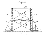
- Fig. 4 also indicates that it is possible to install one or more cross-configurations 20, 21 and/or horizontal tie cables 22 in the section above the horizontal beam 12.
Description
- The invention relates to an artificial island comprising a platform, such as a pontoon and at least three legs for placing the island on the sea bottom and for supporting the platform, said platform and legs being provided with means for moving the legs and platform with respect to each other in vertical direction and for locking the platform on the legs, said legs being rigidly interconnected at a common level between the outer ends of the legs by means of a frame structure, said legs and frame structure being located outside the perimeter of the platform.
- An artificial island of this type is known from US-A 3 402 557. In said known artificial island pontoon and legs are free to move with respect to each other in a vertical direction due to the fact that the legs together with the interconnecting frame structure, lie completely outside the perimeter of the pontoon. In said known structure the legs are not only interconnected by a rigid frame structure halfway the height of the legs but also by a similar rigid frame structure near the top of the legs and close to the lower ends. This means that the legs and interconnecting frame structures form a heavy unit. This unit can be moved to the place of destination by making use of the buoyancy of the pontoon whereafter the entire supporting structure formed by all the legs and interconnecting frame structures can be lowered by using the jacking mechanism. When the supporting structure is placed the pontoon can be moved upwards along the legs up to a level out of reach of the waves.
- During lowering of the supporting structure the pontoon, however, is subjected to the movements of the waves. This means that any movement of the pontoon about the horizontal axis results in a swinging movement of the supporting structure. When the lower end of the supporting structure comes close to the sea bottom this means that the pontoon carries a heavy pendulum swinging over the bottom which pendulum at further lowering of the structure will hit the bottom. This means the sudden occurrence of heavy loads must be taken up by the frame structure without disturbing the connection between the pontoon and the legs. For this purpose the pontoon is guided upon the legs such that the bending moments, which at the connection with the pontoon have a high value, can be taken up.
- Purpose of the invention is to provide an artificial island having a light construction, which island is better suited for great water depths and/ or heavy weather conditions and yet is simple of construction.
- According to the invention said object is achieved in that the supporting joints between each leg and the platform is a pivot joint and at least the leg sections below the rigid frame structure are only interconnected by a cross configuration of cables or ties located outside the perimeter of the platform. This means that the connection between the platform or pontoon and each leg, although made such that leg and platform cannot move apart, does not take up any moment and that the supporting structure preferably is only formed by the legs and the interconnecting rigid structure at half height of the legs, the taking up of moments being performed by the crosswise extending cables or the like extending in planes outside the perimeter of the platform. Said cables form a light construction whereas the connection between platform and legs also allows a light construction. The result is a supporting structure which during lowering is not a heavy but a light pendulum; which surprisingly can be handled well during the dynamic situation occurring during lowering the supporting structure or raising respectively and which in the stationary operative position is capable of taking up occurring toads from wind and waves and from the operations for which the island has been designed.
- It is observed that from published NL-A 7 201 658 an artificial island is known comprising the combination of a supporting frame structure standing upon a pontoon and a buoyant platform. Both components are prefabricated and floated towards the destination where the supporting structure is lowered upon the sea bottom by adding ballast, is embedded in the sea bottom and filled with concrete to obtain a non-removable supporting structure. The lowering of such a structure is different from the lowering of a structure suspended from a pontoon because the pontoon is ballasted and does not act as . a a pendulum.
- The platform is separately floated to the already placed supporting structure and lifted out of the water by means of hoisting devices provided temporarily after which the platform is provided with laterally extending supports or arms which rest upon the supporting structure by means of bearings which act as a pivot point. Due to this way of supporting the platform no moments are transferred towards the supporting structure. The support is the same as usual for supporting a bridge. This manner of supporting the platform is not able to take up horizontal forces or with other words it is not a joint.
- By the combination of rigidly connected horizontal beams and the cross-configuration of the tie beams or cables in the island of the invention, a light construction can be realized. Preferably the horizontal beams are thereby located at the half height of said legs.
- According to the invention it is possible to connect the legs over their whole length to each other. If these connections are hindering the accessibility, e.g. the supply of material, then the connections positioned above the horizontal beams can be embodied removable. Such removable cable connection can also be useful to couple the upper ends of said legs together when said legs are in the raised position.
- The invention makes it possible to alter the horizontal cross-section of each leg in the height or longitudinal direction of said leg. Said cross-section can be adapted to the acting momental load such that the cross-section narrows from the horizontal beams to the ends of the legs. It is also possible to enlarge the cross-section of the part underneath said beams to get an increased standing surface and therewith an increased stability. These possibilities to vary the cross sectional shape, which are only mentioned as examples, are offered because of the pivot joint support of the platform and because the platform is able to move freely in vertical direction through the supporting construction formed by the legs and the connecting means without obstructing said freedom of movement by parts of the supporting construction.
- Because the legs are coupled to each other into a rigid configuration it is not possible as by the known islands to adapt said legs independent of each other in vertical direction and also adaptions to bottom irregularities are not simply possible anymore. One of the measures to avoid inclination and to make adaptions possible is to provide the legs with extendible and retractable jacks or auxiliary legs. These means are individually known from the prior art, just as the possibility to provide the under side of the legs with displacing means, such as endless-track units.
- It is remarked that in "Ocean Industry", September 1973, page 115, an artificial island is described comprising a supporting frame with in vertical direction in relation thereto displaceable supporting legs and rigidly thereto connected upwards directed columns for moving the pontoon there along and arresting said pontoon. In this known construction the moments resulting from horizontal loads are transferred through the columns and the legs with the thereto coupled supporting frame and have a value which is approximately half the value generated in islands having throughgoing columns whereby the coupling between the legs and the pontoon is realized by means of leg guiding elements onto said pontoon. The necessity to use guiding elements for said legs which are able to receive said moments, however, still consists and the supporting frame carrying said columns therefore is still a heavy construction.
- Furthermore known is the "Transworld Rig 60" built by Mitsui Shipbuilding & Engineering Co., Ltd., comprising four vertical buoyancy bodies which are coupled to each other by means of a framework of tubes from which four tubular columns are reaching upwards along which the platform can be moved upwards or downwards. Also in this rig the bending moments in the columns are reduced, but the platform can only move downwards until the upper level of the framework coupled to the buoyancy bodies, so that one has a top heavy construction during transport.
- The invention will now be explained in more detail with reference to the drawings.
- Fig. 1 illustrates a side view of an embodiment of an artificial island according to the invention:
- Fig. 2 illustrates another view of the island shown in Fig. 1;
- Fig. 3 illustrates schematically another embodiment; and
- Fig. 4 illustrates a further embodiment.
- The island illustrated in Fig. 1 comprises three
legs platform 4, embodied as a pontoon, is supported by not in detail illustratedcouplings legs upstanding sections 8 and 9 thereof a jacking and latching mechanism, which is also not illustrated in detail is housed. Such mechanism can be realized by jacking and latching cylinders cooperating with latching beams and working with gear racks or toothed sections or other known means. - Onto this platform several devices can be installed such as a
drilling derrick 10, acrane 11 etc. - According to the invention the legs 1 to 3 are coupled into a stiff configuration by means of the
horizontal beams pontoon 4 and by means of cross-configurated tie beams orcables - The legs 1 to 3 have
extendible leg portions 17 at their bottom ends to make adaptions for instance to an inclined sea bottom possible. - The embodiment of Fig. 3 differs from that illustrated in Fig. 1 in fact only in that the legs have a cross-sectional shape with a maximum dimension at the height of the horizontal-
beams 12 and a cross-sectional dimension which is narrowing in the upwards and downwards leg direction as adaption of the necessary material to the generated maximal momental load. - In the embodiment of Fig. 4 the
legs 1 and 2, which are rigidly coupled by thebeams 12 and thecross-configurations sidewards extending broadenings - Fig. 4 also indicates that it is possible to install one or
more cross-configurations horizontal tie cables 22 in the section above thehorizontal beam 12.
Claims (5)
Applications Claiming Priority (2)
| Application Number | Priority Date | Filing Date | Title |
|---|---|---|---|
| NL8006679A NL8006679A (en) | 1980-12-09 | 1980-12-09 | ARTIFICIAL ISLAND. |
| NL8006679 | 1980-12-09 |
Publications (2)
| Publication Number | Publication Date |
|---|---|
| EP0053861A1 EP0053861A1 (en) | 1982-06-16 |
| EP0053861B1 true EP0053861B1 (en) | 1985-03-20 |
Family
ID=19836301
Family Applications (1)
| Application Number | Title | Priority Date | Filing Date |
|---|---|---|---|
| EP81201329A Expired EP0053861B1 (en) | 1980-12-09 | 1981-12-04 | Artificial island |
Country Status (3)
| Country | Link |
|---|---|
| EP (1) | EP0053861B1 (en) |
| NL (1) | NL8006679A (en) |
| NO (1) | NO151835C (en) |
Families Citing this family (3)
| Publication number | Priority date | Publication date | Assignee | Title |
|---|---|---|---|---|
| NL8501456A (en) * | 1985-05-21 | 1986-12-16 | Rsv Gusto Eng Bv | LIFTING ISLAND. |
| FR2731727B1 (en) * | 1995-03-14 | 1997-06-27 | Solmarine | MARINE PLATFORM WITH STAYS |
| EP3584369A1 (en) * | 2018-06-18 | 2019-12-25 | Vallourec Deutschland GmbH | Device for levelling an offshore foundation construction |
Family Cites Families (6)
| Publication number | Priority date | Publication date | Assignee | Title |
|---|---|---|---|---|
| US2210408A (en) * | 1938-09-08 | 1940-08-06 | Lee C Moore & Company Inc | Marine working platform substructure |
| US3367119A (en) * | 1966-01-20 | 1968-02-06 | Signal Oil & Gas Co | Flotation device for offshore platform assembly |
| US3402557A (en) * | 1966-08-24 | 1968-09-24 | Clayton R. Steele | Supporting structure for offshore drilling rigs |
| GB1220689A (en) * | 1967-12-29 | 1971-01-27 | Nederlandse Offshore Co | Method and apparatus for the construction of an offshore platform |
| GB1380586A (en) * | 1971-02-08 | 1975-01-15 | Redpath Dorman Long North Sea | Structure and a method and apparatus for founding a structure |
| US3727414A (en) * | 1971-06-28 | 1973-04-17 | Bowden Drilling Services Ltd | Off shore drilling platform construction |
-
1980
- 1980-12-09 NL NL8006679A patent/NL8006679A/en not_active Application Discontinuation
-
1981
- 1981-12-04 EP EP81201329A patent/EP0053861B1/en not_active Expired
- 1981-12-08 NO NO814183A patent/NO151835C/en unknown
Also Published As
| Publication number | Publication date |
|---|---|
| NO151835B (en) | 1985-03-04 |
| NO814183L (en) | 1982-06-10 |
| NL8006679A (en) | 1982-07-01 |
| EP0053861A1 (en) | 1982-06-16 |
| NO151835C (en) | 1985-06-12 |
Similar Documents
| Publication | Publication Date | Title |
|---|---|---|
| US4714382A (en) | Method and apparatus for the offshore installation of multi-ton prefabricated deck packages on partially submerged offshore jacket foundations | |
| US4746245A (en) | Offshore drilling and/or production system | |
| US6149350A (en) | Method and apparatus for the offshore installation of multi-ton packages such as deck packages and jackets | |
| US20110305521A1 (en) | Movable brace frame for self-installing platform | |
| EP0906476B1 (en) | A device and method for lifting a sea-going structure, for instance a drilling platform | |
| US8496406B2 (en) | Positioning a sinking tunnel section | |
| GB2174648A (en) | Installation and removal vessel | |
| US5975807A (en) | Method and apparatus for the offshore installation of multi-ton packages such as deck packages and jackets | |
| US4012917A (en) | Bridge beam tower erection methods and apparatus | |
| US4002038A (en) | Method and apparatus for rapid erection of offshore towers | |
| US2598088A (en) | Offshore platform structure and method of erecting same | |
| US3027633A (en) | Method and apparatus for bridge construction | |
| US4739840A (en) | Method and apparatus for protecting a shallow water well | |
| JPS62215711A (en) | Ocean structure and method for anchoring the same | |
| US2612025A (en) | Prefabricated marine structure | |
| KR20100087094A (en) | Method for installing a drilling apparatus on a rig and for preparing drilling operations | |
| EP0475685B1 (en) | Offshore structure | |
| EP0053861B1 (en) | Artificial island | |
| US4653656A (en) | Double center luffing crane | |
| US6648555B2 (en) | Jack-up platform comprising a deck structure and a single supporting column, and method for installing such jack-up platform | |
| US4824291A (en) | Offshore tower structures | |
| US4244663A (en) | Apparatus for restricting pipe motion | |
| US4253780A (en) | Method of positioning a flare support structure for a petroleum platform | |
| USRE35912E (en) | Method of installing lean-to well protector | |
| GB2116615A (en) | Fixed gravity platform of reticular tripod structure |
Legal Events
| Date | Code | Title | Description |
|---|---|---|---|
| PUAI | Public reference made under article 153(3) epc to a published international application that has entered the european phase |
Free format text: ORIGINAL CODE: 0009012 |
|
| AK | Designated contracting states |
Designated state(s): GB NL |
|
| 17P | Request for examination filed |
Effective date: 19821213 |
|
| GRAA | (expected) grant |
Free format text: ORIGINAL CODE: 0009210 |
|
| AK | Designated contracting states |
Designated state(s): GB NL |
|
| PLBI | Opposition filed |
Free format text: ORIGINAL CODE: 0009260 |
|
| 26 | Opposition filed |
Opponent name: L. SCHULER GMBH Effective date: 19850903 |
|
| PLBE | No opposition filed within time limit |
Free format text: ORIGINAL CODE: 0009261 |
|
| STAA | Information on the status of an ep patent application or granted ep patent |
Free format text: STATUS: NO OPPOSITION FILED WITHIN TIME LIMIT |
|
| NLR1 | Nl: opposition has been filed with the epo |
Opponent name: L. SCHULER GMBH |
|
| 26N | No opposition filed | ||
| PGFP | Annual fee paid to national office [announced via postgrant information from national office to epo] |
Ref country code: NL Payment date: 19871231 Year of fee payment: 7 |
|
| PGFP | Annual fee paid to national office [announced via postgrant information from national office to epo] |
Ref country code: GB Payment date: 19890131 Year of fee payment: 8 |
|
| PG25 | Lapsed in a contracting state [announced via postgrant information from national office to epo] |
Ref country code: GB Effective date: 19891204 |
|
| PG25 | Lapsed in a contracting state [announced via postgrant information from national office to epo] |
Ref country code: NL Effective date: 19900701 |
|
| GBPC | Gb: european patent ceased through non-payment of renewal fee | ||
| NLV4 | Nl: lapsed or anulled due to non-payment of the annual fee |