EP0053839B1 - Hand tool for loosening, cutting and crumbling soil - Google Patents
Hand tool for loosening, cutting and crumbling soil Download PDFInfo
- Publication number
- EP0053839B1 EP0053839B1 EP19810110267 EP81110267A EP0053839B1 EP 0053839 B1 EP0053839 B1 EP 0053839B1 EP 19810110267 EP19810110267 EP 19810110267 EP 81110267 A EP81110267 A EP 81110267A EP 0053839 B1 EP0053839 B1 EP 0053839B1
- Authority
- EP
- European Patent Office
- Prior art keywords
- bearing
- sleeves
- hand tool
- tool according
- central
- Prior art date
- Legal status (The legal status is an assumption and is not a legal conclusion. Google has not performed a legal analysis and makes no representation as to the accuracy of the status listed.)
- Expired
Links
Images

Classifications
-
- A—HUMAN NECESSITIES
- A01—AGRICULTURE; FORESTRY; ANIMAL HUSBANDRY; HUNTING; TRAPPING; FISHING
- A01B—SOIL WORKING IN AGRICULTURE OR FORESTRY; PARTS, DETAILS, OR ACCESSORIES OF AGRICULTURAL MACHINES OR IMPLEMENTS, IN GENERAL
- A01B1/00—Hand tools
- A01B1/22—Attaching the blades or the like to handles; Interchangeable or adjustable blades
-
- A—HUMAN NECESSITIES
- A01—AGRICULTURE; FORESTRY; ANIMAL HUSBANDRY; HUNTING; TRAPPING; FISHING
- A01B—SOIL WORKING IN AGRICULTURE OR FORESTRY; PARTS, DETAILS, OR ACCESSORIES OF AGRICULTURAL MACHINES OR IMPLEMENTS, IN GENERAL
- A01B1/00—Hand tools
- A01B1/06—Hoes; Hand cultivators
- A01B1/14—Hoes; Hand cultivators with teeth only
Definitions
- the invention relates to a handheld device for loosening, cutting and crumbling garden soil.
- DE-C-1 303 552 already shows such a hand-held device with freely rotating tine stars arranged on V-shaped bearing axes.
- the radial center planes of these tine stars with a cross-section that is preferably diamond-shaped in cross-section with laterally lying cutting edges on each tine, intersect at an acute angle, so that the mutually sliding edges of the crossed interlocking tines form shear points.
- the object of the invention is to improve these known advantageous hand-held devices, in which 2 tine stars rotate freely on each handle, to the extent that u. a. the risk of corrosion and the number of stalks are reduced and the position of the tine stars and their interchangeability are improved.
- tine stars rotate freely around bearing sleeves, of which at least two spacer sleeves formed from intermediate plastic are kept at a distance, can be rotated together with them and, after release of an end bias, can be displaced in the longitudinal direction are lined up in a straight central axis.
- the bearing sleeves carrying the tine stars are also preferably made of plastic, on which the tine stars with inserted plain bearing rings made of self-forging plastic or the like are freely rotatable.
- bearing sleeves and the spacer sleeves are slidably mounted on the central axis, they can be easily removed from the axis for replacing tine stars or bearing parts and can be opened again. It is preferred according to the invention to clamp the displaceable bearing parts (bearing sleeves, spacer sleeves) against one another by means of clamping nuts screwed on the end side, so that the bearing parts form a rigid unit on the central axis, which is arranged on a stem.
- the overall assembly of such handheld devices can be carried out quickly and easily in terms of production, so that rational production is provided.
- a central axis 11 is fastened, for example welded, which shows an angular cross section.
- bearing sleeves 12 made of hard plastic are pushed in a V-shape to each other, arranged in pairs at corresponding angles (acute angles), between which guide bearings or spacer sleeves 13 are also switched on made of hard plastic, the side faces of which are also V-shaped against one another and over the entire surface rest on the side surfaces of the bearing sleeves 12.
- the side surfaces of the guide bearings 13 have small gradations.
- the central openings 12a of the bearing sleeves 12 and guide bearings 13 and end bearings 14 are also angular, so that these bearing parts 12, 13, 14 can be displaced in the longitudinal direction of the central axis 11, but not on the latter are rotatably mounted.
- the aforementioned bearing parts 12, 13, 14 are clamped together to form a largely rigid unit by means of end nuts 15, which are rotatably mounted on end threads 16 of the central axis 11.
- the outer side surfaces of the end bearings 14 are each at right angles to the end nuts 15.
- the freely rotatable tine stars 17, for example made of light metal such as aluminum, are each diamond-shaped in cross-section and provided with lateral cutting edges 17a and are mounted to one another on the bearing sleeves 12 in such a way that they cross-overlap one another and thereby engage in pairs Form shear points.
- the shear points lie in adjacent tine stars 17 (see FIG. 2) alternately offset.
- each tine star 17 has a central bore 18 into which a slide bearing ring 19, for. B. is made of self-lubricating plastic, which is freely rotatable on the round outer surface (jacket) of the bearing sleeve 12.
- the guide bearings 13 show on their wider outer surface a trough 13b which on the one hand forms a guide surface for grass or the like and on the other hand largely prevents grass or the like from directly wrapping itself in the gaps in the guide bearing 13 and bearing 12; this thus counteracts a setting of the tine stars 17.
- the arrangement of the tine stars 17 with their bearings 12 on the central axis 11 gives the handheld device an advantageous rigidity, especially when working on a hardened soil.
- the individual bearing parts 12, 13, 14 and the tine stars 17 can be easily assembled and loosened again, since the end screws 15 make it easier to put the individual parts on and clamp them together and loosen them.
- the bearing parts are secured against rotation, while the tine stars 17 with the bearing sleeves 12 and slide bearing ring 19 slide plastic on plastic.
- the stem 10 which is preferably made of hard plastic and has a grommet 20, has an elongated flat cavity 21 on the axis side in which a reinforcing plate 22 made of metal is injected, which is provided with central bores 23 for forming a plastic bridge.
- the central axis 11 is rigidly connected to this reinforcing plate 23 by welding at the end face, so that the handle and axis 11 form an inseparable unit.
- the manufacture and assembly of the hand-held device can take place, for example, in such a way that the reinforcing plate 22 is first welded, screwed or the like in the middle of the central axis 11. Then the plastic coating is injection molded to form a V-shaped intermediate guide bearing 10a both around the central axis 11 and around the reinforcing plate, a spout 20 being formed and the liquid plastic flowing through the bores 23 and there bridges 24 for stiffening and expedient Fixing plastic coating and reinforcing plate 22 forms.
- bearing parts bearing sleeves 12 with attached tine stars 17, intermediate guide bearings 13, end bearings 14
- clamping nuts 15 on the threads 16 (cf. FIG. 3).
- the essential parts of the handheld device are largely made of plastic in order to avoid corrosive metal.
- a round axis 25 is provided, which has a groove 26 which extends over its entire length.
- the respective central opening 12a is formed with a web 27 so that the bearing sleeve 12, the guide bearing 13 and the end bearing 14 with the axis 25 are secured against rotation under tongue and groove connection.
- a web, cam or the like can also be arranged on the rotary axis 25, in which case corresponding recesses are then formed in the respective central openings 12a and the parts 12, 13, 14 prevent rotation on the rotary axis 25.
- the outer surface of the bearing sleeve 12 is interrupted by annular collecting channels 28, grooves or the like, in which the sand collects from the friction surface during the rotational movement of the tine stars 17, see FIGS. 5 and 6.
- annular collecting troughs 28 lead into discharge channels 29 arranged at right angles thereto, which are distributed around the circumference of the bearing sleeves 12.
- discharge channels 29 are arranged. The sand or the like accumulated in the collecting troughs 28 is led to the outside via the discharge channels 29.
- a bearing sleeve designed in this way thereby reduces the friction of the rotating tines, which has a favorable effect on the function and the service life.
Landscapes
- Life Sciences & Earth Sciences (AREA)
- Engineering & Computer Science (AREA)
- Mechanical Engineering (AREA)
- Soil Sciences (AREA)
- Environmental Sciences (AREA)
- Health & Medical Sciences (AREA)
- Dentistry (AREA)
- Oral & Maxillofacial Surgery (AREA)
- Soil Working Implements (AREA)
- Handcart (AREA)
Description
Die Erfindung bezieht sich auf ein Handgerät zum Auflockern, Schneiden und Krümeln von Gartenboden.The invention relates to a handheld device for loosening, cutting and crumbling garden soil.
Die DE-C-1 303 552 zeigt bereits ein solches Handgerät mit auf V-förmig zueinanderstehenden Lagerachsen angeordneten freidrehenden Zinkensternen. Die Radialmittelebenen dieser Zinkensterne mit im Querschnitt vorzugsweise rautenförmigen Querschnitt mit seitlich liegenden Schneidkanten an jedem Zinken, schneiden sich unter einem spitzen Winkel, so daß die aneinander entlanggleitenden Kanten der gekreuzt ineinandergreifenden Zinken Scherstellen bilden.DE-C-1 303 552 already shows such a hand-held device with freely rotating tine stars arranged on V-shaped bearing axes. The radial center planes of these tine stars, with a cross-section that is preferably diamond-shaped in cross-section with laterally lying cutting edges on each tine, intersect at an acute angle, so that the mutually sliding edges of the crossed interlocking tines form shear points.
Eine solche Ausbildung zeigt wesentliche Vorteile in bezug auf die Zerkleinerung von Klumpen sowie eine vorteilhafte Selbstreinigung aufgrund des scherenartigen Aufeinanderbewegens.Such training shows significant advantages with regard to the crushing of lumps as well as an advantageous self-cleaning due to the scissors-like movement towards one another.
Aufgabe der Erfindung ist es, diese bekannten vorteilhaften Handgeräte, bei denen an jedem Stiel jeweils 2 Zinkensterne frei sich drehen, noch zu verbessern, und zwar dahingehend, daß u. a. die Korrosionsgefahr und die Zahl der Stiele herabgemindert sowie die Lagerführung der Zinkensterne und deren Auswechselbarkeit verbessertwird.The object of the invention is to improve these known advantageous hand-held devices, in which 2 tine stars rotate freely on each handle, to the extent that u. a. the risk of corrosion and the number of stalks are reduced and the position of the tine stars and their interchangeability are improved.
Diese Aufgabe wird bei einem Handgerät der angegebenen Gattung dadurch gelöst, daß sich die Zinkensterne frei um Lagerhülsen drehen, von denen mindestens zwei, von dazwischenliegenden aus Kunststoff gebildeten Abstandshülsen auf Abstand gehalten, zusammen mit diesen umdrehbar und nach Lösung einer endseitigen Vorspannung in Längsrichtung verschiebbar auf einer geraden zentralen Achse aufgereiht sind.This object is achieved in a hand-held device of the type specified in that the tine stars rotate freely around bearing sleeves, of which at least two spacer sleeves formed from intermediate plastic are kept at a distance, can be rotated together with them and, after release of an end bias, can be displaced in the longitudinal direction are lined up in a straight central axis.
Eine derartige Ausbildung zeigt den Vorteil, daß bei der Anordnung von mehreren Lagerachsenpaaren der Anteil an Metall-Abstandshülsenteilen und damit die Korrosionsgefahr reduziert ist. Diese Vorteile können noch verstärkt werden, wenn erfindungsgemäß vorzugsweise die die Zinkensterne tragenden Lagerhülsen auch aus Kunststoff vorgesehen sind, auf denen die Zinkensterne mit eingesetzten Gleitlagerringen aus selbstschmiedendem Kunststoff od. dgl. frei drehbar lagern.Such a design has the advantage that the arrangement of several pairs of bearing axles reduces the proportion of metal spacer sleeve parts and thus the risk of corrosion. These advantages can be increased if, according to the invention, the bearing sleeves carrying the tine stars are also preferably made of plastic, on which the tine stars with inserted plain bearing rings made of self-forging plastic or the like are freely rotatable.
Dadurch, daß die Lagerhülsen und die Zwischenabstandshülsen auf der zentralen Achse verschiebbar gelagert sind, können sie von der Achse zum Auswechseln von Zinkensternen oder Lagerteilen leicht abgezogen und wieder aufgestreift werden. Dabei ist es erfindungsgemäß bevorzugt, die verschiebbaren Lagerteile (Lagerhülsen, Zwischenabstandshülsen) mittels endseitig angeschraubter Spannmuttern gegeneinander zu verspannen, so daß die Lagerteile auf der zentralen Achse eine starre Einheit bilden, die an einem Stiel angeordnet ist.Characterized in that the bearing sleeves and the spacer sleeves are slidably mounted on the central axis, they can be easily removed from the axis for replacing tine stars or bearing parts and can be opened again. It is preferred according to the invention to clamp the displaceable bearing parts (bearing sleeves, spacer sleeves) against one another by means of clamping nuts screwed on the end side, so that the bearing parts form a rigid unit on the central axis, which is arranged on a stem.
Es ist bevorzugt die äußere Mantelfläche der Lagerhülse mit ringförmigen Sammelrinnen und rechtwinklig dazu angeordnet Abführkanäle unterbrochen auszubilden um das einfallende Gut wie Sand od. dgl. beim Einstechen der Zinkensterne in den Boden nach außen abzuführen.It is preferred to form the outer circumferential surface of the bearing sleeve with annular collecting troughs and discharge channels arranged at right angles thereto in order to discharge the incoming material such as sand or the like to the outside when the tine stars are inserted into the ground.
Die Gesamtmontage derartiger Handgeräte ist fertigungsmäßig schnell und einfach vorzunehmen, so daß eine rationelle Fertigung gegeben ist.The overall assembly of such handheld devices can be carried out quickly and easily in terms of production, so that rational production is provided.
Weitere Merkmale ergeben sich aus den Unteransprüchen.Further features emerge from the subclaims.
Auf der Zeichnung sind Ausführungsbeispiele der Erfindung dargestellt. Es zeigt
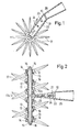
- Fig. 1 eine Seitenansicht eines Handgerätes mit im senkrechten Schnitt dargestelltem Stiel und daran gelagertem Zinkenstern;
- Fig. 2 einen waagerechten Schnitt durch denselben Stiel und mehrere Zinkensternpaare, deren V-förmig zueinander stehende Lager auf einer zentralen Achse angeordnet sind;
- Fig.3 eine Explosionsdarstellung mit Lagern und Zwischenführungslagern mit einer Aufnahmebohrung für die zentrale Achse;
- Fig. 4 einen Querschnitt einer abgeänderten runden Achse und aufgesteckter Lagerhülse mit Nut-Feder Verbindung;
- Fig. 5 eine perspektivische Ansicht einer abgeänderten Lagerhülse mit mantelseitigen Nuten und
- Fig. 6 einen senkrechten Schnitt durch die Lagerhülse nach Fig. 5.
- Figure 1 is a side view of a handheld device with a handle shown in vertical section and tine star mounted thereon.
- Figure 2 is a horizontal section through the same stem and several pairs of tines whose V-shaped bearings are arranged on a central axis.
- 3 shows an exploded view with bearings and intermediate guide bearings with a receiving bore for the central axis;
- Figure 4 shows a cross section of a modified round axis and attached bearing sleeve with tongue and groove connection.
- Fig. 5 is a perspective view of a modified bearing sleeve with shell-side grooves and
- 6 shows a vertical section through the bearing sleeve according to FIG. 5.
An einem Stiel 10 ist eine zentrale Achse 11 befestigt, beispielsweise angeschweißt, die einen eckigen Querschnitt zeigt. Auf diese zentrale Achse sind V-förmig zueinanderstehende, paarweise in korrespondierenden Winkeln (spitzen Winkeln) angeordnete Lagerhülsen 12 aus hartem Kunststoff aufgeschoben, zwischen denen Führungslager oder Abstandshülsen 13 ebenfalls aus hartem Kunststoff eingeschaltet sind, deren Seitenflächen ebenfalls V-förmig sich gegen überliegen und vollflächig an den Seitenflächen der Lagerhülsen 12 anliegen. Dazu haben die Seitenflächen der Führungslager 13 geringe Abstufungen.On a
Entsprechend der eckigen Formgebung der zentralen Achse 11 (quadratisch) sind die Mittelöffnungen 12a der Lagerhülsen 12 und Führungslager 13 sowie Endlager 14 ebenfalls eckig ausgebildet, so daß diese Lagerteile 12, 13, 14 zwar in Längsrichtung der zentralen Achse 11 verschiebbar, jedoch auf dieser nicht drehbar gelagert sind. Durch Endmuttern 15, die auf Endgewinden 16 der zentralen Achse 11 drehbar gelagert sind, sind die vorgenannten Lagerteile 12, 13, 14 miteinander zu einer weitgehend starren Einheit verspannt. Dabei liegen die äußeren Seitenflächen der Endlager 14 rechtwinklig an den Endmuttern 15 jeweils an.According to the angular shape of the central axis 11 (square), the
Die frei drehbaren Zinkensterne 17, beispielsweise aus Leichtmetall wie Aluminium, sind jeweils im Querschnitt rautenförmig und mit seitli chen Schneidkanten 17a versehen und derart zu einander auf den Lagerhülsen 12 gelagert, daß sie aneinandergleitend gekreuzt einseitig ineinandergreifen und dabei paarweise vorteilhafte Scherstellen bilden. Die Scherstellen liegen bei benachbarten Zinkensternen 17 (vergl. Fig. 2) wechselweise versetzt sich gegenüber.The freely rotatable tine stars 17, for example made of light metal such as aluminum, are each diamond-shaped in cross-section and provided with
Dazu hat jeder Zinkenstern 17 eine zentrale Bohrung 18, in die ein Gleitlagerring 19, z. B. aus selbstschmierendem Kunststoff, fest eingesetzt ist, der auf der runden Außenfläche (Mantel) der Lagerhülse 12 frei drehbar lagert.For this purpose each
Die Führungslager 13 zeigen auf ihrer breiteren Außenfläche eine Mulde 13b, die einerseits eine Führungsfläche für Gras od. dgl. bildet und andererseits weitgehend verhindert, daß sich Gras od. dgl. unmittelbar in die Spalte des Führungslagers 13 und Lagers 12 einwickelt; dieses wirkt damit einem Festsetzen der Zinkensterne 17 entgegen.The
Die Anordnung der Zinkensterne 17 mit ihren Lagern 12 auf der zentralen Achse 11 gibt dem Handgerät insbesondere auch bei Bearbeitung eines verhärteten Bodens eine vorteilhafte Starrheit.The arrangement of the tine stars 17 with their
Die einzelnen Lagerteile 12, 13, 14 sowie die Zinkensterne 17 lassen sich einfach montieren und wieder lösen, da die Endschrauben 15 ein Aufstecken und Miteinanderverspannen der Einzelteile und deren Lösen erleichtert. Die Lagerteile sind gegen Verdrehung gesichert, während die Zinkensterne 17 mit den Lagerhülsen 12 und Gleitlagerring 19 Kunststoff auf Kunststoff gleiten.The individual bearing
Der vorzugsweise aus hartem Kunststoff bestehende Stiel 10 mit seiner Tülle 20 weist achsseitig in seiner Längsrichtung einen länglichen flachen Hohlraum 21 auf, in den eine Verstärkungsplatte 22 aus Metall eingespritzt ist, die mit mittleren Bohrungen 23 für eine Kunststoffbrükkenbildung ausgestattet ist. Die zentrale Achse 11 ist mit dieser Verstärkungsplatte 23 durch stirnseitige Verschweißung starr verbunden, so daß Stiel und Achse 11 eine unlösbare Einheit bilden.The
Die Herstellung und Montage des Handgerätes kann beispielsweise so erfolgen, daß zunächst die Verstärkungsplatte 22 in der Mitte der zentralen Achse 11 angeschweißt, angeschraubt od. dgl. wird. Dann wird der Kunststoffüberzug unter Bildung eines im Querschnitt V-förmigen Zwischenführungslagers 10a sowohl um die zentrale Achse 11 als auch um die Verstärkungsptatte gespritzt, wobei eine Tülle 20 gebildet wird und der flüssige Kunststoff durch die Bohrungen 23 fließt und dort Brücken 24 zur Versteifung und zweckmäßigen Festlegung von Kunststoffüberzug und Verstärkungsplatte 22 bildet.The manufacture and assembly of the hand-held device can take place, for example, in such a way that the
Dann werden von einer und der anderen Seite die Lagerteile (Lagerhülsen 12 mit aufgesetzten Zinkensternen 17, Zwischenführungslager 13, Endlager 14) aufgeschoben und endseitig mittels Spannmuttern 15 auf den Gewinden 16 mit- und gegeneinander verspannt (vergl. Fig. 3).Then the bearing parts (bearing
Die wesentlichen Teile des Handgerätes sind weitgehend aus Kunststoff, um korrosionsfähiges Metall zu vermeiden.The essential parts of the handheld device are largely made of plastic in order to avoid corrosive metal.
Es liegt dabei im Rahmen der Erfindung, auch die zentrale Achse 11 und die Zinkensterne 17 aus widerstandsfähigem harten Kunststoff herzustellen.It is within the scope of the invention to also produce the
Bei dem nach Fig. 4 der Zeichnung dargestellten Ausführungsbeispiel ist anstelle der mehrkantigen zentralen Achse 11 eine runde Achse 25 vorgesehen, die eine, über ihre gesamte Länge sich erstreckende, Nut 26 aufweist.In the embodiment shown in FIG. 4 of the drawing, instead of the polygonal
Dabei ist die jeweilige Mittelöffnung 12a mit einem Steg 27 ausgebildet, so daß die Lagerhülse 12, das Führungslager 13 und das Endlager 14 mit der Achse 25 unter Nut-Federverbindung gegen ein Verdrehen gesichert sind.The respective
Auch kann anstelle der Nut 26 auf der Rundachse 25 ein Steg, Nocken od. dgl. angeordnet sein, wobei dann in den jeweiligen Mittelöffnungen 12a entsprechende Ausnehmungen angeformt sind und die Teile 12, 13, 14 auf der Rundachse 25 ein Verdrehen verhindern.Instead of the
Um während der Bearbeitung des Bodens den einfallenden Sand od. dgl. zwischen Gleitring 19 und Lagerhülse 12 herausführen zu können und um damit die Reibung zu verringern, ist die Mantelfläche der Lagerhülse 12 von ringförmigen Sammelrinnen 28, Nuten od. dgl unterbrochen, in denen sich der Sand während der Drehbewegung der Zinkensterne 17 von der Reibungsfläche sammelt, vergl. Fig. 5 und 6.In order to be able to lead out the incident sand or the like between the
Diese ringförmigen Sammelrinnen 28 münden in rechtwinklig dazu angeordneten Abführkanälen 29, welche am Umfang der Lagerhülsen 12 verteilt angeordnet sind. Im Ausführungsbeispiel sind vier Abführkanäle 29 angeordnet. Der in den Sammelrinnen 28 angesammelte Sand od. dgl. wird über die Abführkanäle 29 nach außen geführt.These
Eine derartig ausgebildete Lagerhülse vermindert dadurch die Reibung der sich drehenden Zinken, was sich vorteilhaft auf die Funktion und die Lebensdauer günstig auswirkt.A bearing sleeve designed in this way thereby reduces the friction of the rotating tines, which has a favorable effect on the function and the service life.
Claims (10)
Priority Applications (1)
| Application Number | Priority Date | Filing Date | Title |
|---|---|---|---|
| AT81110267T ATE15851T1 (en) | 1980-12-10 | 1981-12-09 | HAND-HELD TOOL FOR ROOSTERING, CUTTING AND CRUMPLING GARDEN SOIL. |
Applications Claiming Priority (4)
| Application Number | Priority Date | Filing Date | Title |
|---|---|---|---|
| DE19803046436 DE3046436A1 (en) | 1980-12-10 | 1980-12-10 | Manually operated garden cultivator - has rotors with radial blades mounted in bearing bushes with intermediate, non-rotatable, slidable guide bearings |
| DE3046436 | 1980-12-10 | ||
| DE8132020U | 1981-11-03 | ||
| DE19818132020 DE8132020U1 (en) | 1981-11-03 | 1981-11-03 | "HAND DEVICE FOR UNLOCKING, CUTTING AND CUTTING GARDEN GROUND" |
Publications (2)
| Publication Number | Publication Date |
|---|---|
| EP0053839A1 EP0053839A1 (en) | 1982-06-16 |
| EP0053839B1 true EP0053839B1 (en) | 1985-10-02 |
Family
ID=25789622
Family Applications (1)
| Application Number | Title | Priority Date | Filing Date |
|---|---|---|---|
| EP19810110267 Expired EP0053839B1 (en) | 1980-12-10 | 1981-12-09 | Hand tool for loosening, cutting and crumbling soil |
Country Status (2)
| Country | Link |
|---|---|
| EP (1) | EP0053839B1 (en) |
| CA (1) | CA1170891A (en) |
Families Citing this family (1)
| Publication number | Priority date | Publication date | Assignee | Title |
|---|---|---|---|---|
| CA1242348A (en) * | 1984-01-13 | 1988-09-27 | Hans Vom Braucke | Hand tool for loosening soil |
Family Cites Families (4)
| Publication number | Priority date | Publication date | Assignee | Title |
|---|---|---|---|---|
| FR736952A (en) * | 1932-05-11 | 1932-12-05 | Advanced tillage implement | |
| DE7032388U (en) * | 1970-08-31 | 1970-12-03 | Dreyer Heinrich Wilhelm | SOIL TILLING EQUIPMENT. |
| DE7822114U1 (en) * | 1978-07-24 | 1978-11-09 | Edenfeld, Heinz, 4543 Lienen | TILLAGE EQUIPMENT |
| FR2452232A3 (en) * | 1979-03-29 | 1980-10-24 | Gouvy Et Cie | Fixing tang of tool to handle - using tubular metal socket over tang with epoxy! resin filling before securing end of socket over handle |
-
1981
- 1981-12-04 CA CA000391529A patent/CA1170891A/en not_active Expired
- 1981-12-09 EP EP19810110267 patent/EP0053839B1/en not_active Expired
Also Published As
| Publication number | Publication date |
|---|---|
| CA1170891A (en) | 1984-07-17 |
| EP0053839A1 (en) | 1982-06-16 |
Similar Documents
| Publication | Publication Date | Title |
|---|---|---|
| DE3402064C2 (en) | Tillage implement | |
| EP2386196A1 (en) | Agricultural device for compacting soil | |
| DE102008052581A1 (en) | Bearing arrangement for a tine carrier on a reel of a harvester | |
| EP3669637B1 (en) | Agricultural harvester with conveyor drum | |
| DE3410634C2 (en) | Descaling unit for a descaling device | |
| EP0053839B1 (en) | Hand tool for loosening, cutting and crumbling soil | |
| EP0150731A2 (en) | Gardening hand tool for tilling soil | |
| DE3046436C2 (en) | ||
| EP0578051B1 (en) | Toothed packer roller | |
| DE102017105403A1 (en) | Packer roller for tillage | |
| DE102010007959B4 (en) | gardening equipment | |
| DE3335762C2 (en) | ||
| EP2014834B1 (en) | Spinnerdisc for Winterservice-Spreading-Apparatus | |
| DE2835634A1 (en) | Soil cultivation machine | |
| EP0674829B1 (en) | Cam roller | |
| DE4229823C2 (en) | Cultivating roller for tillage | |
| DE2949126A1 (en) | Spacer ring for coaxial tubes - comprises plastics segments assembled to form ring to provide radial spacing between tubes | |
| EP3440921B1 (en) | Carrying finger, rotatable transporting device and driving unit for a rotatable transporting device | |
| DE8132020U1 (en) | "HAND DEVICE FOR UNLOCKING, CUTTING AND CUTTING GARDEN GROUND" | |
| DE19703495A1 (en) | Multi-purpose twin-shafted mixer trough | |
| DE19505345C1 (en) | Cutting drum for underground coal mining | |
| AT301231B (en) | Agricultural tillage implement | |
| DE2849868A1 (en) | TILLAGE MACHINE | |
| DE2337804C3 (en) | Horizontal axis rotor | |
| DE19546615B4 (en) | Star or packer star roller for consolidating agricultural soils and for crushing clods |
Legal Events
| Date | Code | Title | Description |
|---|---|---|---|
| PUAI | Public reference made under article 153(3) epc to a published international application that has entered the european phase |
Free format text: ORIGINAL CODE: 0009012 |
|
| AK | Designated contracting states |
Designated state(s): AT BE CH FR GB IT NL SE |
|
| 17P | Request for examination filed |
Effective date: 19821216 |
|
| ITF | It: translation for a ep patent filed |
Owner name: ING. PIOVESANA PAOLO |
|
| GRAA | (expected) grant |
Free format text: ORIGINAL CODE: 0009210 |
|
| AK | Designated contracting states |
Designated state(s): AT BE CH FR GB IT LI NL SE |
|
| REF | Corresponds to: |
Ref document number: 15851 Country of ref document: AT Date of ref document: 19851015 Kind code of ref document: T |
|
| ET | Fr: translation filed | ||
| PLBE | No opposition filed within time limit |
Free format text: ORIGINAL CODE: 0009261 |
|
| STAA | Information on the status of an ep patent application or granted ep patent |
Free format text: STATUS: NO OPPOSITION FILED WITHIN TIME LIMIT |
|
| 26N | No opposition filed | ||
| ITTA | It: last paid annual fee | ||
| PGFP | Annual fee paid to national office [announced via postgrant information from national office to epo] |
Ref country code: SE Payment date: 19941102 Year of fee payment: 14 Ref country code: GB Payment date: 19941102 Year of fee payment: 14 |
|
| PGFP | Annual fee paid to national office [announced via postgrant information from national office to epo] |
Ref country code: FR Payment date: 19941104 Year of fee payment: 14 |
|
| PGFP | Annual fee paid to national office [announced via postgrant information from national office to epo] |
Ref country code: CH Payment date: 19941125 Year of fee payment: 14 |
|
| PGFP | Annual fee paid to national office [announced via postgrant information from national office to epo] |
Ref country code: BE Payment date: 19941130 Year of fee payment: 14 |
|
| PGFP | Annual fee paid to national office [announced via postgrant information from national office to epo] |
Ref country code: AT Payment date: 19941230 Year of fee payment: 14 |
|
| PGFP | Annual fee paid to national office [announced via postgrant information from national office to epo] |
Ref country code: NL Payment date: 19941231 Year of fee payment: 14 |
|
| EAL | Se: european patent in force in sweden |
Ref document number: 81110267.2 |
|
| PG25 | Lapsed in a contracting state [announced via postgrant information from national office to epo] |
Ref country code: GB Effective date: 19951209 Ref country code: AT Effective date: 19951209 |
|
| PG25 | Lapsed in a contracting state [announced via postgrant information from national office to epo] |
Ref country code: SE Effective date: 19951210 |
|
| PG25 | Lapsed in a contracting state [announced via postgrant information from national office to epo] |
Ref country code: LI Effective date: 19951231 Ref country code: CH Effective date: 19951231 Ref country code: BE Effective date: 19951231 |
|
| BERE | Be: lapsed |
Owner name: BIELEFELDER KUCHENMASCHINEN- UND TRANSPORTGERATEF Effective date: 19951231 |
|
| PG25 | Lapsed in a contracting state [announced via postgrant information from national office to epo] |
Ref country code: NL Effective date: 19960701 |
|
| GBPC | Gb: european patent ceased through non-payment of renewal fee |
Effective date: 19951209 |
|
| REG | Reference to a national code |
Ref country code: CH Ref legal event code: PL |
|
| PG25 | Lapsed in a contracting state [announced via postgrant information from national office to epo] |
Ref country code: FR Effective date: 19960830 |
|
| NLV4 | Nl: lapsed or anulled due to non-payment of the annual fee |
Effective date: 19960701 |
|
| REG | Reference to a national code |
Ref country code: FR Ref legal event code: ST |