EP0053811A1 - Magnetic recording media - Google Patents
Magnetic recording media Download PDFInfo
- Publication number
- EP0053811A1 EP0053811A1 EP81110124A EP81110124A EP0053811A1 EP 0053811 A1 EP0053811 A1 EP 0053811A1 EP 81110124 A EP81110124 A EP 81110124A EP 81110124 A EP81110124 A EP 81110124A EP 0053811 A1 EP0053811 A1 EP 0053811A1
- Authority
- EP
- European Patent Office
- Prior art keywords
- oxygen
- thin
- magnetic recording
- thin magnetic
- layer
- Prior art date
- Legal status (The legal status is an assumption and is not a legal conclusion. Google has not performed a legal analysis and makes no representation as to the accuracy of the status listed.)
- Granted
Links
- QVGXLLKOCUKJST-UHFFFAOYSA-N atomic oxygen Chemical compound [O] QVGXLLKOCUKJST-UHFFFAOYSA-N 0.000 claims abstract description 59
- 229910052760 oxygen Inorganic materials 0.000 claims abstract description 59
- 239000001301 oxygen Substances 0.000 claims abstract description 59
- 239000010410 layer Substances 0.000 claims abstract description 33
- 239000002344 surface layer Substances 0.000 claims abstract description 21
- 239000000758 substrate Substances 0.000 claims abstract description 20
- 229910052759 nickel Inorganic materials 0.000 claims abstract description 14
- 238000000034 method Methods 0.000 claims description 14
- 238000007738 vacuum evaporation Methods 0.000 claims description 11
- 239000000463 material Substances 0.000 claims description 7
- 125000004429 atom Chemical group 0.000 claims description 3
- 229910052751 metal Inorganic materials 0.000 claims description 3
- 239000002184 metal Substances 0.000 claims description 3
- 125000004430 oxygen atom Chemical group O* 0.000 claims description 3
- 150000002739 metals Chemical class 0.000 claims description 2
- 239000010408 film Substances 0.000 description 38
- 239000010409 thin film Substances 0.000 description 22
- 238000009826 distribution Methods 0.000 description 19
- 238000001704 evaporation Methods 0.000 description 15
- 238000000151 deposition Methods 0.000 description 12
- 230000008021 deposition Effects 0.000 description 12
- 230000008020 evaporation Effects 0.000 description 9
- 229910020630 Co Ni Inorganic materials 0.000 description 6
- 229910002440 Co–Ni Inorganic materials 0.000 description 6
- 229910045601 alloy Inorganic materials 0.000 description 6
- 239000000956 alloy Substances 0.000 description 6
- 238000004544 sputter deposition Methods 0.000 description 4
- 238000000682 scanning probe acoustic microscopy Methods 0.000 description 3
- XEEYBQQBJWHFJM-UHFFFAOYSA-N Iron Chemical compound [Fe] XEEYBQQBJWHFJM-UHFFFAOYSA-N 0.000 description 2
- 150000001875 compounds Chemical class 0.000 description 2
- 238000005137 deposition process Methods 0.000 description 2
- 230000005415 magnetization Effects 0.000 description 2
- 238000004519 manufacturing process Methods 0.000 description 2
- 229910018487 Ni—Cr Inorganic materials 0.000 description 1
- 238000010521 absorption reaction Methods 0.000 description 1
- 238000004458 analytical method Methods 0.000 description 1
- 230000005540 biological transmission Effects 0.000 description 1
- 230000000694 effects Effects 0.000 description 1
- 238000002003 electron diffraction Methods 0.000 description 1
- 229910052742 iron Inorganic materials 0.000 description 1
- 239000006247 magnetic powder Substances 0.000 description 1
- 238000007747 plating Methods 0.000 description 1
- -1 polyethylene terephthalate Polymers 0.000 description 1
- 229920000139 polyethylene terephthalate Polymers 0.000 description 1
- 239000005020 polyethylene terephthalate Substances 0.000 description 1
- 239000000843 powder Substances 0.000 description 1
- 238000012827 research and development Methods 0.000 description 1
- 239000000126 substance Substances 0.000 description 1
Images


Classifications
-
- H—ELECTRICITY
- H01—ELECTRIC ELEMENTS
- H01F—MAGNETS; INDUCTANCES; TRANSFORMERS; SELECTION OF MATERIALS FOR THEIR MAGNETIC PROPERTIES
- H01F41/00—Apparatus or processes specially adapted for manufacturing or assembling magnets, inductances or transformers; Apparatus or processes specially adapted for manufacturing materials characterised by their magnetic properties
- H01F41/14—Apparatus or processes specially adapted for manufacturing or assembling magnets, inductances or transformers; Apparatus or processes specially adapted for manufacturing materials characterised by their magnetic properties for applying magnetic films to substrates
- H01F41/20—Apparatus or processes specially adapted for manufacturing or assembling magnets, inductances or transformers; Apparatus or processes specially adapted for manufacturing materials characterised by their magnetic properties for applying magnetic films to substrates by evaporation
-
- G—PHYSICS
- G11—INFORMATION STORAGE
- G11B—INFORMATION STORAGE BASED ON RELATIVE MOVEMENT BETWEEN RECORD CARRIER AND TRANSDUCER
- G11B5/00—Recording by magnetisation or demagnetisation of a record carrier; Reproducing by magnetic means; Record carriers therefor
- G11B5/62—Record carriers characterised by the selection of the material
- G11B5/64—Record carriers characterised by the selection of the material comprising only the magnetic material without bonding agent
- G11B5/66—Record carriers characterised by the selection of the material comprising only the magnetic material without bonding agent the record carriers consisting of several layers
-
- G—PHYSICS
- G11—INFORMATION STORAGE
- G11B—INFORMATION STORAGE BASED ON RELATIVE MOVEMENT BETWEEN RECORD CARRIER AND TRANSDUCER
- G11B5/00—Recording by magnetisation or demagnetisation of a record carrier; Reproducing by magnetic means; Record carriers therefor
- G11B5/62—Record carriers characterised by the selection of the material
- G11B5/72—Protective coatings, e.g. anti-static or antifriction
-
- G—PHYSICS
- G11—INFORMATION STORAGE
- G11B—INFORMATION STORAGE BASED ON RELATIVE MOVEMENT BETWEEN RECORD CARRIER AND TRANSDUCER
- G11B5/00—Recording by magnetisation or demagnetisation of a record carrier; Reproducing by magnetic means; Record carriers therefor
- G11B5/84—Processes or apparatus specially adapted for manufacturing record carriers
- G11B5/851—Coating a support with a magnetic layer by sputtering
-
- H—ELECTRICITY
- H01—ELECTRIC ELEMENTS
- H01F—MAGNETS; INDUCTANCES; TRANSFORMERS; SELECTION OF MATERIALS FOR THEIR MAGNETIC PROPERTIES
- H01F10/00—Thin magnetic films, e.g. of one-domain structure
- H01F10/08—Thin magnetic films, e.g. of one-domain structure characterised by magnetic layers
- H01F10/10—Thin magnetic films, e.g. of one-domain structure characterised by magnetic layers characterised by the composition
- H01F10/18—Thin magnetic films, e.g. of one-domain structure characterised by magnetic layers characterised by the composition being compounds
-
- H—ELECTRICITY
- H01—ELECTRIC ELEMENTS
- H01F—MAGNETS; INDUCTANCES; TRANSFORMERS; SELECTION OF MATERIALS FOR THEIR MAGNETIC PROPERTIES
- H01F10/00—Thin magnetic films, e.g. of one-domain structure
- H01F10/26—Thin magnetic films, e.g. of one-domain structure characterised by the substrate or intermediate layers
- H01F10/265—Magnetic multilayers non exchange-coupled
-
- Y—GENERAL TAGGING OF NEW TECHNOLOGICAL DEVELOPMENTS; GENERAL TAGGING OF CROSS-SECTIONAL TECHNOLOGIES SPANNING OVER SEVERAL SECTIONS OF THE IPC; TECHNICAL SUBJECTS COVERED BY FORMER USPC CROSS-REFERENCE ART COLLECTIONS [XRACs] AND DIGESTS
- Y10—TECHNICAL SUBJECTS COVERED BY FORMER USPC
- Y10S—TECHNICAL SUBJECTS COVERED BY FORMER USPC CROSS-REFERENCE ART COLLECTIONS [XRACs] AND DIGESTS
- Y10S428/00—Stock material or miscellaneous articles
- Y10S428/90—Magnetic feature
-
- Y—GENERAL TAGGING OF NEW TECHNOLOGICAL DEVELOPMENTS; GENERAL TAGGING OF CROSS-SECTIONAL TECHNOLOGIES SPANNING OVER SEVERAL SECTIONS OF THE IPC; TECHNICAL SUBJECTS COVERED BY FORMER USPC CROSS-REFERENCE ART COLLECTIONS [XRACs] AND DIGESTS
- Y10—TECHNICAL SUBJECTS COVERED BY FORMER USPC
- Y10S—TECHNICAL SUBJECTS COVERED BY FORMER USPC CROSS-REFERENCE ART COLLECTIONS [XRACs] AND DIGESTS
- Y10S428/00—Stock material or miscellaneous articles
- Y10S428/922—Static electricity metal bleed-off metallic stock
- Y10S428/9265—Special properties
- Y10S428/928—Magnetic property
-
- Y—GENERAL TAGGING OF NEW TECHNOLOGICAL DEVELOPMENTS; GENERAL TAGGING OF CROSS-SECTIONAL TECHNOLOGIES SPANNING OVER SEVERAL SECTIONS OF THE IPC; TECHNICAL SUBJECTS COVERED BY FORMER USPC CROSS-REFERENCE ART COLLECTIONS [XRACs] AND DIGESTS
- Y10—TECHNICAL SUBJECTS COVERED BY FORMER USPC
- Y10T—TECHNICAL SUBJECTS COVERED BY FORMER US CLASSIFICATION
- Y10T428/00—Stock material or miscellaneous articles
- Y10T428/12—All metal or with adjacent metals
- Y10T428/12493—Composite; i.e., plural, adjacent, spatially distinct metal components [e.g., layers, joint, etc.]
- Y10T428/12535—Composite; i.e., plural, adjacent, spatially distinct metal components [e.g., layers, joint, etc.] with additional, spatially distinct nonmetal component
- Y10T428/12583—Component contains compound of adjacent metal
- Y10T428/1259—Oxide
-
- Y—GENERAL TAGGING OF NEW TECHNOLOGICAL DEVELOPMENTS; GENERAL TAGGING OF CROSS-SECTIONAL TECHNOLOGIES SPANNING OVER SEVERAL SECTIONS OF THE IPC; TECHNICAL SUBJECTS COVERED BY FORMER USPC CROSS-REFERENCE ART COLLECTIONS [XRACs] AND DIGESTS
- Y10—TECHNICAL SUBJECTS COVERED BY FORMER USPC
- Y10T—TECHNICAL SUBJECTS COVERED BY FORMER US CLASSIFICATION
- Y10T428/00—Stock material or miscellaneous articles
- Y10T428/12—All metal or with adjacent metals
- Y10T428/12493—Composite; i.e., plural, adjacent, spatially distinct metal components [e.g., layers, joint, etc.]
- Y10T428/12639—Adjacent, identical composition, components
- Y10T428/12646—Group VIII or IB metal-base
-
- Y—GENERAL TAGGING OF NEW TECHNOLOGICAL DEVELOPMENTS; GENERAL TAGGING OF CROSS-SECTIONAL TECHNOLOGIES SPANNING OVER SEVERAL SECTIONS OF THE IPC; TECHNICAL SUBJECTS COVERED BY FORMER USPC CROSS-REFERENCE ART COLLECTIONS [XRACs] AND DIGESTS
- Y10—TECHNICAL SUBJECTS COVERED BY FORMER USPC
- Y10T—TECHNICAL SUBJECTS COVERED BY FORMER US CLASSIFICATION
- Y10T428/00—Stock material or miscellaneous articles
- Y10T428/12—All metal or with adjacent metals
- Y10T428/12493—Composite; i.e., plural, adjacent, spatially distinct metal components [e.g., layers, joint, etc.]
- Y10T428/1266—O, S, or organic compound in metal component
Definitions
- the present invention relates to thin-film type magnetic recording media of excellent short wavelength or high-frequency recording characteristics.
- Thin-film type magnetic media can be fabricated by the vacuum evaporation, sputtering or electro- or chemical plating process and exhibit excellent short wavelength or high-frequency information recording capability.
- thin magnetic films consist of Co; Co and Ni; Co and Cr; Co, Ni and Cr; Co and P; or Co, Ni and P.
- the sputtering process is not adapted for the mass production because of slow sputtering or deposition rates. Furthermore, the thin magnetic film deposited by the sputtering process is not stable in maintaining its characteristics. On the other hand, the evaporation or deposition rate of the vacuum evaporation process is very fast and of the order of thousands angstroms per second. In addition, stable thin magnetic films of high coercive force can be easily obtained when the supporting substrate is inclined at an angle to the incident beam of evaporating material.
- the primary object of the present invention is, therefore, to provide a magnetic recording medium which can be easily mass-produced and which has a thin magnetic film which in turn is formed by the deposition mainly of Co; Co and Ni; Co and Cr; or Co, Ni and Cr by the vacuum evaporation process or the like over a supporting substrate made of nonmagnetic material and which has the oxygen contents higher in a surface layer than a deeper layer below it so that the magnetic recording medium has a higher coercive force and exhibits excellent short wavelength or high-frequency information recording capability.
- the thin magnetic film embodying the present invention is featured in that it comprises a surface layer adjacent to the native oxidized layer at surface and a deep layer .below it; and the average oxygen contents are higher in the surface layer than in the deep layer.
- Fig. 1 shows schematically a continuous vacuum evaporation apparatus for the continuous fabrication of a long length of magnetic recording medium.
- a tape-like substrate 1 which is made of a high-molecular compound, is transported along a cylindrical can 2 in the direction indicated by an arrow A. Therefore, the angle of incidence of the vapor beam of evaporating material 6 upon the surface of the substrate 1 continuously varies from the tangential to normal direction as indicated by arrows B.
- a mask 3 controls the angle of incidence of the vapor beam on a magnetic layer (this angle will be referred to as "the minimum incidence angle e" in this specification).
- Reference numeral 4 designates a supply roll; 5, a take-up roll; and 7, a heater for evaporating the evaporating material 6.
- the amount of the oxygen present strongly influences the magnetic characteristics of deposited thin magnetic films as is well known in the art.
- the H c - ⁇ characteristic curve as indicated by 9 in Fig. 2 is obtained when a thin magnetic film is deposited by the evaporation of a Co-Ni alloy (containing 20% by weight of Ni) at the evaporation rate of about 2000 A/sec and in the atmosphere in which the partial pressure of the oxygen is 6 x 10 -4 torr (the oxygen is substantially uniformly distributed in the process chamber). It is apparent that when thin magnetic films are deposited in the oxygen atmosphere, a high coercive force H c can be obtained. As a consequence, a high output signal can be obtained in the reproduction.
- Fig. 3 shows the characteristic curve 10 showing the relationship between the coercive force H and the partial pressure in torr of the oxygen in the evaporation atmosphere when the minimum incidence angle e is 45°. It is seen that with increase in the oxygen partial pressure, the coercive force H increases.
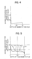
- Fig. 4 shows the oxygen distribution in the direction of thickness of a thin magnetic film deposited in the oxygen atmosphere.
- the contents of oxygen are plotted along the ordinate while the depth of the thin magnetic film, along the abscissa.
- Depth 0 indicates the surface of the thin film and 1.0, the interface between the thin magnetic film and the substrate.
- the oxygen distribution can be measured by Auger electron spectroscopy.
- the angle of vapor incidence is greater at or in the proximity of the interface between the thin film and the substrate.
- the distance between the substrate and the evaporant source is long.
- the deposition or evaporation rate becomes low so that the contents of the oxygen in the thin film are slightly higher in the proximity of the interface between the thin film and the substrate than in the proximity of the surface of the thin film.
- Analyses by Auger electron spectroscopy and transmission electron diffraction showed that the oxygen is present in the thin films in the form of oxides of metals. From Fig. 4.it is seen that a layer at about 10 A is depth from the surface of the thin film has high oxygen contents. This native oxidized layer at surface is formed by the absorption of the oxygen after the deposited thin film is discharged out of the process chamber into the atmosphere.
- magnetic recording media of excellent characteristics can be fabricated by the oblique incidence vacuum evaporation process and their characteristics can be further improved when thin magnetic films are deposited in the oxygen atmosphere.
- high productivity as well as further improvements of their characteristics are desired.
- a coercive force H c at least higher than 800 Oe is needed.
- the minimum incidence angle a must be greater than 60° as described previously with reference to the characteristic curve 9 shown in Fig. 2.
- the minimum incidence angle e is increased in excess of 60°, the deposition rate extremely drops and consequently productivity drops. Therefore, it is preferable to maintain the minimum incidence angle ⁇ less than 50°.
- the oxygen content distributions in the direction of thickness of deposited thin magnetic films can be divided into three types depending upon the partial pressure distribution of the oxygen in the chamber.
- a thin magnetic film is assumed to be comprising a surface adjacent to the native oxidized layer at surface, an intermediate layer and a back surface layer adjacent to the interface between the thin film and the substrate.
- a first oxygen content distribution type is such that the average oxygen content in the surface layer is higher than that in the deep layer as indicated by a curve 11 in Fig. 5.
- a second type is such that the content in the intermediate layer is higher than the average content in the surface and back surface layers as indicated by a curve 12 in Fig. 5.
- a third type is such that the average oxygen content in the back surface layer is higher than the average content in the surface and intermediate layers as indicated by a curve 13 in Fig. 5.
- a thin magnetic film with the first oxygen content distribution type (curve 11) can be deposited in the atmosphere in which the partial pressure of the oxygen is higher adjacent to the mask 3 in the apparatus as shown in Fig. 1 than in the remaining portion.
- the coercive force.H c is low and subsequently the high-frequency recording and reproducing characteristics are degraded.
- the oxygen contents must be distributed as indicated by the curve 11 in Fig. 5.
- the coercive force H c is remarkably lower than that of the thin films embodying the present invention. That is, according to the present invention, thin magnetic films with the coercive force of higher than 800 Oe can be obtained at the minimum incidence angle of 45°, but according to the prior art process, the coercive force of higher than 800 Oe cannot be obtained at the minimum incidence angle of 45°.
- the thin magnetic film with the oxygen content distribution as indicated by the curve 18 is superior to the thin magnetic film with the oxygen content distribution type as indicated by the curve 19..
- the surface layer has a thickness equal to one third of the thickness of a thin magnetic film.
- the curve 18 shows that the average content of the oxygen is higher in the surface layer than in the deep layer and the curve 19 shows that the average oxygen content is higher in the deep layer than in the surface layer.
- the average oxygen content in the surface layer is in excess of 1.2 times as high as that in the deep layer and that the number of oxygen atoms in the thin film is higher by 25% than the number of metal atoms.
- the present invention has been described in conjunction with the deposition of only one thin magnetic film over a nonmagnetic substrate, but it is to be understood that the present invention can be equally applied to the depositions of multi-layer thin magnetic films.
- three layers 20 may be overlaid over the substrate 1, each of the layers 20 having the oxygen content distribution as indicated by the curve 11 in Fig. 5.
- the overall oxygen content distribution in the magnetic layer (that is, the thin film comprising three layers 20) is shown in Fig. 9.
- a Co-Ni alloy (containing 20% by weight of Ni) is deposited to the thickness of 1200 o A at the minimum incidence angle e of 40° over a substrate made of polyethylene terephthalate.
- the average deposition 0 rate is 2500 A/sec and the evaporation atmosphere is so controlled that the partial pressure of the oxygen is higher in the vicinity of the mask 3 than in other portions.
- the . oxygen content distribution in the deposited thin film is measured by Auger electron spectroscopy. The result is similar to the curve or profile 18 shown in Fig. 7.
- the number of oxygen atoms in the thin film is about 35% of the total number of Co and Ni atoms.
- the magnetic characteristics are measured by the vibrating sample magnetometer and the results are that the coercive force H c is 820 Oe; the saturation magnetization M s is 530 emu/cc; and the squareness ratio is 0.88.
- the sinusoidal waveform of the wavelength of 0.8 pm is recorded on the recording media thus obtained and reproduced, the output is higher than 14 dB as compared with a magnetic tape for VTR of the coated type in which a powder of oxide iron containing Co is coated over a substrate.
- magnetic recording media of high coercive force and excellent high-frequency (short wavelength) recording and reproducing characteristics can be fabricated with a higher degree of productivity.
Abstract
Description
- The present invention relates to thin-film type magnetic recording media of excellent short wavelength or high-frequency recording characteristics.
- There has been an increasing tendency for magnetic recording and reproducing apparatus toward recording and reproducing information at higher and higher densities, so that there has been a strong demand for magnetic recording media of excellent short wavelength or high-frequency information recording capability. Conventional magnetic recording media are fabricated in general by applying magnetic powder over a substrate made of high-molecular compounds or nonmagnetic material (and will be referred to as "the coated type" hereinafter in this specification): In order to improve their short wavelength or high-frequency information recording capability, their coercive force and saturation magnetization must be increased, and the magnetic film or layer must be reduced in thickness. However, there are limits to the improvement of the conventional "coated type" magnetic recording medium for better short wavelength or high-frequency information capability, so that a great deal of research-and-development work has been made in order to fabricate thin-film type magnetic recording media. Thin-film type magnetic media can be fabricated by the vacuum evaporation, sputtering or electro- or chemical plating process and exhibit excellent short wavelength or high-frequency information recording capability. In general, thin magnetic films consist of Co; Co and Ni; Co and Cr; Co, Ni and Cr; Co and P; or Co, Ni and P.
- Of the above-described three deposition processes, the sputtering process is not adapted for the mass production because of slow sputtering or deposition rates. Furthermore, the thin magnetic film deposited by the sputtering process is not stable in maintaining its characteristics. On the other hand, the evaporation or deposition rate of the vacuum evaporation process is very fast and of the order of thousands angstroms per second. In addition, stable thin magnetic films of high coercive force can be easily obtained when the supporting substrate is inclined at an angle to the incident beam of evaporating material. In this case, it is well known that the higher the oxygen content in the deposited thin film, the higher the coercive force H becomes and that the larger the angle of vapor incidence, the higher the contents of oxygen in the deposited thin film becomes. However, the increase in the angle of vapor incidence results in remarkable decrease in the deposition rate.
- The primary object of the present invention is, therefore, to provide a magnetic recording medium which can be easily mass-produced and which has a thin magnetic film which in turn is formed by the deposition mainly of Co; Co and Ni; Co and Cr; or Co, Ni and Cr by the vacuum evaporation process or the like over a supporting substrate made of nonmagnetic material and which has the oxygen contents higher in a surface layer than a deeper layer below it so that the magnetic recording medium has a higher coercive force and exhibits excellent short wavelength or high-frequency information recording capability.
- The thin magnetic film embodying the present invention is featured in that it comprises a surface layer adjacent to the native oxidized layer at surface and a deep layer .below it; and the average oxygen contents are higher in the surface layer than in the deep layer.
-
- Fig. 1 is a schematic view used to explain an oblique incidence vacuum evaporation process;
- Fig. 2 is a graph showing the relationship between the coercive force H and the minimum incidence angle e;
- Fig. 3 is a graph showing the relationship between the partial pressure of the oxygen in the evaporation atmosphere and the resulting coercive force H c of deposited thin magnetic films;
- Fig. 4 shows the distribution of oxygen contents in the direction of thickness of a deposited thin magnetic film;
- Fig. 5 shows various types of oxygen content distributions in the direction of thickness of deposited thin magnetic films;
- Fig. 6 is a graph showing the relationships between the coercive force and average oxygen contents in deposited magnetic thin films;
- Fig. 7 shows the oxygen contents distributions in the direction of thickness of thin magnetic films;
- Fig. 8 shows a multi-layer thin magnetic film embodying the present invention; and
- Fig. 9 is a graph showing the oxygen contents distribution in the direction of thickness of the magnetic thin film shown in Fig. 8.
- Fig. 1 shows schematically a continuous vacuum evaporation apparatus for the continuous fabrication of a long length of magnetic recording medium. A tape-like substrate 1, which is made of a high-molecular compound, is transported along a
cylindrical can 2 in the direction indicated by an arrow A. Therefore, the angle of incidence of the vapor beam of evaporatingmaterial 6 upon the surface of the substrate 1 continuously varies from the tangential to normal direction as indicated by arrowsB. A mask 3 controls the angle of incidence of the vapor beam on a magnetic layer (this angle will be referred to as "the minimum incidence angle e" in this specification). Reference numeral 4 designates a supply roll; 5, a take-up roll; and 7, a heater for evaporating the evaporatingmaterial 6. - When Co or an alloy of Co and Ni; Co and Cr; or Co, Ni and Cr is evaporated by the apparatus as shown in Fig. 1, magnetic films or layers of excellent characteristics can be obtained. For instance, when a Co-Ni alloy (containing 20% by weight of Ni) magnetic film is deposited in the vacuum of 3 x 10⁻⁵ torr and at the evaporation rate of 2000 A/sec, the Hc-e characteristic curve as shown by a
curve 8 in Fig. 2 is obtained, where H c is the coercive force in the direction of transport of the substrate 1 when the evaporating material is deposited. It is seen that when the minimum incidence angle e is greater than 60°, the coercive force H c becomes higher than 500 Oe. - When the evaporations are carried out in the atmosphere of the oxygen, the amount of the oxygen present strongly influences the magnetic characteristics of deposited thin magnetic films as is well known in the art.
- The Hc-θ characteristic curve as indicated by 9 in Fig. 2 is obtained when a thin magnetic film is deposited by the evaporation of a Co-Ni alloy (containing 20% by weight of Ni) at the evaporation rate of about 2000 A/sec and in the atmosphere in which the partial pressure of the oxygen is 6 x 10⁻⁴ torr (the oxygen is substantially uniformly distributed in the process chamber). It is apparent that when thin magnetic films are deposited in the oxygen atmosphere, a high coercive force Hc can be obtained. As a consequence, a high output signal can be obtained in the reproduction.
- Fig. 3 shows the
characteristic curve 10 showing the relationship between the coercive force H and the partial pressure in torr of the oxygen in the evaporation atmosphere when the minimum incidence angle e is 45°. It is seen that with increase in the oxygen partial pressure, the coercive force H increases. c - Fig. 4 shows the oxygen distribution in the direction of thickness of a thin magnetic film deposited in the oxygen atmosphere. The contents of oxygen are plotted along the ordinate while the depth of the thin magnetic film, along the abscissa.
Depth 0 indicates the surface of the thin film and 1.0, the interface between the thin magnetic film and the substrate. The oxygen distribution can be measured by Auger electron spectroscopy. - When the apparatus as shown in Fig. 1 is used, the angle of vapor incidence is greater at or in the proximity of the interface between the thin film and the substrate. In addition, the distance between the substrate and the evaporant source is long. As a result, the deposition or evaporation rate becomes low so that the contents of the oxygen in the thin film are slightly higher in the proximity of the interface between the thin film and the substrate than in the proximity of the surface of the thin film. Analyses by Auger electron spectroscopy and transmission electron diffraction showed that the oxygen is present in the thin films in the form of oxides of metals. From Fig. 4.it is seen that a layer at about 10 A is depth from the surface of the thin film has high oxygen contents. This native oxidized layer at surface is formed by the absorption of the oxygen after the deposited thin film is discharged out of the process chamber into the atmosphere.
- As described above, magnetic recording media of excellent characteristics can be fabricated by the oblique incidence vacuum evaporation process and their characteristics can be further improved when thin magnetic films are deposited in the oxygen atmosphere. However, high productivity as well as further improvements of their characteristics are desired. For instance, in order to obtain satisfactory recording and reproduction characteristics in a sub-micron wavelength signal region, a coercive force H c at least higher than 800 Oe is needed. With the prior art process, the minimum incidence angle a must be greater than 60° as described previously with reference to the characteristic curve 9 shown in Fig. 2. However, if the minimum incidence angle e is increased in excess of 60°, the deposition rate extremely drops and consequently productivity drops. Therefore, it is preferable to maintain the minimum incidence angle θ less than 50°.
- In the case of the deposition of thin magnetic films on nonmagnetic substrates by the vacuum evaporation process by evaporating Co; Co and Ni; Co and Cr; or Co, Ni and Cr in the atmosphere containing the oxygen, the oxygen content distributions in the direction of thickness of deposited thin magnetic films can be divided into three types depending upon the partial pressure distribution of the oxygen in the chamber. For the sake of explanation, a thin magnetic film is assumed to be comprising a surface adjacent to the native oxidized layer at surface, an intermediate layer and a back surface layer adjacent to the interface between the thin film and the substrate.
- The combination of the intermediate and back surface layers is called as the deep layer. Then, a first oxygen content distribution type is such that the average oxygen content in the surface layer is higher than that in the deep layer as indicated by a curve 11 in Fig. 5. A second type is such that the content in the intermediate layer is higher than the average content in the surface and back surface layers as indicated by a curve 12 in Fig. 5. A third type is such that the average oxygen content in the back surface layer is higher than the average content in the surface and intermediate layers as indicated by a
curve 13 in Fig. 5. - For instance, a thin magnetic film with the first oxygen content distribution type (curve 11) can be deposited in the atmosphere in which the partial pressure of the oxygen is higher adjacent to the
mask 3 in the apparatus as shown in Fig. 1 than in the remaining portion. - With the vacuum evaporation apparatus as shown in Fig. 1, Co-Ni thin magnetic films (containing 20% by weight of Ni) with three oxygen content distribution types as described above were prepared. The minimum incidence angle e was maintained at 45° and the coercive force H in the direction of transport of the substrate during the deposition process was measured. The results were shown in Fig. 6 in which the coercive force H is plotted along the ordinate while the average contents of the oxygen in the deposited thin films are plotted along the abscissa.
Curves curves 11, 12 and 13, respectively, shown in Fig. 5. In the case of the thin magnetic films with the first oxygen content distribution type (the curve 11 in Fig. 5), the higher the average oxygen content in the thin magnetic film, the higher the coercive force H becomes and subsequently the more excellent the high-frequency (short wavelength) recording and reproducing characteristics become. However, in the case of the thin magnetic film with the third oxygen content distribution type (thecurve 13 in Fig. 5), the coercive force.Hc is low and subsequently the high-frequency recording and reproducing characteristics are degraded. Thus, it is apparent that in order to attain optimum high-frequency recording and reproducing characteristics, the oxygen contents must be distributed as indicated by the curve 11 in Fig. 5. When a thin magnetic film is deposited in the atmosphere in which the partial pressure of the oxygen is uniformly distributed, the characteristic as indicated by acurve 17 in Fig. 6 is obtained. It is seen that the coercive force Hc is remarkably lower than that of the thin films embodying the present invention. That is, according to the present invention, thin magnetic films with the coercive force of higher than 800 Oe can be obtained at the minimum incidence angle of 45°, but according to the prior art process, the coercive force of higher than 800 Oe cannot be obtained at the minimum incidence angle of 45°. - So far, the present invention has been described in conjunction with the deposition of a Co-Ni alloy (containing 20% by weight of Ni), but similar effects and characteristics were also obtained in the cases of depositions of Co-Ni; Co-Cr; and Co-Ni-Cr alloys and Co alone.
- In the case of the first type oxygen content distribution; that is, when the average oxygen content is higher in the surface layer than in the deep layer, two subtypes can be considered as indicated by
curves curve 18 is superior to the thin magnetic film with the oxygen content distribution type as indicated by thecurve 19.. - It is assumed that the surface layer has a thickness equal to one third of the thickness of a thin magnetic film. Then the
curve 18 shows that the average content of the oxygen is higher in the surface layer than in the deep layer and thecurve 19 shows that the average oxygen content is higher in the deep layer than in the surface layer. This means that recording media of excellent characteristics can be fabricated by making the average oxygen content higher in the surface layer, whose thickness is equal to one third of the total thickness of a thin magnetic film, than in the deep or remaining layer. In order to obtain thin magnetic films with higher coercive forces H , it is preferable that the average oxygen content in the surface layer is in excess of 1.2 times as high as that in the deep layer and that the number of oxygen atoms in the thin film is higher by 25% than the number of metal atoms. - So far, the present invention has been described in conjunction with the deposition of only one thin magnetic film over a nonmagnetic substrate, but it is to be understood that the present invention can be equally applied to the depositions of multi-layer thin magnetic films.
- For instance, as shown in Fig. 8, three layers 20 may be overlaid over the substrate 1, each of the layers 20 having the oxygen content distribution as indicated by the curve 11 in Fig. 5. The overall oxygen content distribution in the magnetic layer (that is, the thin film comprising three layers 20) is shown in Fig. 9.
- Next, a more specific embodiment of the present invention will be described. With the vacuum evaporation apparatus as shown in Fig. 1, a Co-Ni alloy (containing 20% by weight of Ni) is deposited to the thickness of 1200 o A at the minimum incidence angle e of 40° over a substrate made of polyethylene terephthalate. The
average deposition 0 rate is 2500 A/sec and the evaporation atmosphere is so controlled that the partial pressure of the oxygen is higher in the vicinity of themask 3 than in other portions. The . oxygen content distribution in the deposited thin film is measured by Auger electron spectroscopy. The result is similar to the curve orprofile 18 shown in Fig. 7. The number of oxygen atoms in the thin film is about 35% of the total number of Co and Ni atoms. The magnetic characteristics are measured by the vibrating sample magnetometer and the results are that the coercive force H c is 820 Oe; the saturation magnetization M s is 530 emu/cc; and the squareness ratio is 0.88. When the sinusoidal waveform of the wavelength of 0.8 pm is recorded on the recording media thus obtained and reproduced, the output is higher than 14 dB as compared with a magnetic tape for VTR of the coated type in which a powder of oxide iron containing Co is coated over a substrate. - In summary, according to the present invention, magnetic recording media of high coercive force and excellent high-frequency (short wavelength) recording and reproducing characteristics can be fabricated with a higher degree of productivity.
Claims (7)
Applications Claiming Priority (2)
| Application Number | Priority Date | Filing Date | Title |
|---|---|---|---|
| JP55172389A JPS5798133A (en) | 1980-12-05 | 1980-12-05 | Magnetic recording medium |
| JP172389/80 | 1980-12-05 |
Publications (2)
| Publication Number | Publication Date |
|---|---|
| EP0053811A1 true EP0053811A1 (en) | 1982-06-16 |
| EP0053811B1 EP0053811B1 (en) | 1985-10-02 |
Family
ID=15941014
Family Applications (1)
| Application Number | Title | Priority Date | Filing Date |
|---|---|---|---|
| EP81110124A Expired EP0053811B1 (en) | 1980-12-05 | 1981-12-03 | Magnetic recording media |
Country Status (4)
| Country | Link |
|---|---|
| US (1) | US4385098A (en) |
| EP (1) | EP0053811B1 (en) |
| JP (1) | JPS5798133A (en) |
| DE (1) | DE3172556D1 (en) |
Cited By (15)
| Publication number | Priority date | Publication date | Assignee | Title |
|---|---|---|---|---|
| EP0066146A2 (en) * | 1981-05-15 | 1982-12-08 | Matsushita Electric Industrial Co., Ltd. | Method for manufacturing magnetic recording medium |
| FR2531797A1 (en) * | 1982-08-12 | 1984-02-17 | Sony Corp | MAGNETIC RECORDING MEDIUM HAVING A THIN FILM IN A FERROMAGNETIC METAL ON A NON-MAGNETIC MEDIUM |
| FR2558631A1 (en) * | 1984-01-20 | 1985-07-26 | Sony Corp | MAGNETIC RECORDING MEDIUM |
| FR2558632A1 (en) * | 1984-01-20 | 1985-07-26 | Sony Corp | MAGNETIC RECORDING MEDIUM |
| DE3503309A1 (en) * | 1984-02-02 | 1985-08-08 | Victor Company Of Japan, Ltd., Yokohama, Kanagawa | MAGNETIC RECORDING MEDIUM WITH A MAGNETIC LAYER DEPOSED IN A VACUUM FROM A MAGNETIZABLE MATERIAL AND A TUNGSTEN MIXTURE AND METHOD FOR PRODUCING THE MEDIUM |
| EP0154158A1 (en) * | 1984-02-02 | 1985-09-11 | Hitachi Metals, Ltd. | Process for manufacturing magnetic recording media |
| EP0182367A2 (en) * | 1984-11-20 | 1986-05-28 | Hitachi Maxell Ltd. | Magnetic recording medium and production of the same |
| EP0198472A2 (en) * | 1985-04-15 | 1986-10-22 | Hitachi Maxell Ltd. | Magnetic recording medium and method for producing the same |
| GB2186293A (en) * | 1986-02-11 | 1987-08-12 | Emi Plc Thorn | Magnetic thin film recording media |
| EP0241155A1 (en) * | 1986-03-31 | 1987-10-14 | Unisys Corporation | Depositing vanadium underlayer for magnetic films |
| US4741967A (en) * | 1983-06-08 | 1988-05-03 | Canon Kabushiki Kaisha | Magnetic recording medium |
| EP0399848A2 (en) * | 1989-05-25 | 1990-11-28 | Hitachi Maxell Ltd. | Magnetic recording medium and method of manufacturing the same |
| US5076203A (en) * | 1987-10-07 | 1991-12-31 | Thorn Emi Plc | Coating apparatus for thin plastics webs |
| EP0329116B1 (en) * | 1988-02-17 | 1994-05-04 | Matsushita Electric Industrial Co., Ltd. | Method for manufacturing perpendicular magnetic recording medium |
| EP0597480A1 (en) * | 1992-11-12 | 1994-05-18 | Matsushita Electric Industrial Co., Ltd. | Magnetic recording medium and method for producing the same |
Families Citing this family (28)
| Publication number | Priority date | Publication date | Assignee | Title |
|---|---|---|---|---|
| JPS5975427A (en) * | 1982-10-21 | 1984-04-28 | Fuji Photo Film Co Ltd | Magnetic recording medium |
| JPS59119531A (en) * | 1982-12-25 | 1984-07-10 | Tdk Corp | Magnetic recording medium |
| JPS59119532A (en) * | 1982-12-25 | 1984-07-10 | Tdk Corp | Magnetic recording medium |
| JPS59119534A (en) * | 1982-12-26 | 1984-07-10 | Tdk Corp | Magnetic recording medium |
| JPS59185024A (en) * | 1983-04-04 | 1984-10-20 | Matsushita Electric Ind Co Ltd | Magnetic recording medium |
| JPS60157717A (en) * | 1984-01-26 | 1985-08-19 | Hitachi Maxell Ltd | Magnetic recording medium |
| JPH0766507B2 (en) * | 1984-02-16 | 1995-07-19 | コニカ株式会社 | Magnetic recording medium |
| KR890004257B1 (en) * | 1984-10-29 | 1989-10-28 | 니뽕 빅터 가부시끼가이샤 | Magnetic recording carrier and its method of producing |
| US5198309A (en) * | 1984-11-14 | 1993-03-30 | Nihon Shinku Gijutsu Kabushiki Kaisha | Magnetic recording member |
| JPS61145722A (en) * | 1984-12-20 | 1986-07-03 | Hitachi Maxell Ltd | Magnetic recording medium |
| FR2584847B1 (en) * | 1985-07-15 | 1987-10-16 | Bull Sa | MAGNETICALLY ANISOTROPIC PERPENDICULAR RECORDING MEDIUM |
| US4988578A (en) * | 1986-03-10 | 1991-01-29 | Komag, Inc. | Method for manufacturing a thin film magnetic recording medium |
| JPS6310314A (en) * | 1986-07-01 | 1988-01-16 | Tdk Corp | Magnetic recording medium |
| JP2566135B2 (en) * | 1986-09-22 | 1996-12-25 | ティーディーケイ株式会社 | Magnetic recording media |
| JPH0766484B2 (en) * | 1986-07-07 | 1995-07-19 | ティーディーケイ株式会社 | Magnetic recording method |
| JPH07107734B2 (en) * | 1986-07-03 | 1995-11-15 | ティーディーケイ株式会社 | Magnetic recording medium |
| JP2566134B2 (en) * | 1986-09-19 | 1996-12-25 | ティーディーケイ株式会社 | Magnetic recording media |
| JPH0760482B2 (en) * | 1986-07-02 | 1995-06-28 | ティーディーケイ株式会社 | Magnetic recording method |
| JPH0760505B2 (en) * | 1986-07-04 | 1995-06-28 | ティーディーケイ株式会社 | Magnetic recording medium and magnetic recording method |
| US4752344A (en) * | 1986-12-22 | 1988-06-21 | International Business Machines Corporation | Magnetic layer and method of manufacture |
| JPH0770037B2 (en) * | 1987-07-07 | 1995-07-31 | 株式会社クボタ | Metal thin film magnetic recording medium for in-plane magnetization recording |
| JPH0795367B2 (en) * | 1987-08-25 | 1995-10-11 | コニカ株式会社 | Magnetic recording medium |
| US5066552A (en) * | 1989-08-16 | 1991-11-19 | International Business Machines Corporation | Low noise thin film metal alloy magnetic recording disk |
| JP2729544B2 (en) * | 1991-06-03 | 1998-03-18 | 富士写真フイルム株式会社 | Magnetic recording medium and method of manufacturing the same |
| JPH06111267A (en) * | 1992-09-30 | 1994-04-22 | Kao Corp | Magnetic recording medium |
| KR20030001315A (en) * | 2001-06-25 | 2003-01-06 | 후지 샤신 필름 가부시기가이샤 | Master carrier for magnetic transfer |
| US20050244680A1 (en) * | 2004-05-03 | 2005-11-03 | Imation Corp. | Environmentally stable metal-evaporated recording media |
| JP6080426B2 (en) * | 2012-08-10 | 2017-02-15 | 大成建設株式会社 | Waterway and waterway construction method |
Citations (3)
| Publication number | Priority date | Publication date | Assignee | Title |
|---|---|---|---|---|
| DE2731924A1 (en) * | 1976-07-15 | 1978-01-19 | Matsushita Electric Ind Co Ltd | MAGNETIC RECORDING MEDIUM AND METHOD OF MANUFACTURING THEREOF |
| DE2758772A1 (en) * | 1976-12-29 | 1978-07-06 | Matsushita Electric Ind Co Ltd | METHOD AND EQUIPMENT FOR PRODUCING MAGNETIC RECORDING MEDIA |
| EP0023328A1 (en) * | 1979-07-18 | 1981-02-04 | Matsushita Electric Industrial Co., Ltd. | Metallic thin film magnetic recording medium |
Family Cites Families (2)
| Publication number | Priority date | Publication date | Assignee | Title |
|---|---|---|---|---|
| US3342633A (en) * | 1964-08-05 | 1967-09-19 | Ibm | Magnetic coating |
| DE2608022C2 (en) * | 1976-02-27 | 1984-03-29 | Basf Ag, 6700 Ludwigshafen | Process for the production of magnetic recording media with a wear-resistant surface |
-
1980
- 1980-12-05 JP JP55172389A patent/JPS5798133A/en active Granted
-
1981
- 1981-11-30 US US06/325,840 patent/US4385098A/en not_active Expired - Lifetime
- 1981-12-03 EP EP81110124A patent/EP0053811B1/en not_active Expired
- 1981-12-03 DE DE8181110124T patent/DE3172556D1/en not_active Expired
Patent Citations (5)
| Publication number | Priority date | Publication date | Assignee | Title |
|---|---|---|---|---|
| DE2731924A1 (en) * | 1976-07-15 | 1978-01-19 | Matsushita Electric Ind Co Ltd | MAGNETIC RECORDING MEDIUM AND METHOD OF MANUFACTURING THEREOF |
| FR2358722A1 (en) * | 1976-07-15 | 1978-02-10 | Matsushita Electric Ind Co Ltd | MAGNETIC RECORDING SUPPORT AND ITS MANUFACTURING PROCESS |
| DE2758772A1 (en) * | 1976-12-29 | 1978-07-06 | Matsushita Electric Ind Co Ltd | METHOD AND EQUIPMENT FOR PRODUCING MAGNETIC RECORDING MEDIA |
| FR2376485A1 (en) * | 1976-12-29 | 1978-07-28 | Matsushita Electric Ind Co Ltd | METHOD AND DEVICE FOR MANUFACTURING MAGNETIC BANDS |
| EP0023328A1 (en) * | 1979-07-18 | 1981-02-04 | Matsushita Electric Industrial Co., Ltd. | Metallic thin film magnetic recording medium |
Non-Patent Citations (3)
| Title |
|---|
| PATENT ABSTRACTS OF JAPAN, vol. 2, no. 77, 17 June 1978, page 3080E78 & JP-A-53 042 004 * |
| PATENT ABSTRACTS OF JAPAN, vol. 3, no. 40, 6 April 1979, page 95E102 & JP-A-54 019 199 * |
| PATENT ABSTRACTS OF JAPAN, vol. 4, no. 39, 28 March 1980, page 129P4 & JP-A-55 012 547 * |
Cited By (25)
| Publication number | Priority date | Publication date | Assignee | Title |
|---|---|---|---|---|
| EP0066146A2 (en) * | 1981-05-15 | 1982-12-08 | Matsushita Electric Industrial Co., Ltd. | Method for manufacturing magnetic recording medium |
| EP0066146A3 (en) * | 1981-05-15 | 1985-03-13 | Matsushita Electric Industrial Co., Ltd. | Method for manufacturing magnetic recording medium |
| FR2531797A1 (en) * | 1982-08-12 | 1984-02-17 | Sony Corp | MAGNETIC RECORDING MEDIUM HAVING A THIN FILM IN A FERROMAGNETIC METAL ON A NON-MAGNETIC MEDIUM |
| US4741967A (en) * | 1983-06-08 | 1988-05-03 | Canon Kabushiki Kaisha | Magnetic recording medium |
| FR2558632A1 (en) * | 1984-01-20 | 1985-07-26 | Sony Corp | MAGNETIC RECORDING MEDIUM |
| GB2153393A (en) * | 1984-01-20 | 1985-08-21 | Sony Corp | Thin film ferromagnetic layer for magnetic recording media |
| GB2153851A (en) * | 1984-01-20 | 1985-08-29 | Sony Corp | Ferro-magnetic layer of magnetic recording media |
| FR2558631A1 (en) * | 1984-01-20 | 1985-07-26 | Sony Corp | MAGNETIC RECORDING MEDIUM |
| DE3503309A1 (en) * | 1984-02-02 | 1985-08-08 | Victor Company Of Japan, Ltd., Yokohama, Kanagawa | MAGNETIC RECORDING MEDIUM WITH A MAGNETIC LAYER DEPOSED IN A VACUUM FROM A MAGNETIZABLE MATERIAL AND A TUNGSTEN MIXTURE AND METHOD FOR PRODUCING THE MEDIUM |
| EP0154158A1 (en) * | 1984-02-02 | 1985-09-11 | Hitachi Metals, Ltd. | Process for manufacturing magnetic recording media |
| US4626480A (en) * | 1984-02-02 | 1986-12-02 | Victor Company Of Japan, Limited | Magnetic recording medium comprising a vacuum-deposited magnetic film of a magnetic material and a tungsten oxide and method for making the same |
| EP0182367A2 (en) * | 1984-11-20 | 1986-05-28 | Hitachi Maxell Ltd. | Magnetic recording medium and production of the same |
| EP0182367A3 (en) * | 1984-11-20 | 1987-12-02 | Hitachi Maxell Ltd. | Magnetic recording medium and production of the same |
| EP0198472A2 (en) * | 1985-04-15 | 1986-10-22 | Hitachi Maxell Ltd. | Magnetic recording medium and method for producing the same |
| EP0198472A3 (en) * | 1985-04-15 | 1989-02-08 | Hitachi Maxell Ltd. | Magnetic recording medium and method for producing the same |
| US5073449A (en) * | 1985-04-15 | 1991-12-17 | Hitachi Maxell Ltd. | Magnetic recording medium and method for producing the same |
| GB2186293A (en) * | 1986-02-11 | 1987-08-12 | Emi Plc Thorn | Magnetic thin film recording media |
| GB2186293B (en) * | 1986-02-11 | 1990-07-04 | Emi Plc Thorn | Magnetic thin film recording media |
| EP0241155A1 (en) * | 1986-03-31 | 1987-10-14 | Unisys Corporation | Depositing vanadium underlayer for magnetic films |
| US5076203A (en) * | 1987-10-07 | 1991-12-31 | Thorn Emi Plc | Coating apparatus for thin plastics webs |
| EP0329116B1 (en) * | 1988-02-17 | 1994-05-04 | Matsushita Electric Industrial Co., Ltd. | Method for manufacturing perpendicular magnetic recording medium |
| EP0399848A2 (en) * | 1989-05-25 | 1990-11-28 | Hitachi Maxell Ltd. | Magnetic recording medium and method of manufacturing the same |
| EP0399848A3 (en) * | 1989-05-25 | 1991-03-27 | Hitachi Maxell Ltd. | Magnetic recording medium and method of manufacturing the same |
| EP0597480A1 (en) * | 1992-11-12 | 1994-05-18 | Matsushita Electric Industrial Co., Ltd. | Magnetic recording medium and method for producing the same |
| US5534324A (en) * | 1992-11-12 | 1996-07-09 | Matsushita Electric Industrial Co., Ltd. | Magnetic recording medium and method for producing the same |
Also Published As
| Publication number | Publication date |
|---|---|
| EP0053811B1 (en) | 1985-10-02 |
| JPH0318246B2 (en) | 1991-03-12 |
| US4385098A (en) | 1983-05-24 |
| DE3172556D1 (en) | 1985-11-07 |
| JPS5798133A (en) | 1982-06-18 |
Similar Documents
| Publication | Publication Date | Title |
|---|---|---|
| EP0053811B1 (en) | Magnetic recording media | |
| US4661418A (en) | Magnetic recording medium | |
| US4371590A (en) | Magnetic recording medium with stepwise orientation of deposited metallic particles | |
| US4387136A (en) | Magnetic recording medium and apparatus for preparing the same | |
| US4521481A (en) | Magnetic recording medium | |
| US4343834A (en) | Process for preparing magnetic recording medium | |
| US5370928A (en) | Magnetic recording medium | |
| US4673610A (en) | Magnetic recording medium having iron nitride recording layer | |
| JPH11250437A (en) | Magnetic recording medium and magnetic recording and reproducing system | |
| US5558945A (en) | Magnetic recording medium | |
| US4865878A (en) | Method of manufacturing vertical magnetization type recording medium | |
| KR940009728B1 (en) | Magnetic recording medium | |
| JPH0546013B2 (en) | ||
| US5496620A (en) | Magnetic recording medium | |
| EP0468488A1 (en) | Method for making a magnetic recording medium | |
| KR100233697B1 (en) | Magnetic recording medium | |
| US4626480A (en) | Magnetic recording medium comprising a vacuum-deposited magnetic film of a magnetic material and a tungsten oxide and method for making the same | |
| US5914180A (en) | Magnetic recording medium | |
| US4546725A (en) | Apparatus for manufacturing magnetic recording media | |
| US5736263A (en) | Magnetic recording medium comprising successive magnetic metallic films of iron, nickel, and cobalt deposited on a substrate | |
| JPH026130B2 (en) | ||
| US4400444A (en) | Magnetic recording media and process of producing them | |
| US5202149A (en) | Method for making a magnetic recording medium | |
| EP0688016B1 (en) | Method for manufacturing magnetic recording medium and apparatus therefor | |
| US4526131A (en) | Magnetic recording medium manufacturing apparatus |
Legal Events
| Date | Code | Title | Description |
|---|---|---|---|
| PUAI | Public reference made under article 153(3) epc to a published international application that has entered the european phase |
Free format text: ORIGINAL CODE: 0009012 |
|
| AK | Designated contracting states |
Designated state(s): DE FR GB |
|
| 17P | Request for examination filed |
Effective date: 19821110 |
|
| GRAA | (expected) grant |
Free format text: ORIGINAL CODE: 0009210 |
|
| AK | Designated contracting states |
Designated state(s): DE FR GB |
|
| REF | Corresponds to: |
Ref document number: 3172556 Country of ref document: DE Date of ref document: 19851107 |
|
| ET | Fr: translation filed | ||
| PLBE | No opposition filed within time limit |
Free format text: ORIGINAL CODE: 0009261 |
|
| STAA | Information on the status of an ep patent application or granted ep patent |
Free format text: STATUS: NO OPPOSITION FILED WITHIN TIME LIMIT |
|
| 26N | No opposition filed | ||
| PGFP | Annual fee paid to national office [announced via postgrant information from national office to epo] |
Ref country code: GB Payment date: 20001129 Year of fee payment: 20 Ref country code: DE Payment date: 20001129 Year of fee payment: 20 |
|
| PGFP | Annual fee paid to national office [announced via postgrant information from national office to epo] |
Ref country code: FR Payment date: 20001212 Year of fee payment: 20 |
|
| PG25 | Lapsed in a contracting state [announced via postgrant information from national office to epo] |
Ref country code: GB Free format text: LAPSE BECAUSE OF EXPIRATION OF PROTECTION Effective date: 20011202 |
|
| REG | Reference to a national code |
Ref country code: GB Ref legal event code: PE20 Effective date: 20011202 |