EP0053774A1 - Explosion resisting glazing with laminated glass - Google Patents
Explosion resisting glazing with laminated glass Download PDFInfo
- Publication number
- EP0053774A1 EP0053774A1 EP81109984A EP81109984A EP0053774A1 EP 0053774 A1 EP0053774 A1 EP 0053774A1 EP 81109984 A EP81109984 A EP 81109984A EP 81109984 A EP81109984 A EP 81109984A EP 0053774 A1 EP0053774 A1 EP 0053774A1
- Authority
- EP
- European Patent Office
- Prior art keywords
- laminated glass
- explosion
- glazing according
- resistant glazing
- frame
- Prior art date
- Legal status (The legal status is an assumption and is not a legal conclusion. Google has not performed a legal analysis and makes no representation as to the accuracy of the status listed.)
- Granted
Links
- 239000005340 laminated glass Substances 0.000 title claims abstract description 67
- 238000004880 explosion Methods 0.000 title claims abstract description 23
- 229910000831 Steel Inorganic materials 0.000 claims abstract description 26
- 239000010959 steel Substances 0.000 claims abstract description 26
- 239000011521 glass Substances 0.000 claims abstract description 15
- 239000002360 explosive Substances 0.000 claims description 11
- 229920003023 plastic Polymers 0.000 claims description 10
- 239000004033 plastic Substances 0.000 claims description 10
- 230000000694 effects Effects 0.000 claims description 7
- 229920002379 silicone rubber Polymers 0.000 claims description 5
- 239000004945 silicone rubber Substances 0.000 claims description 5
- 239000000463 material Substances 0.000 claims description 3
- 229920005549 butyl rubber Polymers 0.000 claims description 2
- 238000005422 blasting Methods 0.000 claims 3
- 238000007789 sealing Methods 0.000 claims 1
- 229920003002 synthetic resin Polymers 0.000 abstract 1
- 239000000057 synthetic resin Substances 0.000 abstract 1
- 229920002037 poly(vinyl butyral) polymer Polymers 0.000 description 6
- 239000013013 elastic material Substances 0.000 description 3
- 206010041662 Splinter Diseases 0.000 description 2
- 238000011161 development Methods 0.000 description 2
- 230000018109 developmental process Effects 0.000 description 2
- 239000005329 float glass Substances 0.000 description 2
- GLGNXYJARSMNGJ-VKTIVEEGSA-N (1s,2s,3r,4r)-3-[[5-chloro-2-[(1-ethyl-6-methoxy-2-oxo-4,5-dihydro-3h-1-benzazepin-7-yl)amino]pyrimidin-4-yl]amino]bicyclo[2.2.1]hept-5-ene-2-carboxamide Chemical compound CCN1C(=O)CCCC2=C(OC)C(NC=3N=C(C(=CN=3)Cl)N[C@H]3[C@H]([C@@]4([H])C[C@@]3(C=C4)[H])C(N)=O)=CC=C21 GLGNXYJARSMNGJ-VKTIVEEGSA-N 0.000 description 1
- 229940125758 compound 15 Drugs 0.000 description 1
- 238000010276 construction Methods 0.000 description 1
- 230000006378 damage Effects 0.000 description 1
- 230000001419 dependent effect Effects 0.000 description 1
- 230000002349 favourable effect Effects 0.000 description 1
- 229920001169 thermoplastic Polymers 0.000 description 1
- 239000004416 thermosoftening plastic Substances 0.000 description 1
Images

Classifications
-
- E—FIXED CONSTRUCTIONS
- E06—DOORS, WINDOWS, SHUTTERS, OR ROLLER BLINDS IN GENERAL; LADDERS
- E06B—FIXED OR MOVABLE CLOSURES FOR OPENINGS IN BUILDINGS, VEHICLES, FENCES OR LIKE ENCLOSURES IN GENERAL, e.g. DOORS, WINDOWS, BLINDS, GATES
- E06B5/00—Doors, windows, or like closures for special purposes; Border constructions therefor
- E06B5/10—Doors, windows, or like closures for special purposes; Border constructions therefor for protection against air-raid or other war-like action; for other protective purposes
- E06B5/12—Doors, windows, or like closures for special purposes; Border constructions therefor for protection against air-raid or other war-like action; for other protective purposes against air pressure, explosion, or gas
-
- B—PERFORMING OPERATIONS; TRANSPORTING
- B32—LAYERED PRODUCTS
- B32B—LAYERED PRODUCTS, i.e. PRODUCTS BUILT-UP OF STRATA OF FLAT OR NON-FLAT, e.g. CELLULAR OR HONEYCOMB, FORM
- B32B17/00—Layered products essentially comprising sheet glass, or glass, slag, or like fibres
- B32B17/06—Layered products essentially comprising sheet glass, or glass, slag, or like fibres comprising glass as the main or only constituent of a layer, next to another layer of a specific material
- B32B17/10—Layered products essentially comprising sheet glass, or glass, slag, or like fibres comprising glass as the main or only constituent of a layer, next to another layer of a specific material of synthetic resin
- B32B17/10005—Layered products essentially comprising sheet glass, or glass, slag, or like fibres comprising glass as the main or only constituent of a layer, next to another layer of a specific material of synthetic resin laminated safety glass or glazing
- B32B17/10009—Layered products essentially comprising sheet glass, or glass, slag, or like fibres comprising glass as the main or only constituent of a layer, next to another layer of a specific material of synthetic resin laminated safety glass or glazing characterized by the number, the constitution or treatment of glass sheets
- B32B17/10036—Layered products essentially comprising sheet glass, or glass, slag, or like fibres comprising glass as the main or only constituent of a layer, next to another layer of a specific material of synthetic resin laminated safety glass or glazing characterized by the number, the constitution or treatment of glass sheets comprising two outer glass sheets
- B32B17/10045—Layered products essentially comprising sheet glass, or glass, slag, or like fibres comprising glass as the main or only constituent of a layer, next to another layer of a specific material of synthetic resin laminated safety glass or glazing characterized by the number, the constitution or treatment of glass sheets comprising two outer glass sheets with at least one intermediate layer consisting of a glass sheet
- B32B17/10055—Layered products essentially comprising sheet glass, or glass, slag, or like fibres comprising glass as the main or only constituent of a layer, next to another layer of a specific material of synthetic resin laminated safety glass or glazing characterized by the number, the constitution or treatment of glass sheets comprising two outer glass sheets with at least one intermediate layer consisting of a glass sheet with at least one intermediate air space
-
- B—PERFORMING OPERATIONS; TRANSPORTING
- B32—LAYERED PRODUCTS
- B32B—LAYERED PRODUCTS, i.e. PRODUCTS BUILT-UP OF STRATA OF FLAT OR NON-FLAT, e.g. CELLULAR OR HONEYCOMB, FORM
- B32B17/00—Layered products essentially comprising sheet glass, or glass, slag, or like fibres
- B32B17/06—Layered products essentially comprising sheet glass, or glass, slag, or like fibres comprising glass as the main or only constituent of a layer, next to another layer of a specific material
- B32B17/10—Layered products essentially comprising sheet glass, or glass, slag, or like fibres comprising glass as the main or only constituent of a layer, next to another layer of a specific material of synthetic resin
- B32B17/10005—Layered products essentially comprising sheet glass, or glass, slag, or like fibres comprising glass as the main or only constituent of a layer, next to another layer of a specific material of synthetic resin laminated safety glass or glazing
- B32B17/1055—Layered products essentially comprising sheet glass, or glass, slag, or like fibres comprising glass as the main or only constituent of a layer, next to another layer of a specific material of synthetic resin laminated safety glass or glazing characterized by the resin layer, i.e. interlayer
- B32B17/10761—Layered products essentially comprising sheet glass, or glass, slag, or like fibres comprising glass as the main or only constituent of a layer, next to another layer of a specific material of synthetic resin laminated safety glass or glazing characterized by the resin layer, i.e. interlayer containing vinyl acetal
Definitions
- the invention relates to an explosion-resistant window made of laminated glass for protecting rooms against explosion attacks or for glazing explosion-prone rooms.
- Laminated glass panes are suitable as laminated glass for such explosion protection purposes.
- known laminated glass units do not meet the extreme requirements that must be placed on explosion-proof glazing. If e.g. in the event of an explosion, an explosive charge is placed directly on or in front of the window, such high explosion pressures arise that the known window structures do not withstand these forces, but rather the glass panes are destroyed and the window opening is thus released.
- the invention has for its object to provide a glazing that has a significantly higher resistance to explosion pressures than the known constructions.
- the glazing comprises at least two air-spaced laminated glass units, each of which is surrounded by a closed frame made of L-shaped steel profiles in cross section, the leg of the frame projecting into the visible surface being arranged on the side facing away from the explosive effect, and between the inner surfaces there is a distance of at least about 10 mm between the steel frame and the glass surfaces, which is filled with a permanently elastic plastic with a Shore hardness of at least 25 degrees Shore and at most about 60 degrees Shore.
- the arrangement according to the invention of a closed steel frame made of welded steel profile sections with a relatively large cross-section around the laminated glass unit achieves a high level of resistance to explosive effects if, at the same time, a flexible intermediate layer with a minimum thickness is between this frame with high strength and the laminated glass pane. of 1o mm is arranged.
- this elastic intermediate layer constitutes a resilient support for the laminated glass pane, which has proven to be particularly favorable and effective, particularly in the case of the extraordinarily high and short-term explosion pressures.
- the interposition of the permanently elastic material between the cut edges of the laminated glass pane and the steel frame is of considerable importance in that, despite .sufficiently flexible storage Lich evasion of the laminated glass pane can not take place.
- the arrangement of an air gap between two laminated glass units is also of particular importance, as a result of which the pressure wave generated during the explosion is strongly damped.
- the leg of the steel frame protruding into the visible surface has a length of at least 30 mm, and preferably from So to 80 mm, and the permanently elastic plastic layer between the steel frame and the edge of the laminated glass pane preferably has a thickness of 10 to 20 mm .
- the individual laminated glass units of the window are held in the window opening 1 of the wall 2 by means which are not shown for the sake of clarity. These can be known and conventional holding structures.
- the window shown in Fig. 1 comprises two laminated glass units 4.5, each with a thickness of 120 mm.
- Each laminated glass unit 5 consists of six individual glass panes made of float glass 19 mm thick, which are connected to one another by means of 0.78 mm thick films made of thermoplastic polyvinyl butyral.
- Each laminated glass unit 4, 5 is surrounded by a steel frame 10 made of an L-profile.
- the longer leg 11 of the L-profile has a length of 150 mm, and the shorter leg 12, which supports the laminated glass unit on the edge region of the visible surface, has a length of 75 mm.
- the wall thickness of the L-profile is 10 mm.
- the individual profile sections of the steel frame 1o are welded together at the corners.
- a profile strip 14 made of a permanently elastic material is arranged between the latter and the laminated glass pane. Suitable material for this is, for example, butyl rubber.
- This profile strip 14 is inserted into the frame 1 0 before the laminated glass unit is inserted into the frame.
- the profile strip 14 has the one hand, the laminated glass in to keep the required distance C from the frame, and on the other hand serves to seal the cavity formed when inserting the laminated glass pane between the frame and the frame so that this cavity can be filled with a pourable plastic compound 15.
- the profile strip 14 has a diameter or an edge length of approximately 15 mm.
- the steel frame 1 0 and the laminated glass pane 4 are adapted in size to one another so that the resulting between the laminated glass pane 4, the steel frame and the leg 11 1o cavity has a width C of also about 15 mm.
- This cavity formed by the edge area of the laminated glass pane 4, the steel frame 10 and the profile strip 14 is poured out with a pourable silicone rubber 15 which, after hardening, has a final hardness of 30 to 35 degrees Shore.
- a pourable silicone rubber 15 which, after hardening, has a final hardness of 30 to 35 degrees Shore.
- RTV E 6o2 from Wacker-Chemie in Kunststoff.
- the glass and steel surfaces can be provided beforehand in a known manner with a primer suitable for the pourable material used in each case.
- the G 79o primer from Wacker-Chemie, for example, is suitable for the above-mentioned silicone rubber.
- the two, each surrounded by a steel frame Laminated glass units 4, 5 are inserted into the window opening 1 in such a way that the distance A between the two adjacent glass surfaces is approximately 30 mm.
- another laminated glass unit 7 is also arranged in front of the laminated glass unit 5 at a distance A of approximately 30 mm, which is provided in the same way with a steel frame 17 made of angle profiles welded to one another as the laminated glass units 4 and 5.
- an intermediate space C of 10 to 20 mm in width is filled with a permanently elastic material 15.
- the laminated glass unit 7 seen from the explosion side, has the following structure: 12 mm thick glass pane 3o - 3 mm thick polyvinyl butyral layer 31 - 12 mm thick glass pane 3o - 3 mm thick polyvinyl butyral layer 33 - 6 mm thick glass pane 34 - 1.5 mm thick polyvinyl butyral layer 35-6 mm thick glass pane 36.
- This laminated glass unit 7 can absorb residual energy still present through plastic deformation of the polyvinyl butyral layers. It also serves to intercept the splinters that detach from the laminated glass unit behind.
- a further laminated glass unit 8 is arranged on the side of the window facing the explosion source at a relatively large distance B in front of the laminated glass unit 4.
- These ver Laminated glass unit 8 is surrounded by a steel frame 18, which in turn consists of welded profile sections.
- the laminated glass unit 8 consists of three individual glass panes 4o made of 8 mm thick float glass, which are connected to one another by an o, 76 mm thick layer 41 and a 3 mm thick layer 42, each made of polyvinyl butyral.
- This laminated glass unit-8 has a pronounced burglar-resistant effect. It is intended to prevent the explosive device from being attached directly in front of the actual explosion protection disks 4, 5.
- the distance B between this laminated glass pane 8 and the laminated glass pane 4 is approximately 150 mm.
- FIG. 2 is basically constructed from the same laminated glass elements as the window shown in FIG. 1. It comprises three laminated glass units 4, 5, 6, each approximately 12 mm thick, which are arranged with an air gap A of approximately 30 mm each. In front of these three thick laminated glass units, the laminated glass pane 7, which is essentially provided for the splinter collection and for the destruction of the residual energy, is again arranged with an air gap A of approximately 30 mm.
- a further laminated glass pane 2o is arranged in front of the laminated glass pane 8 at a distance of approximately 150 mm, in the same way Like all other laminated glass units, it is surrounded by a closed steel frame 18 and is resiliently mounted in it.
- the structure of this laminated glass pane 2o corresponds to that of laminated glass pane 8.
- the double arrangement of such a burglar-resistant laminated glass pane further increases the security against the attachment of the explosive device directly in front of the massive explosion protection panes.
Landscapes
- Engineering & Computer Science (AREA)
- Civil Engineering (AREA)
- Structural Engineering (AREA)
- Joining Of Glass To Other Materials (AREA)
- Laminated Bodies (AREA)
Abstract
Description
Die Erfindung betrifft ein sprengwirkungshemmendes Fenster aus Verbundglas zum Schutz von Räumen gegen Explosionsanschläge oder zur Verglasung von explosionsgefährdeten Räumen.The invention relates to an explosion-resistant window made of laminated glass for protecting rooms against explosion attacks or for glazing explosion-prone rooms.
Als Verbundglas für solche Explosionsschutzzwecke bieten sich Verbundglasscheiben an. Es hat sich jedoch gezeigt, daß bekannte Verbundglaseinheiten die extremen Anforderungen, die man an explosionssichere Verglasungen stellen muß, nicht erfüllen. Wenn z.B. bei einem Explosionsanschlag eine Sprengladung unmittelbar auf oder vor dem Fenster angebracht wird, entstehen derartig hohe Explosionsdrücke, daß die bekannten Fensteraufbauten diesen Kräften nicht standhalten, sondern die Glasscheiben zerstört werden und so die Fensteröffnung freigegeben wird.Laminated glass panes are suitable as laminated glass for such explosion protection purposes. However, it has been shown that known laminated glass units do not meet the extreme requirements that must be placed on explosion-proof glazing. If e.g. in the event of an explosion, an explosive charge is placed directly on or in front of the window, such high explosion pressures arise that the known window structures do not withstand these forces, but rather the glass panes are destroyed and the window opening is thus released.
Der Erfindung liegt die Aufgabe zugrunde, eine Verglasung zu schaffen, die eine wesentlich höhere Widerstandsfähigkeit gegen Explosionsdrücke aufweist als die bekannten Konstruktionen.The invention has for its object to provide a glazing that has a significantly higher resistance to explosion pressures than the known constructions.
Erfindungsgemäß wird diese Aufgabe dadurch gelöst, daß die Verglasung wenigstens zwei mit Luftabstand voneinander angeordnete Verbundglaseinheiten umfaßt, die jeweils von einem geschlossenen Rahmen aus im Querschnitt L-förmigen Stahlprofilen umgeben sind, wobei der in die Sichtfläche hineinragende Schenkel des Rahmens auf der der Sprengwirkung abgewandten Seite angeordnet ist, und zwischen den Innenflächen des Stahlrahmens und den Glasoberflächen ein Abstand von wenigstens etwa 1o mm besteht, der von einem dauerelastischen Kunststoff mit einer Shore-Härte von wenigstens 25 Grad Shore und höchstens etwa 6o Grad Shore ausgefüllt ist.According to the invention, this object is achieved by that the glazing comprises at least two air-spaced laminated glass units, each of which is surrounded by a closed frame made of L-shaped steel profiles in cross section, the leg of the frame projecting into the visible surface being arranged on the side facing away from the explosive effect, and between the inner surfaces there is a distance of at least about 10 mm between the steel frame and the glass surfaces, which is filled with a permanently elastic plastic with a Shore hardness of at least 25 degrees Shore and at most about 60 degrees Shore.
Es hat sich gezeigt, daß einerseits durch die erfindungsgemäße Anordnung eines geschlossenen Stahlrahmens aus miteinander verschweißten Stahlprofilabschnitten mit verhältnismäßig großem Querschnitt um die Verbundglaseinheit herum eine hohe Sprengwirkungshemmung erzielt wird, wenn gleichzeitig zwischen diesem Rahmen mit hoher Festigkeit und der Verbundglasscheibe eine nachgiebige Zwischenschicht mit einer Mindestdicke- von 1o mm angeordnet ist. Diese elastische Zwischenschicht stellt gewissermaßen eine federnde Auflage für die Verbundglasscheibe dar, was sich gerade bei den außerordentlich hohen und kurzzeitigen Explosionsdrücken als besonders günstig und wirkungsvoll erwiesen hat. Insbesondere kommt auch der Zwischenschaltung des dauerelastischen Materials zwischen den Schnittkanten der Verbundglasscheibe und dem Stahlrahmen eine wesentliche Bedeutung dadurch zu, daß trotz .einer hinreichend nachgiebigen Lagerung ein seitliches Ausweichen der Verbundglasscheibe nicht erfolgen kann. Von besonderer Bedeutung ist bei der erfindungsgemäßen Verglasung auch die Anordnung eines Luftspaltes zwischen zwei Verbundglaseinheiten, wodurch die bei der Explosion entstehende Druckwelle stark gedämpft wird.It has been shown that, on the one hand, the arrangement according to the invention of a closed steel frame made of welded steel profile sections with a relatively large cross-section around the laminated glass unit achieves a high level of resistance to explosive effects if, at the same time, a flexible intermediate layer with a minimum thickness is between this frame with high strength and the laminated glass pane. of 1o mm is arranged. To a certain extent, this elastic intermediate layer constitutes a resilient support for the laminated glass pane, which has proven to be particularly favorable and effective, particularly in the case of the extraordinarily high and short-term explosion pressures. In particular, the interposition of the permanently elastic material between the cut edges of the laminated glass pane and the steel frame is of considerable importance in that, despite .sufficiently flexible storage Lich evasion of the laminated glass pane can not take place. In the glazing according to the invention, the arrangement of an air gap between two laminated glass units is also of particular importance, as a result of which the pressure wave generated during the explosion is strongly damped.
In zweckmäßiger Weiterbildung der Erfindung hat der in die Sichtfläche hineinragende Schenkel des Stahlrahmens eine Länge von wenigstens 3o mm, und vorzugsweise von So bis 8o mm, und die dauerelastische Kunststoffschicht zwischen dem Stahlrahmen und dem Rand der Verbundglasscheibe hat vorzugsweise eine Dicke von 1o bis 2o mm.In an expedient development of the invention, the leg of the steel frame protruding into the visible surface has a length of at least 30 mm, and preferably from So to 80 mm, and the permanently elastic plastic layer between the steel frame and the edge of the laminated glass pane preferably has a thickness of 10 to 20 mm .
Andere zweckmäßige Ausgestaltungen und Weiterbildungen der Erfindung sind Gegenstand der Unteransprüche.Other expedient refinements and developments of the invention are the subject of the dependent claims.
In den Zeichnungen sind zwei.Ausführungsbeispiele für nach der Erfindung aufgebaute Verglasungen dargestellt. Es zeigt
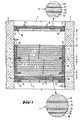
- Fig. 1 eine Verglasung mit insgesamt vier Verbundglaseinheiten in einer Schnittdarstellung und vergrößerten Detailschnittaufbrüchen, die den Aufbau der Verbundglaseinheiten darstellen, und
- Fig. 2 eine Verglasung mit insgesamt sechs Verbundglaseinheiten, ebenfalls in einer Schnittdarstellung.
- Fig. 1 is a glazing with a total of four laminated glass units in a sectional view and enlarged detail sections, which represent the structure of the laminated glass units, and
- Fig. 2 is a glazing with a total of six laminated glass units, also in a sectional view.
Die einzelnen Verbundglaseinheiten des Fensters sind in der Fensteröffnung 1 der Wand 2 mit Mitteln gehalten, die der besseren übersicht wegen nicht dargestellt sind. Dabei kann es sich um bekannte und übliche Haltekonstruktionen handeln.The individual laminated glass units of the window are held in the window opening 1 of the
Das in Fig. 1 dargestellte Fenster umfaßt zwei Verbundglaseinheiten 4,5 von je 12o mm Dicke. Jede Verbundglaseinheit 5 besteht aus sechs Einzelglasscheiben aus Floatglas von 19 mm Dicke, die mittels o,78 mm dicken Folien aus thermoplastischem Polyvinylbutyral miteinander verbunden sind.The window shown in Fig. 1 comprises two laminated glass units 4.5, each with a thickness of 120 mm. Each laminated glass unit 5 consists of six individual glass panes made of float glass 19 mm thick, which are connected to one another by means of 0.78 mm thick films made of thermoplastic polyvinyl butyral.
Jede Verbundglaseinheit 4,5 ist von einem Stahlrahmen 1o aus einem L-Profil umgeben. Der längere Schenkel 11 des L-Profils hat eine Länge von 15o mm, und der kürzere Schenkel 12, der die Verbundglaseinheit auf dem Randbereich der Sichtfläche abstützt, hat eine Länge von 75 mm. Die Wandstärke des L-Profils beträgt 1o mm. Die einzelnen Profilabschnitte des Stahlrahmens 1o sind an den Ecken zusammengeschweißt.Each laminated glass unit 4, 5 is surrounded by a
Im vorderen Endbereich des Schenkels 12 der Rahmenprofile ist zwischen diesem und der Verbundglasscheibe ein Profilstreifen 14 aus einem dauerelastischen Material angeordnet. Als Material hierfür eignet sich beispielsweise Butylkautschuk. Dieser Profilstreifen 14 wird in den Rahmen 10 eingelegt, bevor die Verbundglaseinheit in den Rahmen eingesetzt wird. Der Profilstreifen 14 hat einerseits die Aufgabe, die Verbundglasscheibe in dem erforderlichen Abstand C von dem Rahmen zu halten, und dient andererseits dazu, den beim Einsetzen der Verbundglasscheibe zwischen dieser und dem Rahmen entstehenden Hohlraum so abzudichten, daß dieser Hohlraum mit einer gießfähigen Kunststoffmasse 15 ausgefüllt werden kann. Der Profilstreifen 14 hat einen Durchmesser bzw. eine Kantenlänge von etwa 15 mm. Der Stahlrahmen 10 und die Verbundglasscheibe 4 sind in ihrer Größe so aufeinander abgestimmt, daß der zwischen der Verbundglasscheibe 4, dem Stahlrahmen 1o und dem Schenkel 11 entstehende Hohlraum eine Breite C von ebenfalls etwa 15 mm hat.In the front end region of the
Dieser von dem Randbereich der Verbundglasscheibe 4, dem Stahlrahmen 1o und dem Profilstreifen 14 gebildete Hohlraum wird mit einem gießfähigen Silikonkautschuk 15 ausgegossen, der nach dem Aushärten eine Endhärte von 3o bis 35 Grad Shore aufweist. Für diesen Zweck eignet sich z.B. der Zweikomponenten-Silikonkautschuk RTV E 6o2 der Firma Wacker-Chemie in München.This cavity formed by the edge area of the laminated glass pane 4, the
Um eine dauerhafte gute Haftung zwischen dem Silikonkautschuk und dem Glas bzw. dem Stahlrahmen zu gewährleisten, können die Glas- und Stahlflächen zuvor in bekannter Weise mit einem für das jeweils verwendete gießfähige Material geeigneten Primer versehen werden. Für den oben genannten Silikonkautschuk eignet sich beispielsweise der Primer G 79o der Firma Wacker-Chemie.In order to ensure permanent good adhesion between the silicone rubber and the glass or the steel frame, the glass and steel surfaces can be provided beforehand in a known manner with a primer suitable for the pourable material used in each case. The G 79o primer from Wacker-Chemie, for example, is suitable for the above-mentioned silicone rubber.
Die beiden jeweils mit einem Stahlrahmen umgebenen Verbundglaseinheiten 4,5 werden so in die Fensteröffnung 1 eingesetzt, daß der Abstand A zwischen den beiden benachbarten Glasoberflächen etwa 3o mm beträgt.The two, each surrounded by a steel frame Laminated glass units 4, 5 are inserted into the window opening 1 in such a way that the distance A between the two adjacent glass surfaces is approximately 30 mm.
Auf der der Explosion abgewandten Seite des Fensters ist vor der Verbundglaseinheit 5 ebenfalls mit einem Abstand A von etwa 3o mm eine weitere Verbundglaseinheit 7 angeordnet, die auf die gleiche Weise mit einem Stahlrahmen 17 aus miteinander verschweißten Winkelprofilen versehen ist wie die Verbundglaseinheiten 4 und 5. Auch bei dieser Verbundglaseinheit 7 ist ein Zwischenraum C von 1o bis 2o mm Breite mit einem dauerelastischen Material 15 ausgefüllt. Die Verbundglaseinheit 7 hat, von der Explosionsseite her gesehen, folgenden Aufbau: 12 mm dicke Glasscheibe 3o - 3 mm dicke Polyvinylbutyralschicht 31 - 12 mm dicke Glasscheibe 3o - 3 mm dicke Polyvinylbutyralschicht 33 - 6 mm dicke Glasscheibe 34 - 1,5 mm dicke Polyvinylbutyralschicht 35 - 6 mm dicke Glasscheibe 36. Diese Verbundglaseinheit 7 kann durch plastische Verformung der Polyvinylbutyralschichten noch vorhandene Restenergien aufnehmen. Sie dient außerdem zum Abfangen der Splitter, die sich von der dahinterliegenden Verbundglaseinheit lösen.On the side of the window facing away from the explosion, another laminated
Auf der dem Explosionsherd zugewandten Seite des Fensters ist in einem verhältnismäßig großen Abstand B vor der Verbundglaseinheit 4 eine weitere Verbundglaseinheit 8 angeordnet. Auch diese Verbundglaseinheit 8 ist von einem Stahlrahmen 18 umgeben, der wiederum aus miteinander verschweißten Profilabschnitten besteht. Die Verbundglaseinheit 8 besteht aus drei Einzelglasscheiben 4o aus 8 mm dickem Floatglas, die durch eine o,76 mm dicke Schicht 41 und eine 3 mm dicke Schicht 42, jeweils aus Polyvinylbutyral, miteinander verbunden sind. Diese Verbundglaseinheit-8 hat eine ausgeprägte einbruchhemmende Wirkung. Sie soll verhindern, daß der Sprengsatz unmittelbar vor den eigentlichen Explosionsschutzscheiben 4,5 angebracht werden kann. Der Abstand B zwischen dieser Verbundglasscheibe 8 und der Verbundglasscheibe 4 beträgt etwa 15o mm.A further laminated
In der Fig. 2 ist ein anderes explosionssicheres Fenster dargestellt, das grundsätzlich aus den gleichen Verbundglaselementen aufgebaut ist wie das in Fig. 1 dargestellte Fenster. Es umfaßt drei jeweils etwa 12o mm dicke Verbundglaseinheiten 4,5,6, die mit einem Luftabstand A von jeweils etwa 3o mm angeordnet sind. Vor diesen drei dicken Verbundglaseinheiten ist wiederum ebenfalls mit einem Luftabstand A von etwa 3o mm die im wesentlichen für den Splitterauffang und für die Vernichtung der Restenergie vorgesehene Verbundglasscheibe 7 angeordnet.Another explosion-proof window is shown in FIG. 2, which is basically constructed from the same laminated glass elements as the window shown in FIG. 1. It comprises three laminated
Auf der dem Explosionsherd zugewandten Seite des Fensters ist vor der Verbundglasscheibe 8 im Abstand von etwa 15o mm eine weitere Verbundglasscheibe 2o angeordnet, die auf die gleiche Weise wie alle anderen Verbundglaseinheiten von einem geschlossenen Stahlrahmen 18 umgeben und in diesem federnd gelagert ist. Diese Verbundglasscheibe 2o entspricht in ihrem Aufbau der Verbundglasscheibe 8. Durch die doppelte Anordnung einer solchen einbruchhemmenden Verbundglasscheibe wird die Sicherheit gegen die Anbringung des Sprengkörpers unmittelbar vor den massiven Explosionsschutzscheiben weiter erhöht.On the side of the window facing the explosion source, a further laminated glass pane 2o is arranged in front of the laminated
Claims (12)
Priority Applications (1)
| Application Number | Priority Date | Filing Date | Title |
|---|---|---|---|
| AT81109984T ATE9242T1 (en) | 1980-12-05 | 1981-11-28 | BLAST RESISTANT GLAZING MADE OF LAMINATED GLASS. |
Applications Claiming Priority (2)
| Application Number | Priority Date | Filing Date | Title |
|---|---|---|---|
| DE3045833 | 1980-12-05 | ||
| DE19803045833 DE3045833A1 (en) | 1980-12-05 | 1980-12-05 | BLAST-RESISTANT GLAZING MADE OF COMPOSITE GLASS |
Publications (2)
| Publication Number | Publication Date |
|---|---|
| EP0053774A1 true EP0053774A1 (en) | 1982-06-16 |
| EP0053774B1 EP0053774B1 (en) | 1984-09-05 |
Family
ID=6118356
Family Applications (1)
| Application Number | Title | Priority Date | Filing Date |
|---|---|---|---|
| EP81109984A Expired EP0053774B1 (en) | 1980-12-05 | 1981-11-28 | Explosion resisting glazing with laminated glass |
Country Status (3)
| Country | Link |
|---|---|
| EP (1) | EP0053774B1 (en) |
| AT (1) | ATE9242T1 (en) |
| DE (2) | DE3045833A1 (en) |
Cited By (2)
| Publication number | Priority date | Publication date | Assignee | Title |
|---|---|---|---|---|
| EP2110238A1 (en) * | 2008-04-17 | 2009-10-21 | Sälzer Sicherheitstechnik GmbH | Blast effect-limiting glazing structure |
| EP2278107A2 (en) * | 2009-07-02 | 2011-01-26 | Jeld-Wen Danmark A/S | Metallic frame for enclosing a door or a window |
Families Citing this family (5)
| Publication number | Priority date | Publication date | Assignee | Title |
|---|---|---|---|---|
| DE3420883C2 (en) * | 1983-07-28 | 1985-07-18 | Heinrich 3550 Marburg Sälzer | Blast-resistant glazing |
| DE3545173A1 (en) * | 1985-12-20 | 1987-06-25 | Siegfried Bauer | Window arrangement designed such that it can stem the effects of explosion |
| DE3744816C2 (en) * | 1987-02-20 | 1991-03-07 | Saelzer Sicherheitstechnik Gmbh, 3550 Marburg, De | Explosion-resistant glazing |
| DE3717527A1 (en) * | 1987-05-25 | 1988-12-22 | Erich Runkel | Explosion-proof window arrangement |
| DE19506733C2 (en) * | 1995-02-27 | 1998-03-19 | Rudolf Bieraeugel Stahl Und Me | Bulletproof arrangement for windows or doors |
Citations (6)
| Publication number | Priority date | Publication date | Assignee | Title |
|---|---|---|---|---|
| FR1515955A (en) * | 1965-10-20 | 1968-06-13 | Ucb Sa | Glazing sealing process |
| US3393485A (en) * | 1966-03-23 | 1968-07-23 | Rysdon Products Company | Impact-proof observation window |
| DE1659688A1 (en) * | 1966-12-17 | 1969-10-30 | Gold U Silber Scheide Anstalt | Multi-layer plastic disc or block |
| CH504610A (en) * | 1970-05-26 | 1971-03-15 | Beratung Patent Und Urheberrec | Bulletproof glass |
| US4027443A (en) * | 1975-10-14 | 1977-06-07 | Aneomstat Products Division, Dynamics Corporation Of America | Fire and impact resistant window assembly |
| GB1573936A (en) * | 1976-03-18 | 1980-08-28 | Nippon Sheet Glass Co Ltd | Method for fixing a glass sheet in sash frame and an assembly of the glass sheet and sash frame |
-
1980
- 1980-12-05 DE DE19803045833 patent/DE3045833A1/en not_active Withdrawn
-
1981
- 1981-11-28 AT AT81109984T patent/ATE9242T1/en not_active IP Right Cessation
- 1981-11-28 DE DE8181109984T patent/DE3165873D1/en not_active Expired
- 1981-11-28 EP EP81109984A patent/EP0053774B1/en not_active Expired
Patent Citations (6)
| Publication number | Priority date | Publication date | Assignee | Title |
|---|---|---|---|---|
| FR1515955A (en) * | 1965-10-20 | 1968-06-13 | Ucb Sa | Glazing sealing process |
| US3393485A (en) * | 1966-03-23 | 1968-07-23 | Rysdon Products Company | Impact-proof observation window |
| DE1659688A1 (en) * | 1966-12-17 | 1969-10-30 | Gold U Silber Scheide Anstalt | Multi-layer plastic disc or block |
| CH504610A (en) * | 1970-05-26 | 1971-03-15 | Beratung Patent Und Urheberrec | Bulletproof glass |
| US4027443A (en) * | 1975-10-14 | 1977-06-07 | Aneomstat Products Division, Dynamics Corporation Of America | Fire and impact resistant window assembly |
| GB1573936A (en) * | 1976-03-18 | 1980-08-28 | Nippon Sheet Glass Co Ltd | Method for fixing a glass sheet in sash frame and an assembly of the glass sheet and sash frame |
Cited By (2)
| Publication number | Priority date | Publication date | Assignee | Title |
|---|---|---|---|---|
| EP2110238A1 (en) * | 2008-04-17 | 2009-10-21 | Sälzer Sicherheitstechnik GmbH | Blast effect-limiting glazing structure |
| EP2278107A2 (en) * | 2009-07-02 | 2011-01-26 | Jeld-Wen Danmark A/S | Metallic frame for enclosing a door or a window |
Also Published As
| Publication number | Publication date |
|---|---|
| ATE9242T1 (en) | 1984-09-15 |
| DE3165873D1 (en) | 1984-10-11 |
| EP0053774B1 (en) | 1984-09-05 |
| DE3045833A1 (en) | 1982-07-08 |
Similar Documents
| Publication | Publication Date | Title |
|---|---|---|
| DE3432021A1 (en) | SECURITY WINDOW OR DOOR | |
| EP0109566A2 (en) | Bullet-proof laminated glass insert for observation slits in armoured vehicles | |
| EP0024713A2 (en) | Composite panel for armouring the interiors of vehicles or the like | |
| EP0053774A1 (en) | Explosion resisting glazing with laminated glass | |
| EP0505934B1 (en) | Glazed fire door | |
| DE2950348C2 (en) | ||
| DE2061569A1 (en) | Bullet proof cpd transparent sheet - comprising impact resisting plastic and foil re-inforced safety glass sheets | |
| DE202010009999U1 (en) | Modular fire-resistant glazing | |
| EP0634557A2 (en) | Door frame with fire-protective strip | |
| EP0528354A1 (en) | Bullet-proof insulating glazing unit | |
| EP2863001B1 (en) | Frameless glass door for fire protection purposes | |
| DE19809629A1 (en) | Device for protecting the interior of a combat vehicle, in particular a main battle tank, against heating up by solar radiation | |
| CH635052A5 (en) | Multiple glazing system which is resistant to the exertion of force | |
| EP1435424B1 (en) | Glass wall | |
| DE7722183U1 (en) | PANEL MADE OF TANK GLASS, ESPECIALLY FOR MOTOR VEHICLES | |
| DE9111130U1 (en) | Motor vehicle with armored window | |
| EP0531913B1 (en) | Motor vehicle with armoured glass | |
| DE2906975A1 (en) | Window or door frame profile bullet proof shield - has light inner and outer skins enclosing heavy steel armour plate | |
| DE2856085C2 (en) | Bulletproof panel assembly for security purposes | |
| DE2819658A1 (en) | Bullet-proof window pane frame - has strip and spacer linking overlap shanks, providing equal vertical and angled protection | |
| DE2304150A1 (en) | Fluorescent screen for X-ray purposes - having electrically insulating support, luminescent layer, and three antistatic layers on support and luminescent layer | |
| DE9400536U1 (en) | Glass door for fire protection purposes | |
| DE9107334U1 (en) | Strip to protect windows and doors during plastering | |
| DE2824199A1 (en) | Bulletproof glass pane joint - with bullet-proof frame by deflecting armour plate strip | |
| DE9106478U1 (en) | Fire-resistant glazing |
Legal Events
| Date | Code | Title | Description |
|---|---|---|---|
| PUAI | Public reference made under article 153(3) epc to a published international application that has entered the european phase |
Free format text: ORIGINAL CODE: 0009012 |
|
| AK | Designated contracting states |
Designated state(s): AT BE CH DE FR GB IT LI LU NL SE |
|
| 17P | Request for examination filed |
Effective date: 19820628 |
|
| RAP1 | Party data changed (applicant data changed or rights of an application transferred) |
Owner name: VEGLA VEREINIGTE GLASWERKE GMBH |
|
| ITF | It: translation for a ep patent filed | ||
| GRAA | (expected) grant |
Free format text: ORIGINAL CODE: 0009210 |
|
| AK | Designated contracting states |
Designated state(s): AT BE CH DE FR GB IT LI LU NL SE |
|
| PG25 | Lapsed in a contracting state [announced via postgrant information from national office to epo] |
Ref country code: SE Effective date: 19840905 Ref country code: NL Effective date: 19840905 Ref country code: BE Effective date: 19840905 |
|
| REF | Corresponds to: |
Ref document number: 9242 Country of ref document: AT Date of ref document: 19840915 Kind code of ref document: T |
|
| REF | Corresponds to: |
Ref document number: 3165873 Country of ref document: DE Date of ref document: 19841011 |
|
| PG25 | Lapsed in a contracting state [announced via postgrant information from national office to epo] |
Ref country code: AT Effective date: 19841128 |
|
| PG25 | Lapsed in a contracting state [announced via postgrant information from national office to epo] |
Ref country code: CH Effective date: 19841130 Ref country code: LU Free format text: LAPSE BECAUSE OF NON-PAYMENT OF DUE FEES Effective date: 19841130 Ref country code: LI Effective date: 19841130 |
|
| ET | Fr: translation filed | ||
| NLV1 | Nl: lapsed or annulled due to failure to fulfill the requirements of art. 29p and 29m of the patents act | ||
| PLBE | No opposition filed within time limit |
Free format text: ORIGINAL CODE: 0009261 |
|
| STAA | Information on the status of an ep patent application or granted ep patent |
Free format text: STATUS: NO OPPOSITION FILED WITHIN TIME LIMIT |
|
| REG | Reference to a national code |
Ref country code: CH Ref legal event code: PL |
|
| 26N | No opposition filed | ||
| PGFP | Annual fee paid to national office [announced via postgrant information from national office to epo] |
Ref country code: FR Payment date: 19890921 Year of fee payment: 9 |
|
| ITTA | It: last paid annual fee | ||
| PGFP | Annual fee paid to national office [announced via postgrant information from national office to epo] |
Ref country code: GB Payment date: 19891130 Year of fee payment: 9 |
|
| PGFP | Annual fee paid to national office [announced via postgrant information from national office to epo] |
Ref country code: DE Payment date: 19900116 Year of fee payment: 9 |
|
| PG25 | Lapsed in a contracting state [announced via postgrant information from national office to epo] |
Ref country code: GB Effective date: 19901128 |
|
| GBPC | Gb: european patent ceased through non-payment of renewal fee | ||
| PG25 | Lapsed in a contracting state [announced via postgrant information from national office to epo] |
Ref country code: DE Effective date: 19910801 |
|
| PG25 | Lapsed in a contracting state [announced via postgrant information from national office to epo] |
Ref country code: FR Effective date: 19920731 |
|
| REG | Reference to a national code |
Ref country code: FR Ref legal event code: ST |
|
| PG25 | Lapsed in a contracting state [announced via postgrant information from national office to epo] |
Ref country code: FR Effective date: 19901130 |