EP0053614B1 - Multiple spindle flexible sanding head - Google Patents
Multiple spindle flexible sanding head Download PDFInfo
- Publication number
- EP0053614B1 EP0053614B1 EP81901453A EP81901453A EP0053614B1 EP 0053614 B1 EP0053614 B1 EP 0053614B1 EP 81901453 A EP81901453 A EP 81901453A EP 81901453 A EP81901453 A EP 81901453A EP 0053614 B1 EP0053614 B1 EP 0053614B1
- Authority
- EP
- European Patent Office
- Prior art keywords
- abrading
- support member
- housing
- spindle
- discs
- Prior art date
- Legal status (The legal status is an assumption and is not a legal conclusion. Google has not performed a legal analysis and makes no representation as to the accuracy of the status listed.)
- Expired
Links
Images


Classifications
-
- B—PERFORMING OPERATIONS; TRANSPORTING
- B24—GRINDING; POLISHING
- B24B—MACHINES, DEVICES, OR PROCESSES FOR GRINDING OR POLISHING; DRESSING OR CONDITIONING OF ABRADING SURFACES; FEEDING OF GRINDING, POLISHING, OR LAPPING AGENTS
- B24B41/00—Component parts such as frames, beds, carriages, headstocks
- B24B41/04—Headstocks; Working-spindles; Features relating thereto
- B24B41/047—Grinding heads for working on plane surfaces
-
- B—PERFORMING OPERATIONS; TRANSPORTING
- B23—MACHINE TOOLS; METAL-WORKING NOT OTHERWISE PROVIDED FOR
- B23Q—DETAILS, COMPONENTS, OR ACCESSORIES FOR MACHINE TOOLS, e.g. ARRANGEMENTS FOR COPYING OR CONTROLLING; MACHINE TOOLS IN GENERAL CHARACTERISED BY THE CONSTRUCTION OF PARTICULAR DETAILS OR COMPONENTS; COMBINATIONS OR ASSOCIATIONS OF METAL-WORKING MACHINES, NOT DIRECTED TO A PARTICULAR RESULT
- B23Q11/00—Accessories fitted to machine tools for keeping tools or parts of the machine in good working condition or for cooling work; Safety devices specially combined with or arranged in, or specially adapted for use in connection with, machine tools
- B23Q11/0042—Devices for removing chips
- B23Q11/0046—Devices for removing chips by sucking
Definitions
- the invention relates to an abrading apparatus as defined in the introductory part of claim 1.
- Such an apparatus is known from DE-C-118 262.
- these heads are capable of adjusting to the surface to be abraded.
- the abrading heads are mounted to the shafts by means of the self-aligning bearings and the shafts themselves are mounted in rotating bearings in the support member.
- the gear train wheels mounted on the ends of the shafts are driven by a central gear wheel in engagement therewith.
- the invention has for its object to provide an apparatus of the kind set forth above which is of a more simple construction.
- the self-aligning bearing provides for the function of the alignment of the abrading head and also for the rotatable mounting of the shaft.
- the flexible drive means allow the swinging of the abrading head with its shaft and sprocket.
- An abrading head 10 has a housing 12 open ended on one direction to act like a hood.
- a support member 14 with inner member 14a and outer member 14b is located in the housing.
- the outer support member 14b has a series of spaced apart openings 16 shaped like an outward extending frustum of a cone.
- a free floating cylindrical shaped member or head 18 is sized to fit in each opening.
- These members have an abrasive disc 20 on the outer end and an enlarged diameter 22 at the other end.
- Each cylindrical shaped member is continuously being urged outward by a compression spring 24 mounted to the inner support member 14a to continually press the abrasive disc into contact with and to follow the contour of the surface 26 to be abraded.
- a series of openings 28a are located in inner support member 14a and a series of openings 28b are located in outer support member 14b to provide communication between the surface 26 and chamber 32 formed inside the housing 12.
- a coupling 34 extends through the housing 12, joins to an elbow 36 and a flexible hose 38 for connection to a vacuum source, not shown.
- a bushing 40 is centrally located in the closed end of the housing and extends inward toward the support member.
- a gear case 42 joins to the bushing then connects to an air motor 44 which is fed from a source of compressed air, not shown, through line 46.
- the air motor drives shaft 46 which acts through bevel gears 48 and 50 to drive shaft 52; which rotates inside the bushing 40.
- the drive shaft 52 is also joined to a sleeve 54; which acts to join the inner and outer support members for rotating the abrasive discs in response to action by the motor.
- handle 56 is fastened to the gear case to provide hand operation of the abrading head.
- it is not intended to limit this to a hand held operation as the positioning of the head may also be accomplished by any known automatic means, such as, by use of programmed cylinder actuation.
- the abrading head 10 is positioned with the abrasive discs 20 contacting surface 26to be abraded.
- the air motor 44 is turned on to rotate the support members with abrasive discs and the head moves with respect to the surface until the required amount of material has been removed from that surface.
- the vacuum source is also turned on to remove the debris.
- FIGS. 5-7 show another embodiment of this invention where each abrading disc or head is individually rotated.
- Housing 58 acts as a hood, has a chamber 60 and an enlarged area 62 where connector 64 is joined for communication with a vacuum source, not shown.
- a support member 66 is made up of an upper plate 66a joined by fasteners 68 to a formed member 66b. This support member, in turn, is joined by fastener 70 to the inside of the housing.
- a series of self-aligning spherical bearings 72 are mounted to the formed member 66b.
- An abrasive disc 74, with spindle or rod 76 is joined to the spherical bearing with the disc extending outward and a sprocket 78 mounted to the inside end of the spindle.
- a drive shaft 80 is mounted to rotate in a pair of ball bearings 82 and 84.
- the drive shaft has a drive gear 86 located to engage a gear 88 mounted on a driven roll 90.
- the driven roll also has a sprocket 92 and the roll is freely rotatable as it is held at the ends with ball bearings 94 and 96.
- a flexible drive belt 98 extends from the sprocket on the idler roll 90 and the sprockets 78 on the spindle rods 76.
- Drive shaft 80 accepts a shaft 100 which has a bevel gear 102 on the end to engage bevel gear 104. That gear is driven through rod 106 by a pneumatic motor 108. When this motor is turned on, the gear trains acts through driven gear 88 to rotate the driven roll with sprocket to move the belt and individually rotate each disc.
- the self-aligning spherical bearing in combination with the flexible belt permits the discs to individually align to follow the contour of surface 110.
- a resiliently mounted idler roll 112 is located to keep tension on the belt.
- a resilient barrier member 114 is located to lie outside the gear and drive system, and a pair of resilient barriers 116 are located near the inside of the flexible belt.
- a multiplicity of openings 118 extend through the support member 66. These openings are located outside barrier 114 and are also located inside barriers 116.
- the abrading head is placed with abrading discs on the surface 110.
- the air motor is turned on to individually rotate each disc 74 and a vacuum source is also turned on to pull debris through the support member into the housing chamber where the debris is removed through line 64.
Landscapes
- Engineering & Computer Science (AREA)
- Mechanical Engineering (AREA)
- Finish Polishing, Edge Sharpening, And Grinding By Specific Grinding Devices (AREA)
Abstract
Description
- The invention relates to an abrading apparatus as defined in the introductory part of claim 1.
- Such an apparatus is known from DE-C-118 262. By the mounting of the abrading heads with self-aligning bearings, these heads are capable of adjusting to the surface to be abraded. With this known apparatus the abrading heads are mounted to the shafts by means of the self-aligning bearings and the shafts themselves are mounted in rotating bearings in the support member. The gear train wheels mounted on the ends of the shafts are driven by a central gear wheel in engagement therewith.
- The invention has for its object to provide an apparatus of the kind set forth above which is of a more simple construction.
- In an abrading apparatus according to the invention this is achieved with the measures of the characterizing part of claim 1. In this way the self-aligning bearing provides for the function of the alignment of the abrading head and also for the rotatable mounting of the shaft. The flexible drive means allow the swinging of the abrading head with its shaft and sprocket.
-
- FIG. 1 shows a perspective top view of an abrading head of this invention.
- FIG. 2 shows a bottom perspective view of the abrading head of this invention.
- FIG. 3 shows a bottom view of the abrading head of this invention.
- FIG. 4 shows a side elevational sectional view taken along lines 4-4 of FIG. 3.
- FIG. 5 shows a bottom view of a different embodiment of this invention with abrading heads shown in phantom and the structure partially cut away to permit a better view of the drive system.
- FIG. 6 shows a fragmented, side elevational, sectional view taken along lines 6-6 of FIG. 5.
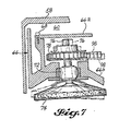
- FIG. 7 shows an enlarged fragmented view of FIG. 6.
- An abrading
head 10 has ahousing 12 open ended on one direction to act like a hood. Asupport member 14 with inner member 14a and outer member 14b is located in the housing. The outer support member 14b has a series of spaced apartopenings 16 shaped like an outward extending frustum of a cone. A free floating cylindrical shaped member orhead 18 is sized to fit in each opening. These members have anabrasive disc 20 on the outer end and an enlargeddiameter 22 at the other end. Each cylindrical shaped member is continuously being urged outward by acompression spring 24 mounted to the inner support member 14a to continually press the abrasive disc into contact with and to follow the contour of thesurface 26 to be abraded. A series ofopenings 28a are located in inner support member 14a and a series ofopenings 28b are located in outer support member 14b to provide communication between thesurface 26 andchamber 32 formed inside thehousing 12. Acoupling 34 extends through thehousing 12, joins to anelbow 36 and aflexible hose 38 for connection to a vacuum source, not shown. - A
bushing 40 is centrally located in the closed end of the housing and extends inward toward the support member. Agear case 42 joins to the bushing then connects to anair motor 44 which is fed from a source of compressed air, not shown, throughline 46. The air motor drivesshaft 46 which acts throughbevel gears shaft 52; which rotates inside thebushing 40. Thedrive shaft 52 is also joined to asleeve 54; which acts to join the inner and outer support members for rotating the abrasive discs in response to action by the motor. In this embodiment,handle 56 is fastened to the gear case to provide hand operation of the abrading head. However, it is not intended to limit this to a hand held operation as the positioning of the head may also be accomplished by any known automatic means, such as, by use of programmed cylinder actuation. - In operation, the abrading
head 10 is positioned with theabrasive discs 20 contacting surface 26to be abraded. Theair motor 44 is turned on to rotate the support members with abrasive discs and the head moves with respect to the surface until the required amount of material has been removed from that surface. The vacuum source is also turned on to remove the debris. - FIGS. 5-7 show another embodiment of this invention where each abrading disc or head is individually rotated.
Housing 58 acts as a hood, has achamber 60 and an enlargedarea 62 whereconnector 64 is joined for communication with a vacuum source, not shown. Asupport member 66 is made up of an upper plate 66a joined byfasteners 68 to a formed member 66b. This support member, in turn, is joined by fastener 70 to the inside of the housing. - A series of self-aligning
spherical bearings 72 are mounted to the formed member 66b. Anabrasive disc 74, with spindle orrod 76 is joined to the spherical bearing with the disc extending outward and asprocket 78 mounted to the inside end of the spindle. Adrive shaft 80 is mounted to rotate in a pair ofball bearings drive gear 86 located to engage agear 88 mounted on a drivenroll 90. The driven roll also has asprocket 92 and the roll is freely rotatable as it is held at the ends withball bearings flexible drive belt 98 extends from the sprocket on theidler roll 90 and thesprockets 78 on thespindle rods 76.Drive shaft 80 accepts ashaft 100 which has abevel gear 102 on the end to engagebevel gear 104. That gear is driven throughrod 106 by apneumatic motor 108. When this motor is turned on, the gear trains acts through drivengear 88 to rotate the driven roll with sprocket to move the belt and individually rotate each disc. The self-aligning spherical bearing in combination with the flexible belt permits the discs to individually align to follow the contour ofsurface 110. A resiliently mounted idler roll 112 is located to keep tension on the belt. - A
resilient barrier member 114 is located to lie outside the gear and drive system, and a pair ofresilient barriers 116 are located near the inside of the flexible belt. A multiplicity ofopenings 118 extend through thesupport member 66. These openings are located outsidebarrier 114 and are also located insidebarriers 116. - To operate this embodiment, the abrading head is placed with abrading discs on the
surface 110. The air motor is turned on to individually rotate eachdisc 74 and a vacuum source is also turned on to pull debris through the support member into the housing chamber where the debris is removed throughline 64.
Claims (5)
Applications Claiming Priority (2)
| Application Number | Priority Date | Filing Date | Title |
|---|---|---|---|
| US06/156,282 US4328645A (en) | 1980-06-04 | 1980-06-04 | Multiple spindle flexible sanding head |
| US156282 | 1980-06-04 |
Publications (3)
| Publication Number | Publication Date |
|---|---|
| EP0053614A1 EP0053614A1 (en) | 1982-06-16 |
| EP0053614A4 EP0053614A4 (en) | 1984-08-10 |
| EP0053614B1 true EP0053614B1 (en) | 1986-12-30 |
Family
ID=22558904
Family Applications (1)
| Application Number | Title | Priority Date | Filing Date |
|---|---|---|---|
| EP81901453A Expired EP0053614B1 (en) | 1980-06-04 | 1981-05-04 | Multiple spindle flexible sanding head |
Country Status (3)
| Country | Link |
|---|---|
| US (1) | US4328645A (en) |
| EP (1) | EP0053614B1 (en) |
| WO (1) | WO1981003455A1 (en) |
Families Citing this family (40)
| Publication number | Priority date | Publication date | Assignee | Title |
|---|---|---|---|---|
| US4499624A (en) * | 1983-02-25 | 1985-02-19 | The Kartridg Pak Company | Portable polisher |
| US4570278A (en) * | 1983-02-25 | 1986-02-18 | The Kartridg Pak Co. | Portable polisher and buffs therefor |
| IT1169618B (en) * | 1983-10-27 | 1987-06-03 | Dmc Div Mecc Cast | SANDING MACHINE FOR WOOD PANELS |
| US4616449A (en) * | 1984-08-31 | 1986-10-14 | Miksa Marton | Suction housing for vacuum sanding devices |
| FR2584011B1 (en) * | 1985-06-28 | 1989-02-24 | Renault | BRUSHING HEAD, ESPECIALLY FOR MACHINING CENTERS |
| US4621462A (en) * | 1985-09-06 | 1986-11-11 | The Boeing Company | Dust collection apparatus |
| US4766701A (en) * | 1986-09-02 | 1988-08-30 | Roestenberg Jerome R | Vacuum rasp |
| US4680895A (en) * | 1986-09-02 | 1987-07-21 | Roestenberg Jerome R | Block sander vacuum |
| US5027470A (en) * | 1990-10-09 | 1991-07-02 | Robert Takashima | Dustless surface treatment machine |
| US5518442A (en) | 1993-01-22 | 1996-05-21 | Porter-Cable Corporation | Sander |
| US5707273A (en) * | 1994-04-28 | 1998-01-13 | Timesavers, Inc. | Multiple-pad orbital sander with split pad platen |
| US5709597A (en) * | 1995-11-21 | 1998-01-20 | Sarantitis; Andreas I. | Pivotal vacuum shield for an abrading device |
| US5941765A (en) * | 1996-11-19 | 1999-08-24 | Porter Cable Corporation | Sander |
| NL1006141C1 (en) * | 1997-05-27 | 1998-12-01 | Holland Ind Diamantwerken Bv | Grinding machine. |
| DE19735936C1 (en) * | 1997-08-19 | 1998-09-24 | Unislip Gmbh | Fixed or mobile grinder head |
| US6139411A (en) * | 1998-03-03 | 2000-10-31 | Ryobi North America, Inc. | Disc sander |
| AUPP926799A0 (en) * | 1999-03-17 | 1999-04-15 | Mcnair, Susan Gail | Surface finishing machine |
| AUPQ652300A0 (en) * | 2000-03-27 | 2000-04-20 | Mcnair, Susan Gail | Surface finishing pad |
| US20040154168A1 (en) * | 2003-02-07 | 2004-08-12 | Mcdonald Jon Anthony | Dust and debris shield for powered hand tool |
| DE10317004A1 (en) * | 2003-04-11 | 2004-11-11 | Efco Maschinenbau Gmbh & Co. Kg | grinding head |
| CN1778066B (en) | 2003-04-24 | 2011-10-12 | 松下电器产业株式会社 | Apparatus to generate parameter for ntru, ntru decryption and encryption system, apparatus, method and program implementing said parameter generating unit |
| US6793567B1 (en) | 2003-05-07 | 2004-09-21 | Northrop Grumman Corporation | Upper outermold line sander |
| SE525224C2 (en) * | 2003-06-11 | 2004-12-28 | Htc Sweden Ab | Device for grinding a wall of stone or concrete material |
| DE102005062887A1 (en) * | 2005-12-29 | 2007-07-05 | Robert Bosch Gmbh | Hand-held machine tool e.g. boring machine, for driving e.g. boring tool, has transmission unit designed as single unit with tool retaining unit, and channel formed as single piece with turbine unit supply channel |
| US7458883B2 (en) * | 2006-01-31 | 2008-12-02 | B A Werk Industries Ltd. | Apparatus for abrading a surface |
| US7427228B1 (en) * | 2006-02-06 | 2008-09-23 | Cyrus W Kirsch | Handheld material conditioner |
| AU2007229923A1 (en) * | 2006-03-24 | 2007-10-04 | Blastrac N.A., Inc. | Device and method for extraction of dust from a grinder |
| US20080318506A1 (en) * | 2007-06-19 | 2008-12-25 | John Edward Brown | Abrasive article and method of making |
| US8147297B2 (en) * | 2009-01-26 | 2012-04-03 | Amano Pioneer Eclipse Corporation | Surface grinding machine and grinding head therefor |
| US8251780B2 (en) * | 2009-02-10 | 2012-08-28 | Amano Pioneer Eclipse Corporation | Floor grinding machine and grinding head unit therefor |
| US8366518B2 (en) * | 2010-02-11 | 2013-02-05 | Miles Supply, Inc. | Orbital smoothing device |
| US9089945B2 (en) * | 2010-02-11 | 2015-07-28 | Miles Supply, Inc. | Orbital smoothing device |
| EP2394784B1 (en) * | 2010-06-09 | 2012-11-28 | Design Technologies LLC | Rotatable disc head as well as floor treatment machine comprising such disk head |
| US8801506B2 (en) * | 2011-11-28 | 2014-08-12 | X'pole Precision Tools Inc. | Dust collection hood for grinding machine tools |
| US8715039B2 (en) * | 2011-11-28 | 2014-05-06 | X'pole Precision Tools Inc. | Machine tool providing a large grinding area |
| US10406648B2 (en) * | 2012-01-19 | 2019-09-10 | Newgrind Inc. | Apparatus for surface abrasion |
| DE202012002267U1 (en) * | 2012-03-07 | 2012-04-18 | Jakob Löwer Inh. von Schumann GmbH & Co. KG | Disc grinder of a device for deburring and / or rounding of metal workpieces in a continuous process |
| SE542092C2 (en) * | 2016-06-03 | 2020-02-25 | Husqvarna Ab | Grinding head for floor grinding machine and a floor grinding machine comprising such a grinding head |
| US10150196B2 (en) | 2016-08-10 | 2018-12-11 | The Boeing Company | Method and automated rover device for surface treatment |
| US10960510B2 (en) * | 2018-10-05 | 2021-03-30 | Diamond Productions Ltd. | Device for attaching drive plates to a powered floor polishing machine |
Family Cites Families (9)
| Publication number | Priority date | Publication date | Assignee | Title |
|---|---|---|---|---|
| DE118262C (en) * | ||||
| US1312235A (en) * | 1919-08-05 | Grinding ok polishing machine | ||
| US1622592A (en) * | 1922-11-13 | 1927-03-29 | Arthur B Kratz | Rubbing machine |
| US1581855A (en) * | 1925-05-21 | 1926-04-20 | May Ernest | Surface-rubbing machine |
| GB258768A (en) * | 1926-01-20 | 1926-09-30 | William Kynaston Couch | Improvements in or relating to grinding or polishing apparatus |
| US1928390A (en) * | 1932-05-28 | 1933-09-26 | American Floor Surfacing Mach | Planetary type surfacing machine |
| US3722147A (en) * | 1971-08-16 | 1973-03-27 | L Brenner | Air driven abrading device |
| DE2316957A1 (en) * | 1973-04-05 | 1974-10-17 | Uerdingen Ag Waggonfabrik | DEVICE FOR SANDING FLAT AND / OR SLIGHTLY CURVED SURFACES |
| US4058936A (en) * | 1976-01-20 | 1977-11-22 | Miksa Marton | Vacuum sander |
-
1980
- 1980-06-04 US US06/156,282 patent/US4328645A/en not_active Expired - Lifetime
-
1981
- 1981-05-04 EP EP81901453A patent/EP0053614B1/en not_active Expired
- 1981-05-04 WO PCT/US1981/000608 patent/WO1981003455A1/en active IP Right Grant
Also Published As
| Publication number | Publication date |
|---|---|
| WO1981003455A1 (en) | 1981-12-10 |
| US4328645A (en) | 1982-05-11 |
| EP0053614A1 (en) | 1982-06-16 |
| EP0053614A4 (en) | 1984-08-10 |
Similar Documents
| Publication | Publication Date | Title |
|---|---|---|
| EP0053614B1 (en) | Multiple spindle flexible sanding head | |
| US4809383A (en) | Device capable of adhering to a wall surface by suction and treating it | |
| US4860400A (en) | Device capable of adhering to a wall surface by suction and treating it | |
| US6238277B1 (en) | Multidisc floor grinder | |
| US4212237A (en) | Automatic asparagus peeling machine | |
| GB2067497A (en) | Improvements in or relating to the cleaning of a conveyor belt | |
| JP2003181755A (en) | Piping polishing device | |
| US2666282A (en) | Method of conditioning metal sheets, strips, rods, and the like | |
| US3887955A (en) | Headlight wiper | |
| AU687160B2 (en) | Manufacture of laminated windows | |
| CN113245994A (en) | Building engineering pipe fitting rust cleaning device | |
| US5134811A (en) | Apparatus for cleaning articles and method for cleaning articles | |
| US3906676A (en) | Rotary mechanical wire grinder | |
| US2092962A (en) | Sand blasting apparatus | |
| US3972152A (en) | Band-type polisher | |
| US4437202A (en) | Automatic wall cleaning machine | |
| CA1181232A (en) | Slag removal apparatus | |
| CN208409610U (en) | A kind of automatic sand shaker of glass | |
| CN112917356A (en) | Water conservancy construction pipeline surface rust cleaning device | |
| KR200343075Y1 (en) | Grooving machine | |
| US4139921A (en) | Device for cleaning floater oven nozzles | |
| US4872290A (en) | Glassware grinding and/or polishing apparatus | |
| JPS6222498Y2 (en) | ||
| SU1018747A1 (en) | Machine for straightening and cleaning elongated cylindrical articles | |
| JPS6225351Y2 (en) |
Legal Events
| Date | Code | Title | Description |
|---|---|---|---|
| PUAI | Public reference made under article 153(3) epc to a published international application that has entered the european phase |
Free format text: ORIGINAL CODE: 0009012 |
|
| 17P | Request for examination filed |
Effective date: 19820204 |
|
| AK | Designated contracting states |
Designated state(s): DE FR GB NL SE |
|
| GRAA | (expected) grant |
Free format text: ORIGINAL CODE: 0009210 |
|
| AK | Designated contracting states |
Kind code of ref document: B1 Designated state(s): DE FR GB NL SE |
|
| PG25 | Lapsed in a contracting state [announced via postgrant information from national office to epo] |
Ref country code: SE Effective date: 19861231 |
|
| ET | Fr: translation filed | ||
| REF | Corresponds to: |
Ref document number: 3175745 Country of ref document: DE Date of ref document: 19870205 |
|
| PLBE | No opposition filed within time limit |
Free format text: ORIGINAL CODE: 0009261 |
|
| STAA | Information on the status of an ep patent application or granted ep patent |
Free format text: STATUS: NO OPPOSITION FILED WITHIN TIME LIMIT |
|
| 26N | No opposition filed | ||
| PGFP | Annual fee paid to national office [announced via postgrant information from national office to epo] |
Ref country code: GB Payment date: 19900501 Year of fee payment: 10 |
|
| PGFP | Annual fee paid to national office [announced via postgrant information from national office to epo] |
Ref country code: NL Payment date: 19900531 Year of fee payment: 10 Ref country code: FR Payment date: 19900531 Year of fee payment: 10 Ref country code: DE Payment date: 19900531 Year of fee payment: 10 |
|
| PG25 | Lapsed in a contracting state [announced via postgrant information from national office to epo] |
Ref country code: GB Effective date: 19910504 |
|
| PG25 | Lapsed in a contracting state [announced via postgrant information from national office to epo] |
Ref country code: NL Effective date: 19911201 |
|
| GBPC | Gb: european patent ceased through non-payment of renewal fee | ||
| NLV4 | Nl: lapsed or anulled due to non-payment of the annual fee | ||
| PG25 | Lapsed in a contracting state [announced via postgrant information from national office to epo] |
Ref country code: FR Effective date: 19920131 |
|
| PG25 | Lapsed in a contracting state [announced via postgrant information from national office to epo] |
Ref country code: DE Effective date: 19920303 |
|
| REG | Reference to a national code |
Ref country code: FR Ref legal event code: ST |