EP0053534B1 - Gittermast, insbesondere als Träger für Antennen - Google Patents
Gittermast, insbesondere als Träger für Antennen Download PDFInfo
- Publication number
- EP0053534B1 EP0053534B1 EP81401806A EP81401806A EP0053534B1 EP 0053534 B1 EP0053534 B1 EP 0053534B1 EP 81401806 A EP81401806 A EP 81401806A EP 81401806 A EP81401806 A EP 81401806A EP 0053534 B1 EP0053534 B1 EP 0053534B1
- Authority
- EP
- European Patent Office
- Prior art keywords
- sleeves
- sockets
- uprights
- structure according
- panel
- Prior art date
- Legal status (The legal status is an assumption and is not a legal conclusion. Google has not performed a legal analysis and makes no representation as to the accuracy of the status listed.)
- Expired
Links
- 241000239290 Araneae Species 0.000 claims description 5
- 238000004519 manufacturing process Methods 0.000 claims description 2
- 238000000034 method Methods 0.000 claims 1
- 125000006850 spacer group Chemical group 0.000 description 14
- 239000011347 resin Substances 0.000 description 6
- 229920005989 resin Polymers 0.000 description 6
- 239000000463 material Substances 0.000 description 2
- 238000004026 adhesive bonding Methods 0.000 description 1
- 230000005540 biological transmission Effects 0.000 description 1
- 230000001413 cellular effect Effects 0.000 description 1
- 230000006835 compression Effects 0.000 description 1
- 238000007906 compression Methods 0.000 description 1
- 230000007797 corrosion Effects 0.000 description 1
- 238000005260 corrosion Methods 0.000 description 1
- 238000001125 extrusion Methods 0.000 description 1
- 239000003365 glass fiber Substances 0.000 description 1
- 238000002347 injection Methods 0.000 description 1
- 239000007924 injection Substances 0.000 description 1
- 239000012528 membrane Substances 0.000 description 1
- 239000002184 metal Substances 0.000 description 1
- 239000000615 nonconductor Substances 0.000 description 1
- 229920002635 polyurethane Polymers 0.000 description 1
- 239000004814 polyurethane Substances 0.000 description 1
- 239000012815 thermoplastic material Substances 0.000 description 1
- 238000003466 welding Methods 0.000 description 1
Images
Classifications
-
- H—ELECTRICITY
- H01—ELECTRIC ELEMENTS
- H01Q—ANTENNAS, i.e. RADIO AERIALS
- H01Q1/00—Details of, or arrangements associated with, antennas
- H01Q1/12—Supports; Mounting means
- H01Q1/1242—Rigid masts specially adapted for supporting an aerial
-
- E—FIXED CONSTRUCTIONS
- E04—BUILDING
- E04H—BUILDINGS OR LIKE STRUCTURES FOR PARTICULAR PURPOSES; SWIMMING OR SPLASH BATHS OR POOLS; MASTS; FENCING; TENTS OR CANOPIES, IN GENERAL
- E04H12/00—Towers; Masts or poles; Chimney stacks; Water-towers; Methods of erecting such structures
- E04H12/02—Structures made of specified materials
- E04H12/08—Structures made of specified materials of metal
- E04H12/10—Truss-like structures
-
- E—FIXED CONSTRUCTIONS
- E04—BUILDING
- E04H—BUILDINGS OR LIKE STRUCTURES FOR PARTICULAR PURPOSES; SWIMMING OR SPLASH BATHS OR POOLS; MASTS; FENCING; TENTS OR CANOPIES, IN GENERAL
- E04H12/00—Towers; Masts or poles; Chimney stacks; Water-towers; Methods of erecting such structures
- E04H12/18—Towers; Masts or poles; Chimney stacks; Water-towers; Methods of erecting such structures movable or with movable sections, e.g. rotatable or telescopic
- E04H12/185—Towers; Masts or poles; Chimney stacks; Water-towers; Methods of erecting such structures movable or with movable sections, e.g. rotatable or telescopic with identical elements
-
- Y—GENERAL TAGGING OF NEW TECHNOLOGICAL DEVELOPMENTS; GENERAL TAGGING OF CROSS-SECTIONAL TECHNOLOGIES SPANNING OVER SEVERAL SECTIONS OF THE IPC; TECHNICAL SUBJECTS COVERED BY FORMER USPC CROSS-REFERENCE ART COLLECTIONS [XRACs] AND DIGESTS
- Y10—TECHNICAL SUBJECTS COVERED BY FORMER USPC
- Y10T—TECHNICAL SUBJECTS COVERED BY FORMER US CLASSIFICATION
- Y10T403/00—Joints and connections
- Y10T403/34—Branched
- Y10T403/341—Three or more radiating members
- Y10T403/342—Polyhedral
-
- Y—GENERAL TAGGING OF NEW TECHNOLOGICAL DEVELOPMENTS; GENERAL TAGGING OF CROSS-SECTIONAL TECHNOLOGIES SPANNING OVER SEVERAL SECTIONS OF THE IPC; TECHNICAL SUBJECTS COVERED BY FORMER USPC CROSS-REFERENCE ART COLLECTIONS [XRACs] AND DIGESTS
- Y10—TECHNICAL SUBJECTS COVERED BY FORMER USPC
- Y10T—TECHNICAL SUBJECTS COVERED BY FORMER US CLASSIFICATION
- Y10T403/00—Joints and connections
- Y10T403/44—Three or more members connected at single locus
- Y10T403/443—All encompassed
Definitions
- the present invention relates to a trellis structure advantageously made of reinforced resin which can be used in particular as a mast for supporting high power antennas at significant heights, of several tens of meters.
- reinforced resin antenna masts are known compared to metal masts.
- the reinforced resin is non-magnetic and insulating and therefore does not create any electromagnetic disturbance. Its low density facilitates transport and handling. Its corrosion resistance allows very long lifetimes.
- the invention relates to a trellis structure, usable as a mast and which, made of reinforced resin, has a mechanical resistance comparable to that of metallic structures.
- US-A-3 100 555 discloses a tubular lattice structure, constituted by a plurality of continuous cylindrical uprights, assembled by braces constituted by members enveloping these uprights and fixed to them, provided with sockets receiving the ends of bracing struts.
- the invention aims to provide a structure of the type indicated above, but the assembly of which can be prepared in the factory and carried out in a simple manner at the place of use.
- the structure is divided into successive adjacent sections and that, in each section, the entire bracing is a rigid and independent module, like those described in DE-U-1 626 712, but comprising a plurality spacers engaged in sockets integral with the sleeves in which the uprights are threaded and which, on each side, constitute the ends of this module.
- bracing panels of the same section of the structure are assembled together in advance via said sleeves to form a module, the continuous series of adjacent modules being finally traversed by the frames and assembled therewith appropriately.
- each panel is constituted by four spacers, in the form of cylindrical bars, assembled in the same plane by a crosspiece comprising for this purpose four cross sockets.
- each sleeve open inside of it, their axes compete with each other and with the axis of the sleeve.
- this sleeve is limited, towards the neighboring module, by a plane perpendicular to its axis passing through the point of intersection of these axes.
- the diameter of the sleeve being larger than that of the sockets, it is possible for mounting the modules on a template to engage each of the spacers in its socket by passing through the sleeve and then advancing it to the crosspiece, this which avoids the difficulty of assembling a panel by engaging both the ends of the spacers in the sleeves for housing the sleeves and the spider and then gradually reducing the size of the geometric figure thus produced.
- the structure (beam or mast) may be of any length in one piece or formed of sections assembled by end-to-end connection of the sections of members, this assembly and the modes of use of the structures are not part of the invention.
- this mast is held in its erected position by a set of shrouds, not shown.
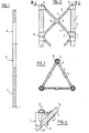
- the mast 1 is formed, in the example shown, of three identical structures A, B, C fixed end to end.
- Each structure can have three parallel members 2 arranged ( Figure 3) along the edges of a regular prism of triangular section.
- the members 2 are connected two by two by cross-shaped bracing panels 3. As shown in FIG. 2, this panel comprises four identical spacers 4 fixed by one end in the sockets 9 of a spider 5. The spacers 4 are engaged and fixed by their other end in the sockets 6 formed projecting from the sleeves 7 , threaded and fixed on the uprights 2.
- the sockets 6 are inclined at 45 ° relative to the axis of the sleeve 7 to correspond to the angles of the branches of the spider 5.
- each corner sleeve element 7 then comprises two sockets 6 situated in planes at 60 ° around the axis of the member.
- the sockets 6 integral with the same sleeve 7 open inside thereof, which allows to engage each spacer 4 from the inside of the sleeve 7, in its socket 6 until bringing it into the corresponding socket 9 of the spider 5.
- each point 0 becomes a point node of articulation of the lattice structure.
- the set of three panels of the same floor and the associated sleeves constitutes a bracing module, composed in this case of six sleeves 7, three cross-pieces 5 and twelve spacers 4.
- the bracing modules are joined, the sleeves 7 belonging to successive modules having their end faces 8 in contact. After which the members 2 are engaged in the sleeves 7 of the modules and fixed therein in an appropriate manner.
- Membranes, spacers and sleeves may be of any material provided that they are suitable for assembly by gluing, welding, keying, etc.
- all of these elements - frames, spacers, cross-pieces and sleeves - are made of fiber-reinforced resin, which allows for resistant bonding.
- the members and the spacers are tubes which can be obtained by "pultrusion", that is to say by extrusion combined with a traction exerted on the end of the tube during manufacture.
- they can be filled with a cellular material 10 forming an electrical insulator such as a polyurethane.
- the cross-pieces 5 and the sleeves 7 can be made of non-rigid thermoplastic material, loaded with glass fibers and injection molded. In this way, each of these elements can play in the structure the role of a joint within the meaning of the theory of articulated trusses; the embedding moments can be considered negligible and the knots being punctual, the spacers and the free portions of the members are stressed in tension or in compression.
- the sections once assembled in the factory are dismantled for transport, which therefore poses no problems.
- the invention applies to support masts, in particular for antennas, to provisional or definitive framework elements and other applications which must combine lightness and great range.
Landscapes
- Engineering & Computer Science (AREA)
- Architecture (AREA)
- Civil Engineering (AREA)
- Structural Engineering (AREA)
- Life Sciences & Earth Sciences (AREA)
- Chemical & Material Sciences (AREA)
- Materials Engineering (AREA)
- Wood Science & Technology (AREA)
- Support Of Aerials (AREA)
- Variable-Direction Aerials And Aerial Arrays (AREA)
- Rod-Shaped Construction Members (AREA)
Claims (7)
Priority Applications (1)
| Application Number | Priority Date | Filing Date | Title |
|---|---|---|---|
| AT81401806T ATE12560T1 (de) | 1980-12-01 | 1981-11-17 | Gittermast, insbesondere als traeger fuer antennen. |
Applications Claiming Priority (2)
| Application Number | Priority Date | Filing Date | Title |
|---|---|---|---|
| FR8025454 | 1980-12-01 | ||
| FR8025454A FR2495275B1 (fr) | 1980-12-01 | 1980-12-01 | Structure en treillis, en particulier mat-support d'antenne |
Publications (2)
| Publication Number | Publication Date |
|---|---|
| EP0053534A1 EP0053534A1 (de) | 1982-06-09 |
| EP0053534B1 true EP0053534B1 (de) | 1985-04-03 |
Family
ID=9248516
Family Applications (1)
| Application Number | Title | Priority Date | Filing Date |
|---|---|---|---|
| EP81401806A Expired EP0053534B1 (de) | 1980-12-01 | 1981-11-17 | Gittermast, insbesondere als Träger für Antennen |
Country Status (6)
| Country | Link |
|---|---|
| US (1) | US4437288A (de) |
| EP (1) | EP0053534B1 (de) |
| AT (1) | ATE12560T1 (de) |
| CA (1) | CA1183319A (de) |
| DE (1) | DE3169735D1 (de) |
| FR (1) | FR2495275B1 (de) |
Families Citing this family (24)
| Publication number | Priority date | Publication date | Assignee | Title |
|---|---|---|---|---|
| US4660345A (en) * | 1984-10-10 | 1987-04-28 | Mr. Gasket Company | Vehicle space frame, castings therefor and method for remote construction |
| US4735355A (en) * | 1984-10-10 | 1988-04-05 | Mr. Gasket Company | Method for construction of vehicle space frame |
| IL74479A (en) * | 1984-11-01 | 1994-04-12 | Koor Metal Ltd | Connects rods to create a spatial structure |
| US4745412A (en) * | 1985-05-10 | 1988-05-17 | Chu Associates, Inc. | Lightweight tower assemblies for antennas and the like |
| FR2588697B1 (fr) * | 1985-10-16 | 1988-07-08 | Heiligenstein Bernard | Antenne en reseau periodique logarithmique |
| US4878286A (en) * | 1985-12-12 | 1989-11-07 | General Electric Company | Truss structure and method for construction thereof |
| US4829739A (en) * | 1985-12-12 | 1989-05-16 | General Electric Company | Method for construction of a truss structure |
| US4803824A (en) * | 1985-12-12 | 1989-02-14 | General Electric Company | Truss structure and method and apparatus for construction thereof |
| EP0310478B1 (de) * | 1987-09-28 | 1991-04-24 | Electricite De France | Schalenkonstruktion und Herstellungsverfahren einer solchen Konstruktion |
| US4900050A (en) * | 1988-10-18 | 1990-02-13 | Huffy Corporation | Manufacture of bicycle frames |
| US5019312A (en) * | 1988-10-18 | 1991-05-28 | Huffy Corporation | Method for assembling a bicycle frame |
| US4930930A (en) * | 1988-12-21 | 1990-06-05 | General Electric Company | Truss beam attachment apparatus |
| DE3843996A1 (de) * | 1988-12-27 | 1990-06-28 | Zeppenfeld Aloys Gmbh | Mast fuer einen zahnstangenaufzug |
| US5794398A (en) * | 1992-08-25 | 1998-08-18 | Kaehler; Klaus | Framework with hollow members process for producing the same and its use |
| US5224320A (en) * | 1992-09-25 | 1993-07-06 | Mai Paul K | Space frame system |
| JPH08509275A (ja) * | 1993-01-21 | 1996-10-01 | ダブリュー. ジョンスン,デイビッド | 送電塔及びその他の大型構造物のための引出成形複合物継手システム |
| DE19616144C2 (de) * | 1996-04-23 | 1999-12-09 | Pfleiderer Verkehrstechnik | GFK-Mast |
| GB2335669B (en) * | 1998-03-26 | 2002-08-28 | Philip Rudolph Enos | Structural truss |
| DE10001399A1 (de) * | 2000-01-14 | 2001-08-16 | Horst Nowack | Gittertragwerk |
| FR2826990B1 (fr) * | 2001-07-09 | 2004-07-16 | Cap Co | Element de structure de type poutre treillis, et structure formee par l'assemblage de tels elements |
| FR2951218B1 (fr) * | 2009-10-12 | 2012-03-09 | Alcatel Lucent | Pylone de communication |
| CN104563913B (zh) * | 2015-01-12 | 2016-06-08 | 上海振华重工(集团)股份有限公司 | 套管张紧器平台框架及其套件 |
| US9896860B2 (en) * | 2015-07-12 | 2018-02-20 | iSIMS LLC | Structural support system and methods of use |
| CN116263062A (zh) * | 2022-12-22 | 2023-06-16 | 和勤通信技术有限公司 | 一种大板结构三角通信塔 |
Family Cites Families (26)
| Publication number | Priority date | Publication date | Assignee | Title |
|---|---|---|---|---|
| US349049A (en) | 1886-09-14 | Telegraph-pole | ||
| US490267A (en) | 1893-01-24 | buenhxm | ||
| US637420A (en) | 1899-06-05 | 1899-11-21 | Michael C Robbins | Tower for windmills. |
| US824501A (en) | 1902-07-03 | 1906-06-26 | Edmond Molloy | Tubular-metal structure. |
| US1162294A (en) | 1913-08-18 | 1915-11-30 | Richard Lichtenberger | Wire-supporting pole. |
| US1166688A (en) | 1914-02-28 | 1916-01-04 | Meccano Ltd | Toy or working model. |
| US1465969A (en) * | 1920-02-18 | 1923-08-28 | Charles R B Claflin | Derrick |
| US1521422A (en) * | 1923-07-23 | 1924-12-30 | Boyd George Washington | Pole or tower |
| US1676161A (en) * | 1924-03-26 | 1928-07-03 | American Tubular Elevator Comp | Tower |
| US1760955A (en) * | 1925-12-24 | 1930-06-03 | Linde Air Prod Co | Joint for structural shapes and method of making the same |
| US1836865A (en) * | 1929-02-13 | 1931-12-15 | Harold H Norman | Means for connecting derrick sections |
| US2001215A (en) | 1932-12-10 | 1935-05-14 | Frederick H Ruppel | Structure |
| DE844813C (de) | 1949-05-20 | 1952-11-10 | Kurt Thomas | Hoelzerner Gittertraeger oder Gittermast |
| DE1626712U (de) * | 1951-05-02 | 1951-08-09 | Dortmunder Brueckenbau C H Juc | Funkmaste verschiedener hoehen aus gleichen bauteilen. |
| US3011586A (en) * | 1958-10-07 | 1961-12-05 | Jr John E Harvey | Fold-up tower section |
| US3148539A (en) | 1959-01-20 | 1964-09-15 | Charles E Cook | Ideal spherical hinge for analytical framework |
| DE1858722U (de) * | 1960-01-27 | 1962-09-20 | Heinrich Pfuetzner | Biegungs und verdrehungssteifes vorgefertigtes bauteil zur errichtung von saeulen, tuermen, masten u. dgl., insbesondere von antennen traegern einer flugsicherungseinrichtung. |
| DE1303212B (de) * | 1961-09-27 | Siemens Ag | ||
| US3100555A (en) * | 1961-10-16 | 1963-08-13 | Youngstown Sheet And Tube Co | Plastic tower |
| US3195938A (en) | 1962-04-09 | 1965-07-20 | Louis L Rifken | Coupling means for building frameworks, racks, scaffolds, and the like |
| US3193060A (en) * | 1962-05-29 | 1965-07-06 | Park Wallace Sidney | Structural bracing member |
| US3485005A (en) * | 1966-10-10 | 1969-12-23 | Jacob H Kutchai | Structural assembly |
| US3634989A (en) * | 1970-01-19 | 1972-01-18 | Cyril B Rogers | Modular tower |
| US3670471A (en) * | 1970-05-12 | 1972-06-20 | All Products Co | Sectional tower structure |
| DE2416243A1 (de) | 1974-04-03 | 1975-10-16 | Teves Gmbh Alfred | Verkleidung |
| DE2552918A1 (de) * | 1975-11-26 | 1977-06-02 | Maschf Augsburg Nuernberg Ag | Antennenmast, insbesondere fuer zugbahnfunk, und verfahren zu dessen herstellung |
-
1980
- 1980-12-01 FR FR8025454A patent/FR2495275B1/fr not_active Expired
-
1981
- 1981-11-17 AT AT81401806T patent/ATE12560T1/de not_active IP Right Cessation
- 1981-11-17 EP EP81401806A patent/EP0053534B1/de not_active Expired
- 1981-11-17 DE DE8181401806T patent/DE3169735D1/de not_active Expired
- 1981-11-23 US US06/323,674 patent/US4437288A/en not_active Expired - Lifetime
- 1981-11-26 CA CA000390981A patent/CA1183319A/en not_active Expired
Also Published As
| Publication number | Publication date |
|---|---|
| FR2495275A1 (fr) | 1982-06-04 |
| FR2495275B1 (fr) | 1986-02-07 |
| DE3169735D1 (en) | 1985-05-09 |
| EP0053534A1 (de) | 1982-06-09 |
| ATE12560T1 (de) | 1985-04-15 |
| US4437288A (en) | 1984-03-20 |
| CA1183319A (en) | 1985-03-05 |
Similar Documents
| Publication | Publication Date | Title |
|---|---|---|
| EP0053534B1 (de) | Gittermast, insbesondere als Träger für Antennen | |
| US8397463B2 (en) | 3-dimensional universal tube connector system | |
| FR2470329A1 (fr) | Element de construction a barres entretoisees pour montage dans des stations spatiales | |
| EP0415804B1 (de) | Zerlegbare und lufttransportierbare Satelliten-Kommunikationsantenne | |
| EP0974546A1 (de) | Verbindungsvorrichtung für metalische Gitterelementen | |
| FR2959555A1 (fr) | Module de structure porteuse pour panneaux photovoltaiques, structure porteuse comportant des tels modules et procede de montage d'une telle structure. | |
| FR2695908A1 (fr) | Configuration de vaisseau spatial modulable, de faible coût. | |
| FR2531817A1 (fr) | Structure d'antenne | |
| EP0310478A1 (de) | Schalenkonstruktion und Herstellungsverfahren einer solchen Konstruktion | |
| EP2767499B1 (de) | Laschenverbindungsvorrichtung zur Verbindung von zwei Mastelementen, und Anordnung, die zwei Mastelemente und solche Laschenverbindungsvorrichtungen umfasst | |
| WO2013113866A1 (fr) | Ensemble structural fermé à tenue à la compression améliorée | |
| FR2631998A1 (fr) | Poutre armee avec element de precontrainte a l'interieur de celle-ci | |
| EP2312091B1 (de) | Funkmast | |
| FR2826990A1 (fr) | Element de structure de type poutre treillis, et structure formee par l'assemblage de tels elements | |
| FR2907826A1 (fr) | Pylone de telecommunication | |
| FR3077270A1 (fr) | Dispositif pliable/deployable comprenant au moins quatre secteurs gauches relies par des charnieres | |
| EP1849930B1 (de) | Stützarm für modulares Gerüstsystem sowie modulares Gerüstsystem mit einem solchen Stützarm | |
| FR3103982A1 (fr) | Poutre de soutien en treillis et suiveur solaire comportant une telle poutre | |
| BE1004727A4 (fr) | Support. | |
| FR2601981A1 (fr) | Structure spatiale reticulaire destinee notamment aux couvertures pour grandes portees | |
| FR3065203B1 (fr) | Structure tubulaire legere | |
| FR2642141A1 (fr) | Profile metallique pour structure portante et structure ainsi obtenue | |
| FR2582339A1 (fr) | Structures modulaires multidimensionnelles pour habitat leger et procede d'implantation desdites structures. | |
| FR2536775A1 (fr) | Structure modulaire metallique pour charpente | |
| FR2661706A1 (fr) | Abri modulaire notamment a usage itinerant. |
Legal Events
| Date | Code | Title | Description |
|---|---|---|---|
| PUAI | Public reference made under article 153(3) epc to a published international application that has entered the european phase |
Free format text: ORIGINAL CODE: 0009012 |
|
| AK | Designated contracting states |
Designated state(s): AT BE CH DE GB IT LU NL SE |
|
| 17P | Request for examination filed |
Effective date: 19821020 |
|
| ITF | It: translation for a ep patent filed | ||
| GRAA | (expected) grant |
Free format text: ORIGINAL CODE: 0009210 |
|
| AK | Designated contracting states |
Designated state(s): AT BE CH DE GB IT LI LU NL SE |
|
| REF | Corresponds to: |
Ref document number: 12560 Country of ref document: AT Date of ref document: 19850415 Kind code of ref document: T |
|
| REF | Corresponds to: |
Ref document number: 3169735 Country of ref document: DE Date of ref document: 19850509 |
|
| PLBE | No opposition filed within time limit |
Free format text: ORIGINAL CODE: 0009261 |
|
| STAA | Information on the status of an ep patent application or granted ep patent |
Free format text: STATUS: NO OPPOSITION FILED WITHIN TIME LIMIT |
|
| 26N | No opposition filed | ||
| PGFP | Annual fee paid to national office [announced via postgrant information from national office to epo] |
Ref country code: AT Payment date: 19911104 Year of fee payment: 11 |
|
| PGFP | Annual fee paid to national office [announced via postgrant information from national office to epo] |
Ref country code: LU Payment date: 19911118 Year of fee payment: 11 |
|
| PGFP | Annual fee paid to national office [announced via postgrant information from national office to epo] |
Ref country code: NL Payment date: 19911130 Year of fee payment: 11 |
|
| EPTA | Lu: last paid annual fee | ||
| PG25 | Lapsed in a contracting state [announced via postgrant information from national office to epo] |
Ref country code: LU Free format text: LAPSE BECAUSE OF NON-PAYMENT OF DUE FEES Effective date: 19921117 Ref country code: AT Effective date: 19921117 |
|
| ITTA | It: last paid annual fee | ||
| PG25 | Lapsed in a contracting state [announced via postgrant information from national office to epo] |
Ref country code: NL Effective date: 19930601 |
|
| NLV4 | Nl: lapsed or anulled due to non-payment of the annual fee | ||
| EAL | Se: european patent in force in sweden |
Ref document number: 81401806.5 |
|
| PGFP | Annual fee paid to national office [announced via postgrant information from national office to epo] |
Ref country code: CH Payment date: 19961125 Year of fee payment: 16 |
|
| PGFP | Annual fee paid to national office [announced via postgrant information from national office to epo] |
Ref country code: BE Payment date: 19961212 Year of fee payment: 16 |
|
| PG25 | Lapsed in a contracting state [announced via postgrant information from national office to epo] |
Ref country code: LI Free format text: LAPSE BECAUSE OF NON-PAYMENT OF DUE FEES Effective date: 19971130 Ref country code: CH Free format text: LAPSE BECAUSE OF NON-PAYMENT OF DUE FEES Effective date: 19971130 Ref country code: BE Free format text: LAPSE BECAUSE OF NON-PAYMENT OF DUE FEES Effective date: 19971130 |
|
| PGFP | Annual fee paid to national office [announced via postgrant information from national office to epo] |
Ref country code: DE Payment date: 19971222 Year of fee payment: 17 |
|
| BERE | Be: lapsed |
Owner name: LABORATOIRE D'ETUDES ET DE RECHERCHES CHIMIQUES L Effective date: 19971130 |
|
| REG | Reference to a national code |
Ref country code: CH Ref legal event code: PL |
|
| PG25 | Lapsed in a contracting state [announced via postgrant information from national office to epo] |
Ref country code: DE Free format text: LAPSE BECAUSE OF NON-PAYMENT OF DUE FEES Effective date: 19990901 |
|
| PGFP | Annual fee paid to national office [announced via postgrant information from national office to epo] |
Ref country code: GB Payment date: 20001116 Year of fee payment: 20 |
|
| PGFP | Annual fee paid to national office [announced via postgrant information from national office to epo] |
Ref country code: SE Payment date: 20001117 Year of fee payment: 20 |
|
| PG25 | Lapsed in a contracting state [announced via postgrant information from national office to epo] |
Ref country code: GB Free format text: LAPSE BECAUSE OF EXPIRATION OF PROTECTION Effective date: 20011116 |
|
| PG25 | Lapsed in a contracting state [announced via postgrant information from national office to epo] |
Ref country code: SE Free format text: THE PATENT HAS BEEN ANNULLED BY A DECISION OF A NATIONAL AUTHORITY Effective date: 20011129 |
|
| REG | Reference to a national code |
Ref country code: GB Ref legal event code: PE20 Effective date: 20011116 |