EP0053419B2 - A spreader - Google Patents
A spreader Download PDFInfo
- Publication number
- EP0053419B2 EP0053419B2 EP81201291A EP81201291A EP0053419B2 EP 0053419 B2 EP0053419 B2 EP 0053419B2 EP 81201291 A EP81201291 A EP 81201291A EP 81201291 A EP81201291 A EP 81201291A EP 0053419 B2 EP0053419 B2 EP 0053419B2
- Authority
- EP
- European Patent Office
- Prior art keywords
- spreader
- hopper
- shaft
- distribution members
- members
- Prior art date
- Legal status (The legal status is an assumption and is not a legal conclusion. Google has not performed a legal analysis and makes no representation as to the accuracy of the status listed.)
- Expired - Lifetime
Links
Images


Classifications
-
- A—HUMAN NECESSITIES
- A01—AGRICULTURE; FORESTRY; ANIMAL HUSBANDRY; HUNTING; TRAPPING; FISHING
- A01C—PLANTING; SOWING; FERTILISING
- A01C17/00—Fertilisers or seeders with centrifugal wheels
- A01C17/005—Driving mechanisms for the throwing devices
Definitions
- This invention relates to a spreader for spreading granular and/or powdery material, the spreader comprising a frame provided with coupling means for attaching the spreader to the lifting device of a vehicle, the frame having mounted thereon a hopper having at least two delivery parts and at least two distribution members which are mounted on and interconnected by a common carrier for movement about upwardly extending axes, each of which distribution members being positioned beneath a respective delivery part to receive material supplied through the delivery parts from the hopper.
- the frame has a lower beam on which the distribution members are mounted by a carrier.
- the lower beam and other frame parts may distort to an extent such that the positions of the outlet openings with respect to the distribution members change. This may cause undesirable wear of the dosing system and result in inaccuracy of the distribution pattern.
- a spreader of the abovementioned kind which is characterized in that the common carrier is rigidly coupled to the hopper by a connecting element interconnecting the lower ends of the delivery parts, the coupling between the carrier and the hopper not comprising the frame parts provided with said coupling means.
- the separated delivery parts can be readily arranged in a relative position to one another and to the distribution members.
- the distribution members may have a fixed location, independently of the weight of the fitted hopper, with respect to the delivery parts. In this way the desired location of the distribution members relative to the outlet orifices of the hopper is ensured so as to be invariable during operation so that the material can be fed in the desired manner to the distribution members. An even spreading of the material over the area to be provided with the material is hereby advantageously influenced.
- the carrier is releasably coupled with the hopper.
- the construction is then such that the distribution members with the carrier can be readily fitted as a single unit.
- the frame advantageously includes a lower beam by which the spreader can rest on the ground, the carrier being arranged above the lower beam.
- An advantageous drive of the distribution members can be obtained by providing the carrier with a motor which is connected with the distribution members by pinions.
- a particularly effective embodiment of the invention is obtained when during operation the distribution members are driven and the material is fed to the distribution members in such a manner that the distribution members spread the material over coinciding sectors.
- the distribution of the material can be effectively enhanced by providing a distribution member with ejection blades whose ends remote from the upwardly extending rotary axis of the distribution member are located at a higher level than the ends nearer the rotary axis.
- the material is ejected by the distribution members with an upwardly directed component so that collision of the material ejected by one distribution member with the material ejected by the other is avoided.
- the distribution member is movable about an upwardly extending rotary axis and comprises a disc having a surface extending conically downwardly from the circumferential edge towards the centre and bearing one or more ejection blades.
- the material can be effectively fed to the distribution member when the distribution member is arranged on a shaft which extends upwardly and which, or a part provided thereon, passes through the bottom of the hopper and is provided inside the hopper with an agitator.
- the opening for the shaft preferably has an at least slightly flexible sealing member which surrounds the periphery of the shaft or of the part provided thereon and is fastened below the bottom and extending along the shaft or the part provided thereon into the hipper.
- An advantageous embodiment of the agitator comprises a ring whch is coaxial with the rotary axis of the distribution member and is connected by spokes with the shaft, the rods extending first slightly upwards away from the ring and then extending downwards towards the hub connection.
- the supply of material from the hopper to the distribution members can be advantageously controlled by coupling the dosing members with a control shaft which is mounted at least partly on the hopper.
- the setting of the dosing members can be satisfactorily controlled by providing the control shaft with a setting member located near one side of the spreader.
- the distribution of the material can be further enhanced by disposing the distribution members in an inclined position viewed from aside.
- the position of the distribution members can be readily checked by providing the spreader with indicating means displaying the orientation of the device with respect to the horizontal.
- the spreader comprises a frame 1 on which a hopper 2 and distribution members 3 and 4 are arranged.
- the frame 1 comprises an upwardly extending framework 5 having upright hollow beams 6 and 7 of rectangular cross-section.
- To the top ends of the beams 6 and 7 is secured a horizontal supporting beam 8 of rectangular cross-section.
- the distance 9 between the beams 6 and 7 is smaller than the length 10 of the beam 8.
- the beam 8 projects equally at each end beyond the beams 6 and 7 ( Figure 1).
- the distance 9 is smaller than half the width 11 of the hopper 2 and the length 10 of the beam 8 is greater than half the width 11.
- the beams 6 and 7 are provided with tags 12 for attachment to the lower lifting arms of a three-point lifting device of a tractor or a similar vehicle to which the spreader is to be hitched.
- the beam 8 is provided with tags 13, which can be coupled with the top lifting arm of the three-point lifting device.
- the beams 6 and 7 are interconnected by a lower beam 14, also of rectangular cross-section.
- the beam 14 has front parts 15 and 16, which converge from the beams 6 and 7 towards the rear and meet substantially parallel rear parts 17 and 18, which are interconnected by a bend 19.
- a drawhook 20 is fastened to the beam 14, this drawhook 20 comprising two strips located one above the other.
- the front parts 15 and 16 are interconnected by a tie beam 21, which also has a rectangular cross-section, as is shown in Figure 2.
- Supporting beams 22 and 23 are secured respectively to the beams 6 and 7 at a short distance above their mid-points.
- the beams 22 and 23 extend away from the rear sides of the beams 6 and 7 and converge in the same manner as the front parts 15 and 16 of the beam 14.
- the rear parts 24 and 25 of the supporting beams 22 and 23 are parallel to each other and are located generally above the parts 17 and 18 of the beam 14.
- the connection of the supporting beams 22 and 23 with the beams 6 and 7 is reinforced by struts 26 and 27 extending above the beams 22 and 23.
- the supporting beams 22 and 23 are connected to the beam 14 by coupling strips 28 and 29.
- the struts 26 and 27 meet the beams 22 and 23 at a distance 30 from the beams 6 and 7. Viewed on plan ( Figure 4) the connecting strips 28 and 29 are located just behind the rear edges of the lower ends of the strips 26 and 27.
- the strips 28 and 29 are parallel to the beams 6 and 7 and are at right angles to the beams 14 and 22, 23 respectively.
- the front edges 31 of the strips 28 and 29 are bent away from one another towards the out outboard side of the spreader, and the rear edges 32 are bent towards one another and towards the centre of the spreader in order to stiffen the strips 28 and 29.
- the lower ends of the beams 6 and 7 are provided with supporting feet 33 and the rear end of the lower beam 14 has a supporting foot 34.
- the beams 14, 22 and 23 are at right angles to the framework 5 and are horizontal in the upright position of the spreader.
- the hopper 2 comprises two funnel-shaped delivery parts 41 and 42, the junction 43 of the adjoining walls of the delivery parts being located at a height 44 above the hopper bottom.
- the height 44 is slightly greater than the height 45 of the hopper.
- the hopper 2 has a fastening beam 46, which is fastened by bolts to a fastening plate 47.
- the plate 47 is rigidly secured to the horizontal supporting beam 8.
- the fastening plate 47 projects to the rear from the beam 8 and it is this projecting part which provides support for the beam 46.
- the top of the beam 46 is located at the same level as the junction 43 (see Figure 2).
- the front and rear walls of the hopper are interconnected above the junction 43 by a stiffening strip 48.
- the lower edge 49 of the strip 48 is bent over laterally and the top rim 50 thereof is bent over through about 180° ( Figure 1).
- the delivery parts 41 and 42 are provided with delivery spouts 51 and 52 respectively, which are independent of the rest of the hopper and which each have two outlet orifices 53 and 54.
- the outlet orifices 53 and 54 are provided in the bottom 59 of the delivery spouts 51 and 52 respectively.
- the hopper with the delivery spouts 51 and 52 and the orifices 53 and 54 therein is symmetrical about a plane of symmetry 55 going through the longitudinal centre line of the spreader.
- the frame is also symmetrical about the plane 55.
- One edge of each orifice 54 is located approximately in a vertical plane 56, which is parallel to the plane of symmetry 55 and goes through the centre of the respective delivery spout 51 or 52.
- the orifices 54 are located on the inboard sides of the planes 56.
- the orifices 53 are located on the outboard sides of the planes 56 and each orifice 53 is off-set about an angle of about 30° with respect to the plane 56 around the vertical centre line 115 ( Figure 5) of the respective delivery part 41 or 42 and of the round bottom plate 59.
- the orifices 53 and 54 are each located in front of a plane 60 extending transverse of the intended direction 58 of operative travel of the spreader and going through the centre lines 115.
- the orifices 53 and 54 are located near the front edge of the bottom plate 59, as viewed in the direction 58.
- the spouts 51 and 52 are intercoupled by a supporting plate 61, which is fastened, for example welded, to the spouts at a height 62 above the underside of the bottom plate 59.
- the supporting plate 61 bears on the top sides of the supporting beams 22 and 23 at the parallel parts 24 and 25.
- the parallel parts 24 and 25 are parallel to the inboard walls of the delivery spouts which are square as viewed in horizontal cross-section and, as can be seen in Figure 1, they are located near those walls.
- the supporting plate 61 is fastened to each of the parts 24 and 25 by two bolts 63, for which purpose the beams 22 and 23 have holes 64 for receiving the bolts 63.
- the supporting plate 61 supports the distribution members 3 and 4 with their driving means on the supporting beams 22 and 23.
- the distribution members 3 and 4 are mounted on a common carrier 70.
- the carrier 70 comprises a central casing 71 on each side of which are mounted hollow shaft carrying members 72.
- the ends of the carrying members 72 away from the central casing 71 are provided with gear boxes 73 in which shafts 66 and the distribution members 3 and 4 are journalled.
- To the rear side of the central casing 71 with respect to the direction 58 is fastened a change-speed box 74.
- a coupling shaft 75 In the casing 71 is journalled a coupling shaft 75, the front end 76 of which emerges from the front of the casing and the rear end 77 of which extends into the box 74.
- the shaft end 77 is provided with a gear wheel 78 which co-operates with a gear wheel 79 on a shaft 80.
- the shaft 80 is journalled in the central casing 71 perpendicularly beneath the shaft 75, the centre lines of the shafts 75 and 80 being located in the plane of symmetry 55.
- the shaft 80 is provided with a bevel gear wheel 81, which co-operates with a bevel gear wheel 82 on a driving shaft 83.
- the shaft 83 extends across the central casing 71 and the carrying members 72, the end of the shaft 83 extending into the gear boxes 73.
- the box 74 is provided with a closing cover 88, which is secured to the box 74 by two releasable fastening knobs 89 (only one is visible in Figure 2).
- the carrying members 72 are provided with supports 91 which protrude, as viewed in the direction 58, in front of and behind the carrying members 72 extending transversely of the direction 58.
- the supports 91 are connected to the carrier 70 by welding.
- the supports 91 connect the carrier 70 to two brackets 92 welded to the underside of strip- shaped intermediate pieces 93.
- the strips 93 are V-shaped and are fastened to the underside of a fastening plate 94.
- the fastening plate 94 is secured by bolts 95 to the supporting plate 61.
- the bolts 95 are located above the bolts 90.
- the plate 94 covers substantially the whole distance between the supporting beams 22 and 23 and the bolts 95 are located close to the parallel ends 24, 25 of the supporting beams 22 and 23.
- the support is substantially symmetrical with respect to the plane 55.
- the coupling part 76 of the shaft 75 protruding from the front of the casing 71 is journalled in a bearing 96 of the casing 71, about which casing a protective plate 97 is arranged, which flares forwardly.
- the distribution members 3 and 4 are identical and therefore only the distribution member 3 will be described in detail.
- the distribution members 3 and 4 are symmetrical in shape with respect to the plane 56.
- the distribution member 3 comprises a circular plate 101, the central part 102 of which is raised and has a flat central part 103 and a conical rim 104.
- the central part 102 has a diameter 105, which is slightly larger than one third and smaller than half the diameter 106 of the plate 101.
- From the central part 102 the plate 101 has a surface 108 which flares upwardly at an angle 107 of about 6°.
- At the outer edge of the plate 101 there is a downwardly bent-over rim 109.
- four ejection blades 110 are arranged on the part 108.
- the blades 110 are each disposed in a trailing position with respect to the intended direction of rotation 112.
- the inner ends 111 lead with respect to the ends 113 by an angle 114 of about 15°.
- the plate 101 of the distribution member 113 is secured to a fastening plate 116 welded to the shaft 66.
- Ther blades 110 extend, as will be apparent from Figure 4, from the outer edge 109 to near the circumference of the central part 102.
- each delivery spout 56 and 57 at a short distance above the bottom plate 59, there is an agitator 122 as shown in Figure 5 for the delivery spout 51.
- the bottom plate 59 of the spout 56 has an orifice 120.
- the shaft 66 extends up to the orifice 120 and is provided with a hub 121 which extends through the orifice 120 into the lower end of the delivery spout 56.
- the hub 121 forms part of the agitator 122, which comprises a ring 123 concentric with the hub 121.
- the ring 123 is coupled by two aligned spokes 124 with the hub 121.
- the spokes 124 have parts 125 which are slightly inclined upwardly away from the hub and have at the ends downwardly bent end parts 126, which are connected with the ring 123.
- Dosing members 129 and 130 cooperate with the delivery spouts 51 and 52.
- the dosing members 129 and 130 are identical and arranged symmetrically in shape with respect to the plane 55.
- the two dosing members are mounted in an identical manner beneath the delivery spouts concerned, and consequently only the dosing member 129 will be described in detail ( Figure 5).
- the dosing member 129 comprises a ring located beneath the bottom plate 59 and bearing on a supporting ring 131, which is fastened by bolts 132 beneath the bottom plate.
- a spacer ring 133 is arranged between the ring 131 and the bottom plate 59 in a manner such that that a groove is left between the outer periphery of the ring 133 and the supporting ring 131 for rotatably holding the inner rim of the dosing ring 129.
- the dosing ring 129 is rotatable about the outer periphery of the ring 133 and about the rotary shaft 115.
- the dosing ring 129 has two passage openings 134. These openings 134 are arranged around the shaft 66 in the same manner as the orifices 53 and 54.
- the dosing ring 129 is provided with a flaring collar 135, to which is pivoted a rod 136, which is pivotally coupled with a control arm 137 rigidly secured to a control shaft 138.
- the dosing ring 130 is pivotally coupled by means of a rod 139 with a control arm 140, which corresponds with the arm 137 and is also fastened to the control shaft 138.
- the diameter of the opening 120 is larger than the outer diameter of the hub 121.
- the opening 120 is sealed by a sealing ring 141 of slightly flexible material having a radial flange 142 on the underside.
- the flange 142 is held between the bottom plate 59 and the supporting ring 131.
- the inner diameter of the spacer ring 133 is greater than the inner diameter of the ring 131 and than the diameter of the opening 120.
- the ring 141 extends axially along the hub 121 through the opening 120 as far as a position above the bottom plate 59 in the hopper.
- the hoods 145 are arranged symmetrically with respect to the vertical plane 55 and have symmetrical shapes; as will be seen from Figure 4, they have an angular cross-section with a horizontal side 146 and a vertical side 147. The lower edge of the side 147 is located at a lower level than the top edge of the rim 109 of the plate 101 of the distribution member concerned.
- the protective hoods 145 are fastened to the underside of the supporting beams 22 and 23 by means of the bolts 63, by which the support 61 is secured to the top of the supporting beams 22 and 23.
- the control shaft 138 is arranged in front of the delivery parts 41 and 42 of the hopper and is rotatably journalled in strips 150 and 151 fastened to the hopper.
- the control shaft 138 extends, as seen from the front, over a length substantially equal to the width of the hopper at the level of the control shaft 138 ( Figure 1).
- the strip 151 is provided with a setting member 152 comprising a plate 153 fastened to the strip 151 and having the shape of a sector and being provided at its outer periphery with an arcuate plate 154 centred on the axis of the control shaft 138.
- the plate 154 is located at a short distance from the plate 153 and is coupled at its ends with the plate 153 so that a slot is left between the plates 153 and 154. This slot accommodates an adjusting arm 155, which is fixedly coupled with the control shaft 138.
- the plate 153 and 154 have registering holes 156.
- a stop 157 formed by a pin can be passed at will through
- the control shaft 138 is provided with aligned arms 160 and 161.
- the arms 160 and 161 are coupled with hydraulically controlled control arms 162 and 163 bearing on a support 164, which is arranged on the supporting plate 61.
- the arms 162 and 163 are hydraulically controllable in a manner such that their length is variable.
- the hydraulically controllable arms 162 and 163 are coupled by means of hoses 165 with a hydraulic control mechanism of a vehicle to which the spreader is hitched.
- the hopper On the left-hand side, viewed with respect to the direction 58, the hopper has fastened to it a rockable indicating member 168.
- This indicating member comprises a pointer 170, which is freely rotatable about a pin 169.
- the pin 169 is fastened to a support 171 arranged on the side wall of the hopper.
- a bracket 172 Near the end of the pointer 170 a bracket 172 is fastened to the hopper.
- the bracket 172 is provided with a scale 173.
- the pointer 170 is retained on the shaft 169 by a wing-nut 174.
- the hopper is provided on the top with a canvas cover 176.
- the canvas cover 176 is fastened by means of elastic tapes 177 to hooks 178 provided on the hopper.
- the funnel-shaped delivery parts 41 and 42 tapering downwards have two sieves 180.
- These sieves 180 each have a rectangular frame 181 enclosing a more or less fine mesh 182.
- the frame 181 is provided with handles 183.
- the frame 181 of each sieve is such that this frame bears on the upper regions of the walls of the delivery parts 41 and 42.
- the sieves 180 are located in the upper region of each delivery spout 41 and 42 one on each side of the junction 43.
- the spreader is hitched to the three-point lifting device of a tractor or a similar vehicle, the lower fastening strips 12 being coupled with the lower arms and the fastening strips 13 with the top arm of the three-point lifting device.
- the front end 76 of the coupling shaft 75 is connected through an auxiliary shaft with the power take-off shaft of the tractor.
- the material to be spread is put into the hopper. If desired, the sieves 180 are fitted before filling in order to prevent large lumps of material from getting into the delivery parts 41 and 42.
- the cover 176 After the hopper is filled, it can be covered by the cover 176 if it is desired with regard to weather conditions, to avoid wetting of the material and its escape from the hopper, for example by wind action.
- the spreader For spreading the material, it is fed from the hopper to the distribution members 3 and 4.
- the spreader In order to spread the material in a desired manner the spreader must be suitably positioned by the lifting device above the surface to be covered. Usually the spreader is arranged so that the distribution members 3 and 4 are parallel to the surface to be covered. The orientation of the spreader can be checked by means of the indicating device 168. the distribution members 3 and 4 will be horizontal when the pointer 170 coincides with the extreme right-hand part of the scale 173 as shown in Figure 2. It may be desirable under some conditions to dispose the distribution members 3 and 4 such that they are inclined upwardly from front to rear. This can be achieved by changing the length of the top rod of the three-point lift, which is coupled with the strips 13.
- the inclined position of the spreader can be read from the position of the indicator 170 with repect to the scale 173 and the bracket 172.
- the inclined position of the distribution members may be used for ejecting the material obliquely upwards so that it can be spread over a large distance. This position may, moreover, be used for spreading material on standing crop. If desired, the spreader can be inclined downwardly from front to rear. This may be important for spreading material down into standing crop.
- the scale 173 can be extended to the right ( Figure 2). When the spreader is arranged in the desired position, the material can be spread by feeding it from the hopper to the distribution members during the travel of the spreader.
- the distribution members 3 and 4 are rotated, for example, from the power take-off shaft through the shaft 75.
- the distribution members are thus rotated in the direction of the arrow 112, the outboard sides of the distribution member 3 and 4 thus moving rearwards with respectto the direction 58 and thus in the direction in which the material is mainly spread.
- the driving effort is transferred from the shaft 75 through the gear wheels 78 and 79 to the shaft 80.
- the shaft 80 drives through the wheels 81 and 82 the shaft 83, which, in turn, drives the shaft 66 of the distribution members through the wheels 84 and 85.
- the speed of rotation of the distribution members can be changed by interchanging the wheels 78 and 79 or by arranging other gear wheels having different numbers of teeth on the shafts 75 and 80.
- the rotary speed of the distribution members can be controlled.
- the mode and, in particular, the distance of ejection of the material from the distribution members depend on the speed of rotation of these distribution members.
- the amount of material flowing per unit time from the hopper can be controlled by closing the outlet ports 53 and 54 to a greater or lesser extent by means of the dosing members 129 and 130 respectively.
- the outlet ports 134 will coincide to a greater or lesser extent with the outlet ports 53 and 54.
- the position of the dosing members 129 and 130 can be adjusted by means of the adjusting mechanism comprising the setting member 152 and the control shaft 138 with the control arms 162 and 163.
- the ports 134 will be located entirelyto one side of the ports 53 and 54, when the control arm 155 is located near the lower end of the plates 153 and 154.
- the adjusting arm 155 then bears on the junction between the plates 153 and 154, which junction thus constitutes a stop.
- the adjusting arm 155 In the completely open position in which the ports 134 register fully with the ports 53 and 54, the adjusting arm 155 is located near the other end of the plate 154.
- An intermediate position can be determined by means of the pin 157, which can limit the upwards movement of the adjusting arm 155 and which can thus be used to determine the extent of overlap of the ports 134 with the ports 53 and 54for adjusting the free passage of the outlet ports 53 and 54.
- the adjustment of the dosing members 129 and 130 with respect to the delivery spouts 51 and 52 and hence with respect to the outlet ports 53 and 54 is preferably performed from the vehicle carrying the device.
- the dosing members 129 and 130 can be hydraulically controlled from the tractor.
- the lengths of the control arms 162 and 163 can be varied through the duct 165 and a corresponding duct coupled with the hydraulically controlled arm 163.
- oil is fed to the arm 162, it will be lengthened so that the distance between the support 164 and the arm 160 is enlarged and the control arm 160 will turn to the left as seen in Figure 2.
- the adjusting arm 155 will move towards the lower edge of the plate 154 until it reaches the zero position.
- control shaft 138 acting through the arms 137 and 140 respectively and the rods 136 and 139, will rotate the dosing members 129 and 130 respectively so that the outlet ports 133 and 134 are located entirely to the side of the ports 53 and 54 so that no material can pass from the hopper to the distribution members.
- the control shaft 138 will turn clockwise as seen in Figure 2.
- the adjusting arm 155 is thus moved upwardly up to the stop 157, which determines the extent of maximum overlap of the ports 134 and the ports 53 and 54.
- arms 162 and 163 are hydraulically controllable, they may, as an alternative, be constructed so as to be mechanically controllable.
- the pin 157 can be readily inserted into any registering pair of holes 156 by positioning the adjusting member 152 near the side of the hopper.
- the positions of the control arm 138 and of the adjusting member 152 at the front of the hopper provide the advantage that the adjusting mechanism cannot be soiled by material ejected by the distribution members 3 and 4 so that the adjusting mechanism remains readily controllable and can be easily kept in good condition.
- the location of the arms 162 and 163 nearthe middle of the machine and the coupling with the control arm 138 at the centre facilitate the turn of the control arm and provide an advantageous mode of connection of the control members with the tractor.
- the shape of the frame of the spreader and the connection of the hopper to it allow ready access to all parts of the spreader, whilst the frame can be easily manufactured and the various parts can be readily mounted thereon.
- the driving members for the distribution members 3 and 4 can also be reaily mounted.
- the distribution members 3 and 4 with the carrier 70 and the casing 71 and 74 coupled to it constitute a single unit which is fastened by the intermediate pieces 93 and the plate 94 to the supporting plate 61.
- the distribution members 3 and 4 are coupled by the plate 61 to the delivery spouts 51 and 52 and together they are arranged on the supporting beams 22 and 23. Owing to the coupling of the distribution members 3 and 4 with the supporting plate 61 a fixed position of the distribution members 3 and 4 relative to the delivery spouts 51 and 52 and therewith to the hopper is ensured. Therefore, the distribution members 3 and 4 are constantly held in the correct position in which they are disposed during mounting with respect to the outlet ports 53 and 54. Thus the material can always flow in the desired manner to the distribution members from the hopper so that it can be spread in the desired direction.
- the position of the distribution members 3 and 4 relative to the underside of the delivery spouts 51 and 52 can be adjusted. Moreover, the distance 62 can be adjusted to the desired value during this mounting operation. If desired, the delivery spouts 51 and 52 can be fixedly coupled with the rest of the delivery parts 41 and 42, for example, by welding. The weight of the hopper is supported by the beam 46 and the supporting plate 61 on the frame.
- the position of the ports 53 and 54 around the rotary shafts 115 of the distribution members 3 and 4 is chosen so that the material is supplied at the desired place to the distribution members for spreading it in the desired direction.
- the position indicated for the outlet ports 53 and 54 with respect to the plane 56 is important.
- the ports 53 and 54 are positioned so that the distribution members 3 and 4 both spread the material over coinciding sectors. Owing to the symmetrical disposition of the delivery parts 41 and 42 with their outlet ports and to the symmetrical disposition of the distribution members 3 and 4 with respect to the plane 55, and owing to their direction of rotation, the sectors covered by the material will be symmetrical about the plane 55. During operation of the spreader each of the distribution members will spread the material over substantially the whole width of the strip to be covered so that a very uniform distribution of the material on the strip is obtained.
- a satisfactory flow of material through the outlet ports is ensured by the agitators 122 and the delivery spouts 51 and 52 of the hopper.
- These agitators have a shape such that the material is kept moving above the outlet ports without being comminuted or compressed in an undesirble manner.
- the agitators 122 can be readily mounted on the shafts 66, since the openings 120 in the bottom plates 59 of the hopper parts are large compared to the diameter of the hubs 121.
- a satisfactory seal of the openings 120 is obtained by means of the sealing rings 141, which can be readily arranged between the bottom plate 59 and the supporting ring 131.
- the protective hoods 145 are located outside the sectors to be covered by the material ejected by the distribution members and they serve to screen parts of the machine from scattered material.
- the shape of the distribution members 3 and 4 shown enables to obtain a uniform distribution of the material over the spreading sector of each distribution member, whilst the material can be ejected over a comparatively large distance by each of the distribution members in dependence on the speed of rotation of the distribution members. Owing to the shape of the distribution members the material emanating from the outlet ports 53 and 54 will readily flow over the conical surface 104 of the central part 102 towards the spreading arms 110, which can readily capture the material by their inner ends 111 from the central part 102. Owing to their shape the distribution members can be readily manufactured.
- Figures 8 and 9 show an embodiment in which the spreader is largely identical to that shown in the preceding Figures, but the drive of the distribution members 3 and 4 differs.
- Corresponding parts of the spreader shown in Figures 8 and 9 are designated by the same reference numerals as those parts in Figures 1 to 7.
- the distribution members 3 and 4 are arranged on a carrier 186 having supports 187.
- a plate 188 To the supports 187 is fastened a plate 188, which is secured by means of intermediate pieces formed by strips 189, which correspond with the strips 93, to the plate 94.
- the plate 94, and consequently the carrier 186 is fastened to the supporting plate 61 as before.
- the carrier 186 comprises a hollow carrying member 190, at the ends of which gear boxes 191 and 192 are provided below the distribution members 3 and 4.
- a driving shaft 193 which is coupled at the wheel joining the box 192 through gear wheels 194 with the shaft 195 of the distribution member 4.
- the shaft 193 is coupled through gear wheels 196 with the shaft 197 of the distribution member 3.
- a hydraulic motor 198 which is coupled with the shaft 193.
- the motor 198 communicates by means of a line 199 with the hydraulic driving system of a vehicle, for example, a tractor carrying the spreader.
- the distribution members 3 and 4 with their drive are carried entirely by the supporting plate 61 which supports them, together with the spouts 51 and 52, on the supporting beams 22 and 23.
- the shaft 195 is provided with a connecting member 200 for a revolution counter to indicate the speed of rotation of the shaft 195.
- the shafts 195 and 197 are interconnected so that they rotate at equal speeds when the shaft 193 is driven by the motor 198.
- the motor can be driven from the hydraulic system of the tractor.
- the revolution counter with the coupling member 200 helps in keeping the desired speed of the distribution members 3 and 4 constant and enables a constant check to be made.
- the drive of the motor 198 from the hydraulic system of the tractor can be rendered adjustable for this purpose.
- a spreader in which the distribution members are coupled with a hydraulic motor, whereby two distribution members are drivingly intercoupled with each other forms the subject-matter of the European patent application 84200728.8, published as EP-A-0125740.
- FIG 9 illustrates schematically the drive circuit of the motor 198.
- the motor 198 is coupled through the duct 199 with the pump 209 of the tractor.
- the device comprises a control-valve 201 arranged in the supply line 199 to the motor 198 for controlling the speed of rotation of the motor 198.
- the tractor carrying the spreader will comprise a control valve for closing or opening respectively the feed from the pump 209 to the line 199 and the motor 198.
- an overflow valve 203 associated with the spreader and the motor 198.
- the overflow device 203 is provided.
- the momentum of the motor 198 is capable of maintaining the circulation of the oil contained in the pump and in parts of the ducts 199 and 202 via the overflow 203 until the momentum is dissipated and the motor 198 and hence the distribution members 3 and 4 come to a standstill.
- FIG 10 is a circuit diagram in which the motor corresponding with the motor 198 is a variable motor 204 having, for example, an adjustable swash plate.
- the adjustment of the motor 204 can be used for increasing the starting torque of the motor to put the drive with the distribution members 3 and 4 into motion.
- the control valve 201 can be set to a desired value. Particularly in the case of lower power and a high speed of the motor during normal operation it may be advantageous to have a possibility of manually controlling the motor 204 in order to increase the starting torque.
- Figure 11 schematically shows a construction in which between a hydraulic motor, for example, the motor 198 or 204, and the shaft 193 is arranged a set of gear wheels 205, 206.
- the motor is arranged at the side of the gear box 191 and the gear wheels 205 and 206 are arranged in a change-speed box 207.
- the gear wheels 205 and 206 are preferably chosen so that when the motor 198 and the gear wheels 205 and 206 are in the position shown in Figure 11, the distribution members 3 and 4 can be driven with speeds varying between 250 and 500 rev/min.
- the gear wheels 205 and 206 are interchangeable so that the gear wheel 205 can be directly coupled with the shaft 193 and the gear wheel 206 with the motor 198.
- the combination of gear wheels is chosen so that in this second position the distribution members 3 and 4 can be driven over a range of speeds lying between 500 and 1000 rev/min.
- the box 207 is provided in a manner not shown with a readily removable cover 208.
Abstract
Description
- This invention relates to a spreader for spreading granular and/or powdery material, the spreader comprising a frame provided with coupling means for attaching the spreader to the lifting device of a vehicle, the frame having mounted thereon a hopper having at least two delivery parts and at least two distribution members which are mounted on and interconnected by a common carrier for movement about upwardly extending axes, each of which distribution members being positioned beneath a respective delivery part to receive material supplied through the delivery parts from the hopper.
- With machines of this general type as known from the DE-A-2.943.721, the frame has a lower beam on which the distribution members are mounted by a carrier. The lower beam and other frame parts may distort to an extent such that the positions of the outlet openings with respect to the distribution members change. This may cause undesirable wear of the dosing system and result in inaccuracy of the distribution pattern.
- According to the present invention there is provided a spreader of the abovementioned kind which is characterized in that the common carrier is rigidly coupled to the hopper by a connecting element interconnecting the lower ends of the delivery parts, the coupling between the carrier and the hopper not comprising the frame parts provided with said coupling means.
- Thus the separated delivery parts can be readily arranged in a relative position to one another and to the distribution members. The distribution members may have a fixed location, independently of the weight of the fitted hopper, with respect to the delivery parts. In this way the desired location of the distribution members relative to the outlet orifices of the hopper is ensured so as to be invariable during operation so that the material can be fed in the desired manner to the distribution members. An even spreading of the material over the area to be provided with the material is hereby advantageously influenced.
- In an advantageous embodiment of the spreader according to the invention, the carrier is releasably coupled with the hopper. The construction is then such that the distribution members with the carrier can be readily fitted as a single unit. The frame advantageously includes a lower beam by which the spreader can rest on the ground, the carrier being arranged above the lower beam.
- An advantageous drive of the distribution members can be obtained by providing the carrier with a motor which is connected with the distribution members by pinions.
- A particularly effective embodiment of the invention is obtained when during operation the distribution members are driven and the material is fed to the distribution members in such a manner that the distribution members spread the material over coinciding sectors. By a correct position of the distribution members and the hopper relative to one another a satisfactory distribution on coinciding sectors can be ensured.
- The distribution of the material can be effectively enhanced by providing a distribution member with ejection blades whose ends remote from the upwardly extending rotary axis of the distribution member are located at a higher level than the ends nearer the rotary axis. Thus the material is ejected by the distribution members with an upwardly directed component so that collision of the material ejected by one distribution member with the material ejected by the other is avoided.
- An advantageous embodiment is obtained when the distribution member is movable about an upwardly extending rotary axis and comprises a disc having a surface extending conically downwardly from the circumferential edge towards the centre and bearing one or more ejection blades.
- The material can be effectively fed to the distribution member when the distribution member is arranged on a shaft which extends upwardly and which, or a part provided thereon, passes through the bottom of the hopper and is provided inside the hopper with an agitator. The opening for the shaft preferably has an at least slightly flexible sealing member which surrounds the periphery of the shaft or of the part provided thereon and is fastened below the bottom and extending along the shaft or the part provided thereon into the hipper.
- An advantageous embodiment of the agitator comprises a ring whch is coaxial with the rotary axis of the distribution member and is connected by spokes with the shaft, the rods extending first slightly upwards away from the ring and then extending downwards towards the hub connection.
- The supply of material from the hopper to the distribution members can be advantageously controlled by coupling the dosing members with a control shaft which is mounted at least partly on the hopper. The setting of the dosing members can be satisfactorily controlled by providing the control shaft with a setting member located near one side of the spreader.
- The distribution of the material can be further enhanced by disposing the distribution members in an inclined position viewed from aside. The position of the distribution members can be readily checked by providing the spreader with indicating means displaying the orientation of the device with respect to the horizontal.
- For a better understanding of the present invention and to show how it may be carried into effect, reference will now be made, by way of example, to the accompanying drawings, in which:
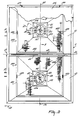
- Figure 1 is a front view of a spreader;
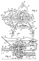
- Figure 2 is a side view of the spreader of Figure 1, taken in the direction of the arrow in Figure 1;
- Figure 3 is a plan view of the spreader of Figures 1 and 2, taken in the direction of the arrow III in Figure 2;
- Figure 4 is a fragmentary plan view of part of the spreader taken on the line IV-IV in Figure 1;
- Figure 5 is a sectional view taken on the line V-V in Figure 3;
- Figure 6 is a sectional view taken on the line VI-VI in Figure 1;
- Figure 7 is a sectional view taken on the line VII-VII in Figure 6;
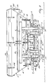
- Figure 8 is a front view of another spreader;
- Figure 9 is a hydraulic circuit diagram representing the drive circuit of the spreader shown in Figure 8;
- Figure 10 corresponds to Figure 9, but represents an alternative drive circuit; and
- Figure 11 is a fragmentary sectional view of drive means for a spreader similar to that of Figure 8.
- Referring to Figures 1 to 7, the spreader comprises a frame 1 on which a
hopper 2 anddistribution members 3 and 4 are arranged. The frame 1 comprises an upwardly extendingframework 5 having uprighthollow beams 6 and 7 of rectangular cross-section. To the top ends of thebeams 6 and 7 is secured a horizontal supportingbeam 8 of rectangular cross-section. The distance 9 between thebeams 6 and 7 is smaller than the length 10 of thebeam 8. Thebeam 8 projects equally at each end beyond the beams 6 and 7 (Figure 1). The distance 9 is smaller than half the width 11 of thehopper 2 and the length 10 of thebeam 8 is greater than half the width 11. - The
beams 6 and 7 are provided withtags 12 for attachment to the lower lifting arms of a three-point lifting device of a tractor or a similar vehicle to which the spreader is to be hitched. Thebeam 8 is provided withtags 13, which can be coupled with the top lifting arm of the three-point lifting device. - At a position near their lower ends, the
beams 6 and 7 are interconnected by a lower beam 14, also of rectangular cross-section. As can be seen in Figure 4, the beam 14 hasfront parts beams 6 and 7 towards the rear and meet substantially parallelrear parts 17 and 18, which are interconnected by abend 19. At thebend 19, adrawhook 20 is fastened to the beam 14, thisdrawhook 20 comprising two strips located one above the other. Near ends of the beam 14 thefront parts tie beam 21, which also has a rectangular cross-section, as is shown in Figure 2. Supportingbeams beams 6 and 7 at a short distance above their mid-points. Thebeams beams 6 and 7 and converge in the same manner as thefront parts rear parts beams parts 17 and 18 of the beam 14. The connection of the supportingbeams beams 6 and 7 is reinforced bystruts beams beams coupling strips struts beams distance 30 from thebeams 6 and 7. Viewed on plan (Figure 4) the connectingstrips strips strips beams 6 and 7 and are at right angles to thebeams strips rear edges 32 are bent towards one another and towards the centre of the spreader in order to stiffen thestrips beams 6 and 7 are provided with supportingfeet 33 and the rear end of the lower beam 14 has a supportingfoot 34. Thebeams framework 5 and are horizontal in the upright position of the spreader. - The
hopper 2 comprises two funnel-shaped delivery parts 41 and 42, thejunction 43 of the adjoining walls of the delivery parts being located at a height 44 above the hopper bottom. The height 44 is slightly greater than theheight 45 of the hopper. At the front, thehopper 2 has a fastening beam 46, which is fastened by bolts to a fastening plate 47. The plate 47 is rigidly secured to the horizontal supportingbeam 8. The fastening plate 47 projects to the rear from thebeam 8 and it is this projecting part which provides support for the beam 46. The top of the beam 46 is located at the same level as the junction 43 (see Figure 2). The front and rear walls of the hopper are interconnected above thejunction 43 by astiffening strip 48. Thelower edge 49 of thestrip 48 is bent over laterally and thetop rim 50 thereof is bent over through about 180° (Figure 1). - The
delivery parts 41 and 42 are provided with delivery spouts 51 and 52 respectively, which are independent of the rest of the hopper and which each have twooutlet orifices 53 and 54. The outlet orifices 53 and 54 are provided in the bottom 59 of the delivery spouts 51 and 52 respectively. The hopper with the delivery spouts 51 and 52 and theorifices 53 and 54 therein is symmetrical about a plane of symmetry 55 going through the longitudinal centre line of the spreader. The frame is also symmetrical about the plane 55. One edge of each orifice 54 is located approximately in avertical plane 56, which is parallel to the plane of symmetry 55 and goes through the centre of therespective delivery spout planes 56. Theorifices 53 are located on the outboard sides of theplanes 56 and eachorifice 53 is off-set about an angle of about 30° with respect to theplane 56 around the vertical centre line 115 (Figure 5) of therespective delivery part 41 or 42 and of theround bottom plate 59. Theorifices 53 and 54 are each located in front of a plane 60 extending transverse of the intendeddirection 58 of operative travel of the spreader and going through the centre lines 115. Theorifices 53 and 54 are located near the front edge of thebottom plate 59, as viewed in thedirection 58. - The
spouts plate 61, which is fastened, for example welded, to the spouts at aheight 62 above the underside of thebottom plate 59. The supportingplate 61 bears on the top sides of the supportingbeams parallel parts parallel parts plate 61 is fastened to each of theparts bolts 63, for which purpose thebeams holes 64 for receiving thebolts 63. - The supporting
plate 61 supports thedistribution members 3 and 4 with their driving means on the supportingbeams distribution members 3 and 4 are mounted on acommon carrier 70. Thecarrier 70 comprises acentral casing 71 on each side of which are mounted hollowshaft carrying members 72. The ends of the carryingmembers 72 away from thecentral casing 71 are provided withgear boxes 73 in whichshafts 66 and thedistribution members 3 and 4 are journalled. To the rear side of thecentral casing 71 with respect to thedirection 58 is fastened a change-speed box 74. In thecasing 71 is journalled acoupling shaft 75, thefront end 76 of which emerges from the front of the casing and the rear end 77 of which extends into thebox 74. The shaft end 77 is provided with agear wheel 78 which co-operates with agear wheel 79 on ashaft 80. Theshaft 80 is journalled in thecentral casing 71 perpendicularly beneath theshaft 75, the centre lines of theshafts casing 71 theshaft 80 is provided with abevel gear wheel 81, which co-operates with abevel gear wheel 82 on a drivingshaft 83. Theshaft 83 extends across thecentral casing 71 and the carryingmembers 72, the end of theshaft 83 extending into thegear boxes 73. The ends of theshaft 83 located in thegear boxes 73 are provided withbevel gear wheels 84 cooperating withbevel gear wheels 85 arranged on theshafts 66. In Figure 5 it can be seen that thegear boxes 73 are provided on their outboard sides withextensions 86 havingfiller caps 87. - The
box 74 is provided with aclosing cover 88, which is secured to thebox 74 by two releasable fastening knobs 89 (only one is visible in Figure 2). - On both sides of the
central casing 71 the carryingmembers 72 are provided with supports 91 which protrude, as viewed in thedirection 58, in front of and behind the carryingmembers 72 extending transversely of thedirection 58. The supports 91 are connected to thecarrier 70 by welding. The supports 91 connect thecarrier 70 to twobrackets 92 welded to the underside of strip- shapedintermediate pieces 93. As will be seen in Figure 4, thestrips 93 are V-shaped and are fastened to the underside of afastening plate 94. Thefastening plate 94 is secured bybolts 95 to the supportingplate 61. Thebolts 95 are located above the bolts 90. Theplate 94 covers substantially the whole distance between the supportingbeams bolts 95 are located close to the parallel ends 24, 25 of the supportingbeams - The
coupling part 76 of theshaft 75 protruding from the front of thecasing 71 is journalled in abearing 96 of thecasing 71, about which casing aprotective plate 97 is arranged, which flares forwardly. - The
distribution members 3 and 4 are identical and therefore only the distribution member 3 will be described in detail. Thedistribution members 3 and 4 are symmetrical in shape with respect to theplane 56. The distribution member 3 comprises a circular plate 101, thecentral part 102 of which is raised and has a flatcentral part 103 and a conical rim 104. Thecentral part 102 has a diameter 105, which is slightly larger than one third and smaller than half the diameter 106 of the plate 101. From thecentral part 102 the plate 101 has asurface 108 which flares upwardly at an angle 107 of about 6°. At the outer edge of the plate 101 there is a downwardly bent-overrim 109. In this embodiment four ejection blades 110 are arranged on thepart 108. The blades 110 are each disposed in a trailing position with respect to the intended direction of rotation 112. The inner ends 111 lead with respect to theends 113 by an angle 114 of about 15°. - The plate 101 of the
distribution member 113 is secured to a fastening plate 116 welded to theshaft 66. Ther blades 110 extend, as will be apparent from Figure 4, from theouter edge 109 to near the circumference of thecentral part 102. - In each
delivery spout bottom plate 59, there is anagitator 122 as shown in Figure 5 for thedelivery spout 51. Thebottom plate 59 of thespout 56 has anorifice 120. Theshaft 66 extends up to theorifice 120 and is provided with ahub 121 which extends through theorifice 120 into the lower end of thedelivery spout 56. Thehub 121 forms part of theagitator 122, which comprises aring 123 concentric with thehub 121. Thering 123 is coupled by two aligned spokes 124 with thehub 121. The spokes 124 haveparts 125 which are slightly inclined upwardly away from the hub and have at the ends downwardly bent end parts 126, which are connected with thering 123. -
Dosing members 129 and 130 cooperate with the delivery spouts 51 and 52. Thedosing members 129 and 130 are identical and arranged symmetrically in shape with respect to the plane 55. The two dosing members are mounted in an identical manner beneath the delivery spouts concerned, and consequently only thedosing member 129 will be described in detail (Figure 5). Thedosing member 129 comprises a ring located beneath thebottom plate 59 and bearing on a supporting ring 131, which is fastened by bolts 132 beneath the bottom plate. Between the ring 131 and thebottom plate 59 is arranged aspacer ring 133 in a manner such that that a groove is left between the outer periphery of thering 133 and the supporting ring 131 for rotatably holding the inner rim of thedosing ring 129. Thedosing ring 129 is rotatable about the outer periphery of thering 133 and about therotary shaft 115. Thedosing ring 129 has two passage openings 134. These openings 134 are arranged around theshaft 66 in the same manner as theorifices 53 and 54. Thedosing ring 129 is provided with aflaring collar 135, to which is pivoted arod 136, which is pivotally coupled with acontrol arm 137 rigidly secured to acontrol shaft 138. In the same manner the dosing ring 130 is pivotally coupled by means of arod 139 with a control arm 140, which corresponds with thearm 137 and is also fastened to thecontrol shaft 138. - The diameter of the
opening 120 is larger than the outer diameter of thehub 121. Theopening 120 is sealed by a sealing ring 141 of slightly flexible material having a radial flange 142 on the underside. The flange 142 is held between thebottom plate 59 and the supporting ring 131. The inner diameter of thespacer ring 133 is greater than the inner diameter of the ring 131 and than the diameter of theopening 120. The ring 141 extends axially along thehub 121 through theopening 120 as far as a position above thebottom plate 59 in the hopper. - Around the inboard sides of the
distribution members 3 and 4 are arrangedprotective hoods 145. Thehoods 145 are arranged symmetrically with respect to the vertical plane 55 and have symmetrical shapes; as will be seen from Figure 4, they have an angular cross-section with a horizontal side 146 and a vertical side 147. The lower edge of the side 147 is located at a lower level than the top edge of therim 109 of the plate 101 of the distribution member concerned. Theprotective hoods 145 are fastened to the underside of the supportingbeams bolts 63, by which thesupport 61 is secured to the top of the supportingbeams - The
control shaft 138 is arranged in front of thedelivery parts 41 and 42 of the hopper and is rotatably journalled instrips 150 and 151 fastened to the hopper. Thecontrol shaft 138 extends, as seen from the front, over a length substantially equal to the width of the hopper at the level of the control shaft 138 (Figure 1). Thestrip 151 is provided with a settingmember 152 comprising a plate 153 fastened to thestrip 151 and having the shape of a sector and being provided at its outer periphery with anarcuate plate 154 centred on the axis of thecontrol shaft 138. Theplate 154 is located at a short distance from the plate 153 and is coupled at its ends with the plate 153 so that a slot is left between theplates 153 and 154. This slot accommodates an adjusting arm 155, which is fixedly coupled with thecontrol shaft 138. Theplate 153 and 154 have registering holes 156. Astop 157 formed by a pin can be passed at will through a pair of registering holes 156. - Near the plane 55 the
control shaft 138 is provided with alignedarms 160 and 161. Thearms 160 and 161 are coupled with hydraulically controlledcontrol arms 162 and 163 bearing on asupport 164, which is arranged on the supportingplate 61. Thearms 162 and 163 are hydraulically controllable in a manner such that their length is variable. The hydraulicallycontrollable arms 162 and 163 are coupled by means ofhoses 165 with a hydraulic control mechanism of a vehicle to which the spreader is hitched. - On the left-hand side, viewed with respect to the
direction 58, the hopper has fastened to it arockable indicating member 168. This indicating member comprises a pointer 170, which is freely rotatable about a pin 169. The pin 169 is fastened to a support 171 arranged on the side wall of the hopper. Near the end of the pointer 170 abracket 172 is fastened to the hopper. Thebracket 172 is provided with ascale 173. The pointer 170 is retained on the shaft 169 by a wing-nut 174. - The hopper is provided on the top with a
canvas cover 176. Thecanvas cover 176 is fastened by means ofelastic tapes 177 tohooks 178 provided on the hopper. At the top the funnel-shapeddelivery parts 41 and 42 tapering downwards have twosieves 180. Thesesieves 180 each have a rectangular frame 181 enclosing a more or lessfine mesh 182. The frame 181 is provided withhandles 183. The frame 181 of each sieve is such that this frame bears on the upper regions of the walls of thedelivery parts 41 and 42. Thesieves 180 are located in the upper region of eachdelivery spout 41 and 42 one on each side of thejunction 43. - For operation the spreader is hitched to the three-point lifting device of a tractor or a similar vehicle, the lower fastening strips 12 being coupled with the lower arms and the fastening strips 13 with the top arm of the three-point lifting device. The
front end 76 of thecoupling shaft 75 is connected through an auxiliary shaft with the power take-off shaft of the tractor. - The material to be spread is put into the hopper. If desired, the
sieves 180 are fitted before filling in order to prevent large lumps of material from getting into thedelivery parts 41 and 42. - After the hopper is filled, it can be covered by the
cover 176 if it is desired with regard to weather conditions, to avoid wetting of the material and its escape from the hopper, for example by wind action. - For spreading the material, it is fed from the hopper to the
distribution members 3 and 4. In order to spread the material in a desired manner the spreader must be suitably positioned by the lifting device above the surface to be covered. Usually the spreader is arranged so that thedistribution members 3 and 4 are parallel to the surface to be covered. The orientation of the spreader can be checked by means of the indicatingdevice 168. thedistribution members 3 and 4 will be horizontal when the pointer 170 coincides with the extreme right-hand part of thescale 173 as shown in Figure 2. It may be desirable under some conditions to dispose thedistribution members 3 and 4 such that they are inclined upwardly from front to rear. This can be achieved by changing the length of the top rod of the three-point lift, which is coupled with thestrips 13. The inclined position of the spreader can be read from the position of the indicator 170 with repect to thescale 173 and thebracket 172. The inclined position of the distribution members may be used for ejecting the material obliquely upwards so that it can be spread over a large distance. This position may, moreover, be used for spreading material on standing crop. If desired, the spreader can be inclined downwardly from front to rear. This may be important for spreading material down into standing crop. For this purpose thescale 173 can be extended to the right (Figure 2). When the spreader is arranged in the desired position, the material can be spread by feeding it from the hopper to the distribution members during the travel of the spreader. For spreading, thedistribution members 3 and 4 are rotated, for example, from the power take-off shaft through theshaft 75. The distribution members are thus rotated in the direction of the arrow 112, the outboard sides of thedistribution member 3 and 4 thus moving rearwards with respectto thedirection 58 and thus in the direction in which the material is mainly spread. The driving effort is transferred from theshaft 75 through thegear wheels shaft 80. Theshaft 80 drives through thewheels shaft 83, which, in turn, drives theshaft 66 of the distribution members through thewheels wheels shafts - The amount of material flowing per unit time from the hopper can be controlled by closing the
outlet ports 53 and 54 to a greater or lesser extent by means of thedosing members 129 and 130 respectively. When setting the dosing members the outlet ports 134 will coincide to a greater or lesser extent with theoutlet ports 53 and 54. The position of thedosing members 129 and 130 can be adjusted by means of the adjusting mechanism comprising the settingmember 152 and thecontrol shaft 138 with thecontrol arms 162 and 163. The ports 134 will be located entirelyto one side of theports 53 and 54, when the control arm 155 is located near the lower end of theplates 153 and 154. The adjusting arm 155 then bears on the junction between theplates 153 and 154, which junction thus constitutes a stop. In the completely open position in which the ports 134 register fully with theports 53 and 54, the adjusting arm 155 is located near the other end of theplate 154. An intermediate position can be determined by means of thepin 157, which can limit the upwards movement of the adjusting arm 155 and which can thus be used to determine the extent of overlap of the ports 134 with theports 53 and 54for adjusting the free passage of theoutlet ports 53 and 54. - The adjustment of the
dosing members 129 and 130 with respect to the delivery spouts 51 and 52 and hence with respect to theoutlet ports 53 and 54 is preferably performed from the vehicle carrying the device. - In this embodiment the
dosing members 129 and 130 can be hydraulically controlled from the tractor. For this purpose the lengths of thecontrol arms 162 and 163 can be varied through theduct 165 and a corresponding duct coupled with the hydraulically controlledarm 163. When oil is fed to the arm 162, it will be lengthened so that the distance between thesupport 164 and thearm 160 is enlarged and thecontrol arm 160 will turn to the left as seen in Figure 2. As a result the adjusting arm 155 will move towards the lower edge of theplate 154 until it reaches the zero position. In moving to this position thecontrol shaft 138, acting through thearms 137 and 140 respectively and therods dosing members 129 and 130 respectively so that theoutlet ports 133 and 134 are located entirely to the side of theports 53 and 54 so that no material can pass from the hopper to the distribution members. By removing the pressure in theduct 165 and by raising the pressure in the duct coupled with thearm 163 the distance between the arm 161 and thesupport 164 will increase by the increase in length of thearm 163. Thus thecontrol shaft 138 will turn clockwise as seen in Figure 2. The adjusting arm 155 is thus moved upwardly up to thestop 157, which determines the extent of maximum overlap of the ports 134 and theports 53 and 54. - Although in this embodiment the
arms 162 and 163 are hydraulically controllable, they may, as an alternative, be constructed so as to be mechanically controllable. - The
pin 157 can be readily inserted into any registering pair of holes 156 by positioning the adjustingmember 152 near the side of the hopper. The positions of thecontrol arm 138 and of the adjustingmember 152 at the front of the hopper provide the advantage that the adjusting mechanism cannot be soiled by material ejected by thedistribution members 3 and 4 so that the adjusting mechanism remains readily controllable and can be easily kept in good condition. The location of thearms 162 and 163 nearthe middle of the machine and the coupling with thecontrol arm 138 at the centre facilitate the turn of the control arm and provide an advantageous mode of connection of the control members with the tractor. - The shape of the frame of the spreader and the connection of the hopper to it allow ready access to all parts of the spreader, whilst the frame can be easily manufactured and the various parts can be readily mounted thereon. In the construction shown the driving members for the
distribution members 3 and 4 can also be reaily mounted. - The
distribution members 3 and 4 with thecarrier 70 and thecasing intermediate pieces 93 and theplate 94 to the supportingplate 61. Thedistribution members 3 and 4 are coupled by theplate 61 to the delivery spouts 51 and 52 and together they are arranged on the supportingbeams distribution members 3 and 4 with the supporting plate 61 a fixed position of thedistribution members 3 and 4 relative to the delivery spouts 51 and 52 and therewith to the hopper is ensured. Therefore, thedistribution members 3 and 4 are constantly held in the correct position in which they are disposed during mounting with respect to theoutlet ports 53 and 54. Thus the material can always flow in the desired manner to the distribution members from the hopper so that it can be spread in the desired direction. - When the
carrier 70 with thedistribution members 3 and 4 is mounted on the supportingplate 61, the position of thedistribution members 3 and 4 relative to the underside of the delivery spouts 51 and 52 can be adjusted. Moreover, thedistance 62 can be adjusted to the desired value during this mounting operation. If desired, the delivery spouts 51 and 52 can be fixedly coupled with the rest of thedelivery parts 41 and 42, for example, by welding. The weight of the hopper is supported by the beam 46 and the supportingplate 61 on the frame. If the spreader with the completely filled hopper travels across an uneven surface, various parts of the frame may bend slightly, but even with the slightest flexure the position of thedistribution members 3 and 4 relative to the hopper will not change, since thesedistribution members 3 and 4 are connected to the hopper by the supportingplate 61 and not by the frame. The hopper and hence thedistribution members 3 and 4 can constantly be held in the desired position, since the indicatingmember 168 mounted on the hopper displays the orientation of the hopper and thedistribution members 3 and 4. - The position of the
ports 53 and 54 around therotary shafts 115 of thedistribution members 3 and 4 is chosen so that the material is supplied at the desired place to the distribution members for spreading it in the desired direction. Thus, the position indicated for theoutlet ports 53 and 54 with respect to theplane 56 is important. - In this embodiment the
ports 53 and 54 are positioned so that thedistribution members 3 and 4 both spread the material over coinciding sectors. Owing to the symmetrical disposition of thedelivery parts 41 and 42 with their outlet ports and to the symmetrical disposition of thedistribution members 3 and 4 with respect to the plane 55, and owing to their direction of rotation, the sectors covered by the material will be symmetrical about the plane 55. During operation of the spreader each of the distribution members will spread the material over substantially the whole width of the strip to be covered so that a very uniform distribution of the material on the strip is obtained. - A satisfactory flow of material through the outlet ports is ensured by the
agitators 122 and the delivery spouts 51 and 52 of the hopper. These agitators have a shape such that the material is kept moving above the outlet ports without being comminuted or compressed in an undesirble manner. Theagitators 122 can be readily mounted on theshafts 66, since theopenings 120 in thebottom plates 59 of the hopper parts are large compared to the diameter of thehubs 121. A satisfactory seal of theopenings 120 is obtained by means of the sealing rings 141, which can be readily arranged between thebottom plate 59 and the supporting ring 131. Theprotective hoods 145 are located outside the sectors to be covered by the material ejected by the distribution members and they serve to screen parts of the machine from scattered material. The shape of thedistribution members 3 and 4 shown enables to obtain a uniform distribution of the material over the spreading sector of each distribution member, whilst the material can be ejected over a comparatively large distance by each of the distribution members in dependence on the speed of rotation of the distribution members. Owing to the shape of the distribution members the material emanating from theoutlet ports 53 and 54 will readily flow over the conical surface 104 of thecentral part 102 towards the spreading arms 110, which can readily capture the material by their inner ends 111 from thecentral part 102. Owing to their shape the distribution members can be readily manufactured. - Figures 8 and 9 show an embodiment in which the spreader is largely identical to that shown in the preceding Figures, but the drive of the
distribution members 3 and 4 differs. Corresponding parts of the spreader shown in Figures 8 and 9 are designated by the same reference numerals as those parts in Figures 1 to 7. In this embodiment thedistribution members 3 and 4 are arranged on a carrier 186 having supports 187. To the supports 187 is fastened aplate 188, which is secured by means of intermediate pieces formed by strips 189, which correspond with thestrips 93, to theplate 94. Theplate 94, and consequently the carrier 186, is fastened to the supportingplate 61 as before. The carrier 186 comprises a hollow carrying member 190, at the ends of whichgear boxes 191 and 192 are provided below thedistribution members 3 and 4. Through the carrying member 190 extends a drivingshaft 193, which is coupled at the wheel joining thebox 192 throughgear wheels 194 with theshaft 195 of thedistribution member 4. In the box 191 theshaft 193 is coupled throughgear wheels 196 with theshaft 197 of the distribution member 3. To the box 191 is fastened ahydraulic motor 198, which is coupled with theshaft 193. Themotor 198 communicates by means of aline 199 with the hydraulic driving system of a vehicle, for example, a tractor carrying the spreader. - As in the preceding embodiment, the
distribution members 3 and 4 with their drive are carried entirely by the supportingplate 61 which supports them, together with thespouts beams shaft 195 is provided with a connectingmember 200 for a revolution counter to indicate the speed of rotation of theshaft 195. Theshafts shaft 193 is driven by themotor 198. During operation of the spreader of Figure 8 the motor can be driven from the hydraulic system of the tractor. The revolution counter with thecoupling member 200 helps in keeping the desired speed of thedistribution members 3 and 4 constant and enables a constant check to be made. If desired, the drive of themotor 198 from the hydraulic system of the tractor can be rendered adjustable for this purpose. A spreader in which the distribution members are coupled with a hydraulic motor, whereby two distribution members are drivingly intercoupled with each other forms the subject-matter of the European patent application 84200728.8, published as EP-A-0125740. - Figure 9 illustrates schematically the drive circuit of the
motor 198. Themotor 198 is coupled through theduct 199 with thepump 209 of the tractor. The device comprises a control-valve 201 arranged in thesupply line 199 to themotor 198 for controlling the speed of rotation of themotor 198. The tractor carrying the spreader will comprise a control valve for closing or opening respectively the feed from thepump 209 to theline 199 and themotor 198. Between thesupply line 199 and thereturn line 202 is arranged anoverflow valve 203 associated with the spreader and themotor 198. When the flow from thepump 209 to themotor 198 is cut off the motor will have a certain momentum. In order to avoid themotor 198 stopping too abruptly when the flow from thepump 209 to the motor is cut off, theoverflow device 203 is provided. The momentum of themotor 198 is capable of maintaining the circulation of the oil contained in the pump and in parts of theducts overflow 203 until the momentum is dissipated and themotor 198 and hence thedistribution members 3 and 4 come to a standstill. - Figure 10 is a circuit diagram in which the motor corresponding with the
motor 198 is avariable motor 204 having, for example, an adjustable swash plate. The adjustment of themotor 204 can be used for increasing the starting torque of the motor to put the drive with thedistribution members 3 and 4 into motion. As in the preceding embodiment of Figure 9 thecontrol valve 201 can be set to a desired value. Particularly in the case of lower power and a high speed of the motor during normal operation it may be advantageous to have a possibility of manually controlling themotor 204 in order to increase the starting torque. - Figure 11 schematically shows a construction in which between a hydraulic motor, for example, the
motor shaft 193 is arranged a set ofgear wheels gear wheels speed box 207. Thegear wheels motor 198 and thegear wheels distribution members 3 and 4 can be driven with speeds varying between 250 and 500 rev/min. Thegear wheels gear wheel 205 can be directly coupled with theshaft 193 and thegear wheel 206 with themotor 198. The combination of gear wheels is chosen so that in this second position thedistribution members 3 and 4 can be driven over a range of speeds lying between 500 and 1000 rev/min. In order to facilitate the interchange of thegear wheels box 207 is provided in a manner not shown with a readilyremovable cover 208.
Claims (34)
Priority Applications (1)
| Application Number | Priority Date | Filing Date | Title |
|---|---|---|---|
| AT81201291T ATE18623T1 (en) | 1980-11-27 | 1981-11-23 | SPREADER. |
Applications Claiming Priority (2)
| Application Number | Priority Date | Filing Date | Title |
|---|---|---|---|
| NL8006454 | 1980-11-27 | ||
| NL8006454A NL8006454A (en) | 1980-11-27 | 1980-11-27 | DEVICE FOR SPREADING GRAIN AND / OR POWDER MATERIAL. |
Related Child Applications (1)
| Application Number | Title | Priority Date | Filing Date |
|---|---|---|---|
| EP84200728.8 Division-Into | 1984-05-18 |
Publications (3)
| Publication Number | Publication Date |
|---|---|
| EP0053419A1 EP0053419A1 (en) | 1982-06-09 |
| EP0053419B1 EP0053419B1 (en) | 1986-03-19 |
| EP0053419B2 true EP0053419B2 (en) | 1991-01-16 |
Family
ID=19836247
Family Applications (2)
| Application Number | Title | Priority Date | Filing Date |
|---|---|---|---|
| EP81201291A Expired - Lifetime EP0053419B2 (en) | 1980-11-27 | 1981-11-23 | A spreader |
| EP84200728A Withdrawn EP0125740A1 (en) | 1980-11-27 | 1981-11-23 | A spreader |
Family Applications After (1)
| Application Number | Title | Priority Date | Filing Date |
|---|---|---|---|
| EP84200728A Withdrawn EP0125740A1 (en) | 1980-11-27 | 1981-11-23 | A spreader |
Country Status (5)
| Country | Link |
|---|---|
| US (2) | US5046664A (en) |
| EP (2) | EP0053419B2 (en) |
| AT (1) | ATE18623T1 (en) |
| DE (1) | DE3174144D1 (en) |
| NL (1) | NL8006454A (en) |
Families Citing this family (37)
| Publication number | Priority date | Publication date | Assignee | Title |
|---|---|---|---|---|
| EP0088105B1 (en) * | 1981-09-14 | 1986-07-30 | C. van der Lely N.V. | Device for spreading granular and/or powdery material |
| NL8200562A (en) * | 1982-02-15 | 1983-09-01 | Lely Nv C Van Der | DEVICE FOR SPREADING GRAIN AND / OR POWDER MATERIAL. |
| DE3310694A1 (en) * | 1983-03-24 | 1984-09-27 | Amazonen Werke Dreyer H | Centrifugal distributor, especially for the output of mineral materials for distribution |
| DE3739265A1 (en) * | 1987-11-20 | 1989-06-01 | Amazonen Werke Dreyer H | Broadcaster |
| EP0570633B1 (en) * | 1991-09-05 | 1998-11-25 | Intech Exports | Electrostatic powder coating |
| DE9306605U1 (en) * | 1993-05-03 | 1994-09-15 | Amazonen Werke Dreyer H | Border spreading screen and centrifugal spreader equipped with it |
| NL9500565A (en) * | 1994-07-22 | 1996-03-01 | Maasland Nv | Device for spreading granular and / or powdery material. |
| US5820035A (en) * | 1996-04-04 | 1998-10-13 | Johnson; John B. | Broadcast spreader mechanism |
| US6047909A (en) * | 1996-11-25 | 2000-04-11 | White Castle System, Inc. | Hopper discharge and pattern controlling apparatus for a broadcast spreader |
| DE19929356C2 (en) * | 1998-07-09 | 2003-10-09 | Rauch Landmaschfab Gmbh | Broadcaster |
| US6149079A (en) | 1998-09-03 | 2000-11-21 | Turfco Manufacturing, Incorporated | Broadcast spreading top dresser |
| US7540436B2 (en) * | 1999-03-09 | 2009-06-02 | Charles J Truan | Truck bed mounted spreader |
| US6953163B2 (en) * | 1999-03-09 | 2005-10-11 | Trynex, Inc. | Truck bed mounted spreader |
| US6209808B1 (en) | 2000-01-07 | 2001-04-03 | Gvm, Incorporated | Spreader attachment |
| US6517281B1 (en) | 2000-05-19 | 2003-02-11 | Highway Equipment Company | Adjustable spinner for a particulate material spreader |
| US6817552B2 (en) | 2002-02-06 | 2004-11-16 | Turfco Manufacturing, Inc. | Broadcast spreading top dresser |
| US6547169B1 (en) | 2002-06-25 | 2003-04-15 | Case Corporation | Crop residue spreader for an agricultural combine |
| US6910646B2 (en) * | 2003-01-31 | 2005-06-28 | Jeffrey H. Vernon | Aggregate spreader and methods of use |
| US7347320B2 (en) * | 2004-04-28 | 2008-03-25 | Turfco Manufacturing, Inc. | Top dresser |
| DE502007000081D1 (en) * | 2006-02-24 | 2008-10-09 | Roegelberg Holding Gmbh & Co K | Verstellgetriebeanordnung especially for fertilizer control |
| DE102006019477A1 (en) * | 2006-04-26 | 2007-10-31 | Amazonen-Werke H. Dreyer Gmbh & Co. Kg | Device for sprinkling granular substances |
| DE102007011859A1 (en) | 2007-03-05 | 2008-09-11 | Adolf Würth GmbH & Co. KG | container |
| US8757521B2 (en) | 2008-05-09 | 2014-06-24 | Oms Investments, Inc. | Cartridge spreader system |
| DE202009010907U1 (en) * | 2009-03-26 | 2009-11-19 | Deere & Company, Moline | Harvest crop shred and distribution arrangement for a combine harvester |
| KR101140657B1 (en) * | 2009-07-31 | 2012-07-12 | 김완수 | non-power double spray fan and fertilizer spreader are that its characteristics are pulled by wheel drive |
| KR20110027052A (en) * | 2009-09-09 | 2011-03-16 | 김완수 | Fertilizer scattering spreadr having duplex exhaust hole |
| US8814012B2 (en) * | 2010-02-26 | 2014-08-26 | Mt. Carmel Stabilization Group, Inc. | Material spreader for use with an excavator |
| US8800896B1 (en) * | 2011-10-20 | 2014-08-12 | Johnny L. Hinton | Motorized spreader assembly |
| USD668692S1 (en) * | 2012-04-25 | 2012-10-09 | Noon Lawn & Landscape Co., Inc. | Spreader carrier |
| US9763384B2 (en) | 2012-09-14 | 2017-09-19 | Cnh Industrial America Llc | Motor control system and method for agricultural spreader |
| US9491902B1 (en) | 2013-02-06 | 2016-11-15 | Turfco Manufacturing, Inc. | Broadcast spreading top dresser for sand |
| CN107404837B (en) * | 2014-12-30 | 2021-09-21 | 马斯奇奥-盖斯帕多集团 | Centrifugal spreader for fertilizer |
| USD787564S1 (en) * | 2015-04-17 | 2017-05-23 | Kinze Manufacturing, Inc. | Toolbar with wheel arches |
| USD780230S1 (en) * | 2015-04-17 | 2017-02-28 | Kinze Manufacturing, Inc. | Saddle fertilizer tank holder |
| DE102016002827A1 (en) * | 2016-03-09 | 2017-09-14 | Rauch Landmaschinenfabrik Gmbh | distributing |
| US10582656B2 (en) | 2016-09-09 | 2020-03-10 | Perma-Green Supreme, Inc. | Agitation units and systems, and dispensing equipment equipped therewith |
| USD860261S1 (en) | 2017-02-24 | 2019-09-17 | Oms Investments, Inc. | Spreader |
Family Cites Families (31)
| Publication number | Priority date | Publication date | Assignee | Title |
|---|---|---|---|---|
| FR391691A (en) * | 1908-06-25 | 1908-11-06 | Charles Louis Auguste Severin | Centrifugal seed drill |
| US1776814A (en) * | 1929-09-26 | 1930-09-30 | Wilmer A Lutz | Lime spreader |
| US2594084A (en) * | 1946-04-29 | 1952-04-22 | Skibbe Henry | Seed and fertilizer spreader |
| US2537913A (en) * | 1947-10-06 | 1951-01-09 | Rimple Mfg Co | Material distributor |
| GB733935A (en) * | 1952-11-17 | 1955-07-20 | William Edmund Lea | Improvements in or relating to mechanical spreaders and distributors |
| GB854051A (en) * | 1955-12-08 | 1960-11-16 | Massey Ferguson Ltd | Improvements in centrifugal distributors for granular fertilizers and like discrete substances |
| US3167319A (en) * | 1961-05-16 | 1965-01-26 | Torrey Anthony J | Sand spreading mechanism with reversible conveyor |
| DE1457769A1 (en) * | 1965-04-29 | 1969-05-29 | Amazonen Werke Dreyer H | Centrifugal spreaders, in particular for spreading mineral fertilizers |
| NL6610826A (en) * | 1965-08-11 | 1967-02-13 | ||
| US3313549A (en) * | 1965-09-03 | 1967-04-11 | Willmar Mfg | Compact spreader for particulate |
| NL6717659A (en) * | 1967-12-27 | 1969-07-01 | ||
| US3539113A (en) * | 1968-07-09 | 1970-11-10 | Letco Inc | Distributor means for a fertilizer spreader |
| NL161969C (en) * | 1968-09-09 | 1980-04-15 | Lely Nv C Van Der | DEVICE FOR SPREADING GRAIN AND / OR POWDER MATERIAL. |
| US3899138A (en) * | 1969-01-17 | 1975-08-12 | Der Lely Ary Van | Spreading implements |
| NL6902712A (en) * | 1969-02-21 | 1970-08-25 | ||
| US3559893A (en) * | 1969-05-21 | 1971-02-02 | Swenson Spreader & Mfg Co | Material distributing apparatus |
| BE755901A (en) * | 1969-09-12 | 1971-02-15 | Lely Nv C Van Der | DEVICE FOR SPREADING MATERIAL |
| US3815824A (en) * | 1972-12-29 | 1974-06-11 | Olson E Inc | Sand spreader |
| FR2229574B1 (en) * | 1973-05-17 | 1977-01-07 | Burel Sa Ets F | |
| DE2439046C2 (en) * | 1974-08-14 | 1984-04-05 | Robert Bosch Gmbh, 7000 Stuttgart | Device for distributing grit |
| US3904129A (en) * | 1974-09-16 | 1975-09-09 | Highway Equip Co | Hydraulic system for vehicular spreader |
| JPS5247185A (en) * | 1975-10-14 | 1977-04-14 | Nissan Motor Co Ltd | Speed controller of travelling liquid actuator |
| NL7613260A (en) * | 1976-11-29 | 1978-05-31 | Texas Industries Inc | DEVICE FOR DISTRIBUTION OF GRAIN AND / OR POWDER MATERIAL. |
| US4098433A (en) * | 1977-02-09 | 1978-07-04 | Dickey-John Corporation | Hydraulic system for broadcast spreader |
| NL190570C (en) * | 1978-05-05 | 1994-05-02 | Lely Nv C Van Der | Device for spreading granular and / or powdery material. |
| NL190569C (en) * | 1978-05-05 | 1994-05-02 | Lely Nv C Van Der | Device for spreading granular and / or powdery material. |
| DE2835011C2 (en) * | 1978-08-10 | 1980-10-02 | Amazonen-Werke H. Dreyer Gmbh & Co Kg, 4507 Hasbergen | Centrifugal spreaders, especially for granular fertilizers |
| NL7810805A (en) * | 1978-10-31 | 1980-05-02 | Lely Nv C Van Der | DEVICE FOR SPREADING GRAIN AND / OR POWDER MATERIAL. |
| NL8006604A (en) * | 1980-01-16 | 1981-08-17 | Lely Nv C Van Der | DEVICE EQUIPPED WITH A RESERVOIR FROM WHICH MATERIAL CAN BE DRAINED. |
| DE3018792C2 (en) * | 1980-05-16 | 1983-03-31 | Danfoss A/S, 6430 Nordborg | Hydrostatic control device, in particular steering device |
| NL8200177A (en) * | 1982-01-19 | 1983-08-16 | Lely Nv C Van Der | DEVICE FOR SPREADING GRAIN AND / OR POWDER MATERIAL. |
-
1980
- 1980-11-27 NL NL8006454A patent/NL8006454A/en not_active Application Discontinuation
-
1981
- 1981-11-23 DE DE8181201291T patent/DE3174144D1/en not_active Expired
- 1981-11-23 EP EP81201291A patent/EP0053419B2/en not_active Expired - Lifetime
- 1981-11-23 EP EP84200728A patent/EP0125740A1/en not_active Withdrawn
- 1981-11-23 AT AT81201291T patent/ATE18623T1/en not_active IP Right Cessation
-
1983
- 1983-10-26 US US06/549,241 patent/US5046664A/en not_active Expired - Fee Related
-
1986
- 1986-02-28 US US06/836,221 patent/US4842202A/en not_active Expired - Lifetime
Also Published As
| Publication number | Publication date |
|---|---|
| NL8006454A (en) | 1982-06-16 |
| DE3174144D1 (en) | 1986-04-24 |
| US5046664A (en) | 1991-09-10 |
| US4842202A (en) | 1989-06-27 |
| ATE18623T1 (en) | 1986-04-15 |
| EP0125740A1 (en) | 1984-11-21 |
| EP0053419A1 (en) | 1982-06-09 |
| EP0053419B1 (en) | 1986-03-19 |
Similar Documents
| Publication | Publication Date | Title |
|---|---|---|
| EP0053419B2 (en) | A spreader | |
| EP0303325B2 (en) | A machine for spreading material | |
| US4609153A (en) | Device for spreading granular and/or powdery material | |
| US4763844A (en) | Spreading material on a surface | |
| US3586246A (en) | Spreading apparatus | |
| GB2029185A (en) | Centrifugal spreader | |
| US4836456A (en) | Agricultural spreader having multiple distribution members broadcasting material simultaneously to generally the same area | |
| US5004163A (en) | Devices for spreading granular and/or powdery material | |
| US4874130A (en) | Device for distributing a granular or powdery substance | |
| EP0410520B1 (en) | A machine for spreading material | |
| US3767126A (en) | Spreading implements | |
| US4205793A (en) | Spreader | |
| EP0287165B1 (en) | A machine for spreading material | |
| US3618824A (en) | Material spreader | |
| US4316581A (en) | Spreader suitable for spreading granular and/or powdery material | |
| EP0080239A2 (en) | Device for spreading granular and/or powdery material | |
| EP0511714A2 (en) | Spreader | |
| EP0241982A1 (en) | A device for spreading material and a method of collecting same | |
| EP0088105B1 (en) | Device for spreading granular and/or powdery material | |
| US4179073A (en) | Driving unit for an oscillating spreading pipe of a device for distributing material | |
| EP0273488B1 (en) | An implement for spreading material | |
| EP0876747A1 (en) | An implement for spreading granular and/or pulverulent material | |
| EP0238153B1 (en) | A spreader for spreading granular and/or powdery matrial | |
| EP0165629A2 (en) | A spreader | |
| GB2128863A (en) | A spreader |
Legal Events
| Date | Code | Title | Description |
|---|---|---|---|
| PUAI | Public reference made under article 153(3) epc to a published international application that has entered the european phase |
Free format text: ORIGINAL CODE: 0009012 |
|
| AK | Designated contracting states |
Designated state(s): AT BE CH DE FR GB IT LI SE |
|
| 17P | Request for examination filed |
Effective date: 19821207 |
|
| GRAA | (expected) grant |
Free format text: ORIGINAL CODE: 0009210 |
|
| AK | Designated contracting states |
Kind code of ref document: B1 Designated state(s): AT BE CH DE FR GB IT LI SE |
|
| REF | Corresponds to: |
Ref document number: 18623 Country of ref document: AT Date of ref document: 19860415 Kind code of ref document: T |
|
| ITF | It: translation for a ep patent filed |
Owner name: STUDIO ING. ALFREDO RAIMONDI |
|
| REF | Corresponds to: |
Ref document number: 3174144 Country of ref document: DE Date of ref document: 19860424 |
|
| ET | Fr: translation filed | ||
| PLBI | Opposition filed |
Free format text: ORIGINAL CODE: 0009260 |
|
| 26 | Opposition filed |
Opponent name: AMAZONEN-WERK H. DREYER GMBH & CO. KG Effective date: 19861212 |
|
| PUAH | Patent maintained in amended form |
Free format text: ORIGINAL CODE: 0009272 |
|
| STAA | Information on the status of an ep patent application or granted ep patent |
Free format text: STATUS: PATENT MAINTAINED AS AMENDED |
|
| 27A | Patent maintained in amended form |
Effective date: 19910116 |
|
| AK | Designated contracting states |
Kind code of ref document: B2 Designated state(s): AT BE CH DE FR GB IT LI SE |
|
| ITF | It: translation for a ep patent filed |
Owner name: STUDIO ING. ALFREDO RAIMONDI |
|
| ET3 | Fr: translation filed ** decision concerning opposition | ||
| ITTA | It: last paid annual fee | ||
| EAL | Se: european patent in force in sweden |
Ref document number: 81201291.2 |
|
| PGFP | Annual fee paid to national office [announced via postgrant information from national office to epo] |
Ref country code: FR Payment date: 20001101 Year of fee payment: 20 |
|
| PGFP | Annual fee paid to national office [announced via postgrant information from national office to epo] |
Ref country code: DE Payment date: 20001102 Year of fee payment: 20 |
|
| PGFP | Annual fee paid to national office [announced via postgrant information from national office to epo] |
Ref country code: GB Payment date: 20001103 Year of fee payment: 20 Ref country code: CH Payment date: 20001103 Year of fee payment: 20 Ref country code: AT Payment date: 20001103 Year of fee payment: 20 |
|
| PGFP | Annual fee paid to national office [announced via postgrant information from national office to epo] |
Ref country code: SE Payment date: 20001106 Year of fee payment: 20 |
|
| PGFP | Annual fee paid to national office [announced via postgrant information from national office to epo] |
Ref country code: BE Payment date: 20001127 Year of fee payment: 20 |
|
| BE20 | Be: patent expired |
Free format text: 20011123 C. *VAN DER LELY N.V. |
|
| PG25 | Lapsed in a contracting state [announced via postgrant information from national office to epo] |
Ref country code: LI Free format text: LAPSE BECAUSE OF EXPIRATION OF PROTECTION Effective date: 20011122 Ref country code: GB Free format text: LAPSE BECAUSE OF EXPIRATION OF PROTECTION Effective date: 20011122 Ref country code: CH Free format text: LAPSE BECAUSE OF EXPIRATION OF PROTECTION Effective date: 20011122 |
|
| PG25 | Lapsed in a contracting state [announced via postgrant information from national office to epo] |
Ref country code: AT Free format text: LAPSE BECAUSE OF EXPIRATION OF PROTECTION Effective date: 20011123 |
|
| PG25 | Lapsed in a contracting state [announced via postgrant information from national office to epo] |
Ref country code: SE Free format text: THE PATENT HAS BEEN ANNULLED BY A DECISION OF A NATIONAL AUTHORITY Effective date: 20011129 |
|
| REG | Reference to a national code |
Ref country code: GB Ref legal event code: PE20 Effective date: 20011122 |
|
| REG | Reference to a national code |
Ref country code: CH Ref legal event code: PL |