EP0053282B1 - Construction for containing plastics film - Google Patents
Construction for containing plastics film Download PDFInfo
- Publication number
- EP0053282B1 EP0053282B1 EP81109030A EP81109030A EP0053282B1 EP 0053282 B1 EP0053282 B1 EP 0053282B1 EP 81109030 A EP81109030 A EP 81109030A EP 81109030 A EP81109030 A EP 81109030A EP 0053282 B1 EP0053282 B1 EP 0053282B1
- Authority
- EP
- European Patent Office
- Prior art keywords
- container
- film
- take
- plastics
- plastics film
- Prior art date
- Legal status (The legal status is an assumption and is not a legal conclusion. Google has not performed a legal analysis and makes no representation as to the accuracy of the status listed.)
- Expired
Links
Images



Classifications
-
- B—PERFORMING OPERATIONS; TRANSPORTING
- B65—CONVEYING; PACKING; STORING; HANDLING THIN OR FILAMENTARY MATERIAL
- B65D—CONTAINERS FOR STORAGE OR TRANSPORT OF ARTICLES OR MATERIALS, e.g. BAGS, BARRELS, BOTTLES, BOXES, CANS, CARTONS, CRATES, DRUMS, JARS, TANKS, HOPPERS, FORWARDING CONTAINERS; ACCESSORIES, CLOSURES, OR FITTINGS THEREFOR; PACKAGING ELEMENTS; PACKAGES
- B65D83/00—Containers or packages with special means for dispensing contents
- B65D83/08—Containers or packages with special means for dispensing contents for dispensing thin flat articles in succession
- B65D83/0805—Containers or packages with special means for dispensing contents for dispensing thin flat articles in succession through an aperture in a wall
- B65D83/0811—Containers or packages with special means for dispensing contents for dispensing thin flat articles in succession through an aperture in a wall with means for assisting dispensing
Definitions
- the perforated lines 6, 16 or 26 need not necessarily be provided, but the provision of those perforated lines can offer advantages that facilitate the tear-off operation. Further, the number of linear cuts 5, 15 or 25 need not be two, but may be reduced to one. When two linear cuts 5, 15 or 25 are present, if one of those linear cuts is disposed at an intermediate portion in the crosswise direction of the film 4, 14 or 24, then the other may be located to start from the side edge of the film 4, 14 or 24 with one portion thereof being cut open.
- the polyolefin cover film 8 provided at the take-out opening 2 of the container 1 in this embodiment is intended mainly for improving the appearance of the container 1 and for excluding dust from the contained plastics film 4, and hence is not essential from the viewpoint of taking the film 4 out one piece after another.
- the orientation of the plastics film 4 in the container 1 need not be limited to the C-shape downwardly opening, but may be inverted, with the C-shape upwardly opening towards the take-out opening 2 as shown in Figures 11 and 12.
- the plate member 10 may face toward the take-out opening 2 as shown in Figure 11, or the insert members 3 may face toward the take-out opening 2 as shown in Figure 12.
- the plate member 20 is not required to have the take-out opening and only functions as a member for holding the insert members 3.
- the form of the plate member 10 need not necessarily be of a flat board, but may be of a three dimensional form, for example semicircular, triangular, trapezoidal or the like in cross section as shown in Figures 15 through 17.
- the plate member 10 will not sink to the bottom of the container 1, thereby offering the advantage that the take-out of the film 4 is facilitated.
- the shape of the take-out opening 32 formed at the center of the plate 10 may be a circular or elliptical one.
Landscapes
- Engineering & Computer Science (AREA)
- Mechanical Engineering (AREA)
- Packages (AREA)
- Details Of Rigid Or Semi-Rigid Containers (AREA)
Description
- The invention relates to a container with a continuous plastics film partitioned into a multiplicity of sections, each section of which is of a bag form or a sheet form, at least one cross- wise perforation being formed in the film at predetermined regular intervals along the longitudinal direction of said plastics film. Each section having a bag form or a sheet form may be used as a trash bag or a sheet for wrapping.
- Heretofore, there have been proposed various containers in which a multiplicity of bags made of plastics such as polyethylene are to be drawn out therefrom one after another when necessary. Nevertheless, such a bag made of plastics has a frictional resistance by far smaller than a piece of tissue paper, so that drawing out of one bag cannot bring the succeeding bag to a take-out opening by use of the staggered fold-in type pop-up take-out method commonly used in the case of tissue paper, so that the latter method is not practicable for use with plastics bags.
- In view of the above, there has been developed and become known by a Japanese Utility Model Registration Application "Kokai" (Laid-Open) No. 52431/79 (JP-U-5452431) a construction, in which continuous plastics bags formed thereon with perforated lines are folded and superposed on one another, these folded bags are received in a container box, and, when a bag is to be drawn out, the aforesaid perforated line is brought into contact with a ridge of the container box to thereby tear the bag off. The above arrangement, however, is disadvantageous in that, when the bag is to be drawn out, the container box must be firmly held, and no such readiness in handling can be offered as with the pop-up take-out method applied to tissue paper.
- Further, there has been proposed such a construction that, plastics bags which have been separated from one another are superposed in a container, with each bag being partially overlapped onto the succeeding one, to thereby generate a force resisting drawing out of the bag. With the above arrangement, however, the bags could not always be drawn out one after another, but on the contrary several bags tend to be drawn out together, whereby useless bags are accumulated to a large number, thus proving to be uneconomical.
- The present invention has as its object the provison of a construction for containing plastics film, having the readiness of the pop-up take-out method as in the case of tissue paper and enabling reliable drawing out of individual sections of bag-shaped or sheet-shaped plastics film one after another.
- According to the present invention a container as mentioned above is provided which is characterized in that at least one cross-wise linear cut is formed in the film along each perforated line, that said plastics film is staggeredly folded in such a manner that said linear cut or cuts are superposed on one another; and that at least one insert member is provided in said container and inserted through said superposed linear cuts.
- When the film is to be drawn out, one end of the first section of film is drawn out to a predetermined length and then the film is cut away along the linear cut or cuts by means of the aforesaid insert member or members. When the film is cut away, one end of the succeeding, i.e. second, section of the film is automatically drawn out to the take out opening through the action of connected portions other than the linear cut portions, thereby enabling achievement of the readiness of the pop-up take-out method as applied to tissue paper and the reliable take-out of the film sections one after another.
- The preferred embodiment of the container according to the present invention is such that an insert member or members for being inserted through a linear cut or cuts in the plastics film are provided on a plate member provided separately of the container, whereby the work of mounting the insert member or members onto the plate member is facilitated and the work of fastening of the plastics film and receiving the film in the container are automated, so that the service-ability of the film installing process can be improved and the film thus contained can be reliably taken out one section after another.
- In the following the invention will be further explained with reference to the embodiments shown in the drawings, in which
- Figure 1 is a perspective view, partially cut away, showing the general arrangement of a first embodiment of the construction for containing the plastics film according to the present invention;
- Figure 2 is a sectional view in the direction indicated by the arrows from line 11-11 in Figure 1;
- Figure 3 is a fragmentary perspective view showing one embodiment of the plastics film used in the embodiment of Figure 1;
- Figure 4 is a perspective view showing the folded state of the plastics film of Figure 3;
- Figures 5 and 6 are fragmentary perspective views showing other embodiments of the plastics film according to the present invention, being different from each other;
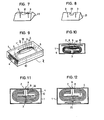
- Figures 7 and 8 are perspective views showing other forms of the container according to the present invention, being different from each other;
- Figure 9 is a perspective view, partially cut away, showing the general arrangement of a second embodiment of the construction for containing the plastics film according to the present invention;
- Figure 10 is a sectional view in the direction indicated by the arrows from line X-X in Fig. 9;
- Figures 11 and 12 are sectional views showing the states of containing the plate member and the film according to the present invention, being different from each other;
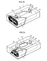
- Figures 13 and 14 are perspective views, partially cut away, showing the general arrangements of other embodiments of the insert member according to the present invention, being different from each other;
- Figures 15 through 17 are perspective views showing the appearances of other embodiments of the plate member according to the present invention, being different from one another;
- Figures 18 through 20 are perspective views showing other embodiments of the take-out opening provided on the plate member according to the present invention, being different from one another.
- Detailed description will hereunder be given of the embodiments of the present invention with reference to the drawings, in which same reference numerals are used to designate same or similar parts, so that the detailed description thereof need not be repeated.
- Figures 1 and 2 show the first embodiment of the construction for containing the plastics film according to the present invention, in which a
container 1 is made of paper board and formed into a hollow rectangular parallelepiped, and a rectangular take-outopening 2 is formed in the center of the upper surface of thiscontainer 1. Projectingly provided at the inner surface of thecontainer 1 and at opposite sides in a longitudinal direction of the take-outopening 2, i.e. in a lateral direction in Fig. 1, are insertmembers 3 directed inwardly (downwardly) of thecontainer 1. Eachinsert member 3 is formed of a soft-iron plate, in which an insert portion is formed of two layers capable of being bifurcated, and arranged in a T-shape in the initial state, not shown. Additionally, thisinsert member 3 is secured to thecontainer 1 such that the former is bonded to the latter, or the former is formed with a bendable tongue or tongues, which are extended through the latter to the outside, where the tongue or tongues are bent to be fixed thereat. - Contained in the
container 1 is aplastics film 4 in a folded state. Thisplastics film 4, as shown in Figure 3 for example, is of such an arrangement that a continuous tubular film formed by the inflation method or the like is folded along lines perpendicular to the longitudinal direction of the plastics film to be formed into double wall portions. Linear cuts 5 - penetrating through the double wall portion of thefilm 4 are formed in two lines at regular intervals in a cross-wise direction at the intermediate portion of the folded portion of the continuous plastics film in the longitudinal direction of the film.Perforated lines 6 are formed along the lines of linear cuts over the entire length in the crosswise direction except at the linear cuts. Thefilm 4 is connected in the longitudinal direction thereof at three portions in the cross-wise direction including at the central portion, by these portions ofperforated lines 6. Furthermore, aheat seal portion 7 is formed by fusion bonding between the double walls adjacent and along the respectivelinear cuts 5 andperforated lines 6, and thisheat seal portion 7 is formed over the entire length of the crosswise direction of thefilm 4 in parallel with theperforated lines 6, i.e., in a direction perpendicular to the longitudinal direction of thefilm 4. - The
abovedescribed film 4, as shown in Fig. 4, is staggeredly folded (folded in a Z-shaped manner) such that the respectivelinear cuts 5 are superposed on one another at the center. The thus folded, predetermined length sections of thefilm 4 are as shown in Figs. 1 and 2, contained in thecontainer 1 in the state of being bent into C-shapes downwardly open as viewed in looking toward the longitudinal side edges of thefilm 4. In this case, the aforesaid twoinsert members 3 are inserted through thelinear cuts 5 thus superposed, and ends of theinsert members 3, which have penetrated through all of the folded layers of thefilm 4, are bent towards opposite sides as shown in Fig. 2, so as to hold thefilm 4. - With the arrangement as described above, to take-out a predetermined length of the
film 4, i.e. a section of thefilm 4 to form a bag, a forward end of thefilm 4, which has previously partially projected from the take-outopening 2, is drawn out. In this case, when thefilm 4 folded and contained in thecontainer 1 is drawn out by a length of bag, an end of thefilm 4, constituting a second bag subsequent to the first one, engages theinsert members 3 because theinsert members 3 are inserted through thelinear cuts 5, with the result that the opposite end portions and the central portions of thefilm 4, where theperforated lines 6 are formed, are torn off by a resisting force due to the abovedescribed engagement. When torn off, thefilm 4 is drawn out of the take-outopening 2 formed in the center of thecontainer 1. Hence, when thefilm 4 is drawn out by a length of bag, part of the central portion of the succeeding portion of thefilm 4, connected to the first portion through theperforated lines 6, is drawn out of the take-outopening 2 because thelinear cuts 5 of thefilm 4 have widths to some extent and no resisting force is generated until theinsert members 3 inserted through thelinear cuts 5 reach the opposite end portions of thefilm 4 where connections are effected through theperforated lines 6. If the draw-out operation is continued in this condition, the opposite end portions of thefilm 4 connected to the succeeding section of thefilm 4 through theperforated lines 6 engage theinsert members 3 as if the former are wound around the latter. At this time, tensile forces act on the opposite end portions of thefilm 4, whereby, firstly, theperforated lines 6 at the opposite end portions begin to be cut. Thereafter, if the draw-out operation is further continued, a tensile force acts on the central portion of thefilm 4 due to a resisting force resulting from the engagement of the opposite end portions of thefilm 4 with theinsert members 3, whereby theperforated line 6 at the central portion is cut. In consequence, part of the succeeding section of thefilm 4 should project out of the take-out opening 2 without fail. - With this embodiment as described above, the
plastics film 4 can be reliably taken out in the same manner as in the pop-up take-out method of tissue paper, one section after another. Furthermore, the simplified construction thereof makes it possible to provide the containing construction at reduced cost. - Furthermore, in working the present invention, in place of the
plastics film 4, aplastics film 14 whose one longitudinal side edge is open, may be used as shown in Figure 5, or aplastics film 24 formed of a sheet may be used as shown in Figure 6. Theplastics film 14 shown in Figure 5 is provided with twolinear cuts 15 disposed at regular intervals in the longitudinal direction thereof,perforated lines 16 are provided at a position incorporating thelinear cuts 15, andheat seal portions 17 are provided at both sides of theperforated lines 16. Further, theplastics film 24 shown in Figure 6 is provided with twolinear cuts 25 disposed at regular intervals in the longitudinal direction thereof, andperforated lines 26 are provided at a position incorporating thelinear cuts 25. The same operations as those described above can be performed by use of thesefilms perforated lines linear cuts linear cuts film film linear cuts film insert members 3 are inserted at opposite sides of the take-out opening, then there are presented such advantages such that a resisting force present when thefilm film plastics film container 1 need not be limited to a C-shape, but, may be of any other shape. - Further, the
container 1 may be replaced by acontainer 11 having trapezoidal side surfaces as shown in Figure 7, acontainer 21 having triangular side surfaces as shown in Figure 8, or other containers having round side surfaces or elliptical side surfaces. Furthermore, the take-outopening 2 may be replaced by a take-out opening 12 of a circularly arcuate shape as viewed from the front as shown in Figure 7, a take-out opening 22 of a U-shape as viewed from the front as shown in Figure 8, or other take-out openings of a round or elliptical shape in plan view. - In the first embodiment described above, the
insert members 3 are directly provided on thecontainer 1. However, the insert members may be provided on aplate member 10 provided separately of thecontainer 1 as in the second embodiment shown in Figs. 9 and 10. More. specifically, in Figs. 9 and 10, a take-outopening 2 of an elliptical shape with opposite ends thereof cut away is formed in the center of the upper surface of thecontainer 1, this take-outopening 2 is covered with acover film 8 made of polyolefin, and thecover film 8 is provided at the central portion thereof with alinear cut 9 in the longitudinal direction of the take-outopening 2. - A
plate member 10 slightly smaller than the inside dimensions of thecontainer 1 and capable of being readily put into and taken out of thecontainer 1 is disposed inside a surface of thecontainer 1 where the take-out opening is formed. Thisplate member 10 is made of a material such as paper or plastics, but is not restricted in material quality in particular. - Formed at the central portion of the above- mentioned
plate member 10 is a take-outopening 32 of an elliptical shape with opposite ends thereof cut away, corresponding to the take-outopening 2 of thecontainer 1. Theinsert members 3 downwardly project at longitudinally opposite ends of this take-outopening 32 as seen in Figure 9, and engage a surface of theplate member 10 opposite the surface thereof contacting an inner surface of thecontainer 1, i.e., engage the undersurface of the plate member in Figure 9. Thisinsert member 3, in the same manner as in the abovedescribed first embodiment, is formed of a soft-iron plate, in which an insert portion is formed of two layers capable of being bifurcated, and arranged in a T-shape in the initial state, not shown. Additionally, theseinsert members 3 are secured to theplate member 10 by bonding or penetrating theplate member 10 with theinsert members 3. - The
insert members 3 on theplate member 10 are inserted through theplastics film 4 in the folded state in the same manner as in the aforesaid first embodiment, in which theinsert members 3 are directly provided on thecontainer 1. Thefilm 4 of the predetermined length in this state is contained in thecontainer 1 in a condition, where the film is folded substantially in a C-shape downwardly open as viewed in looking toward the longitudinal side edge of thefilm 4 shown in Figures 9 and 10. In this case, the aforesaid twoinsert members 3 are inserted through the superposedlinear cuts 5, and the end portions of theinsert members 3, which have penetrated through thefilm 4 as a whole, are bent to the opposite sides as shown in Fig. 10, so that thefilm 4 can be held. Thefilm 4, thus engaged with theinsert members 3 of theplate members 10 as described above, is contained together with theplate member 10 in theaforesaid container 1. - The process of manufacture of this second embodiment is such that, firstly, the
insert members 3 are secured to theplate member 10 by the aforesaid manner, theinsert members 3 are inserted through thelinear cuts 5 of the foldedfilm 5 to engage thefilm 4 with the insert members, and then thefilm 4 and theplate member 10 are integrally received in thecontainer 1. - In this embodiment as described above, such a construction is adopted that the
insert members 3 engaging thefilm 4 are provided on theplate member 10 formed separately of thecontainer 1, so that the work of mounting theinsert members 3 can be simplified and the work of engaging thefilm 4 with theinsert members 3 can be performed outside thecontainer 1, to thereby improve the serviceability and facilitate the automation of the manufacturing process. - Since the outside dimensions of the
plate member 10 are slightly smaller than the inside dimensions of thecontainer 1, the serviceability is improved when theinter-engaged plate member 10 andplastics film 4 are inserted into thecontainer 1. Further, since thecontainer 1 and theplate member 10 are only slightly different in dimensions, the possibility is eliminated that the movement of theplate member 10 after being placed in thecontainer 1 could cause the take-outopening 2 of thecontainer 1 and the take-outopening 32 of theplate member 10 to be offset from each other. - The
polyolefin cover film 8 provided at the take-outopening 2 of thecontainer 1 in this embodiment is intended mainly for improving the appearance of thecontainer 1 and for excluding dust from the containedplastics film 4, and hence is not essential from the viewpoint of taking thefilm 4 out one piece after another. - The orientation of the
plastics film 4 in thecontainer 1 need not be limited to the C-shape downwardly opening, but may be inverted, with the C-shape upwardly opening towards the take-outopening 2 as shown in Figures 11 and 12. In this case, theplate member 10 may face toward the take-outopening 2 as shown in Figure 11, or theinsert members 3 may face toward the take-outopening 2 as shown in Figure 12. When theinsert members 3 face toward the take-outopening 2 as shown in Figure 12, theplate member 20 is not required to have the take-out opening and only functions as a member for holding theinsert members 3. - The
insert members 3 need not be limited to ones formed of soft-iron plates as in the first and second embodiments, but may beinsert members 33 formed of wire-reinforced plastics tapes as shown in the third and the fourth embodiments in Figures 13 and 14. More specifically, referring to Figs. 13 and 14, theinsert member 33 formed of the wire-reinforced tape may be of such an arrangement that theinsert member 33 is once bent into substantially a U-shape, then opposite end portions thereof are inserted through a pair of mountingholes 40 penetratingly provided in thecontainer 1 or theplate member 10, respectively, once twisted together, and thereafter extended to opposite sides, as to engage the plastics film. Further, theinsert member 33 may be formed of wires coated with a synthetic resin material or a rubbery material, or formed of wires only in place of the wire-reinforced plastics tape. Still further, theinsert member 33 may be of a single bar shape, a plate shape, a cord shape, a thread shape or the like. In this case, the material of theinsert member 3 should not necessarily be limited to the aforesaid soft-iron plate, wires or the like, but may be of other types of metal, wood, paper, plastics, fibers or other materials. When theinsert member 3 is formed of a cord or a thread, the outer end portion of theinsert member 3 is fixed to somewhere in thecontainer 1 or the opposinginsert members 3 are connected to each other, for rigidity sufficient for tearing thefilm 4 off by means of theinsert members 3. - Furthermore, in the aforesaid second embodiment, the form of the
plate member 10 need not necessarily be of a flat board, but may be of a three dimensional form, for example semicircular, triangular, trapezoidal or the like in cross section as shown in Figures 15 through 17. In this case of adopting one of the forms as described above, even if the remaining quantity of thefilm 4 becomes small, theplate member 10 will not sink to the bottom of thecontainer 1, thereby offering the advantage that the take-out of thefilm 4 is facilitated. The shape of the take-outopening 32 formed at the center of theplate 10 may be a circular or elliptical one. Further, such shape may be a rectangular one or a slit-shaped one or a slit-shaped one with the both side edges thereof turned back or the like as shown in Figures 18 through 20, in addition to the elliptical one with the opposite end portions thereof being cut away as shown in the abovedescribed embodiment. Furthermore, the shape of the take-outopening 2 of thecontainer 1 need not necessarily be limited to the elliptical one with the opposite end portions thereof cut away, but such shape may be circular, elliptical, rectangular, slit-shaped or slit-shaped with the both side edges thereof turned back or the like. - If the
container 1 is fixed to a wall or the like by means of a bonding agent or a metal fixture, then it becomes possible to take out the plastic film by use of one hand only. In this case, if the abovedescribed embodiment using theplate member 10 is fixed to a wall or the like with the take-outopening 2 thereof facing straight downwardly, then, as theplastics film 4 is drawn out and reduced in quantity, theplate member 10 also descends straight downwardly, and hence the advantage results that even if the remaining portion of theplastics film 4 becomes small in quantity, thefilm 4 still can be easily taken out through the take-outopening 2.
Detailed description of the preferred embodiments
Claims (8)
Priority Applications (1)
| Application Number | Priority Date | Filing Date | Title |
|---|---|---|---|
| AT81109030T ATE11516T1 (en) | 1980-11-28 | 1981-10-27 | CONTAINER FOR A PLASTIC FILM. |
Applications Claiming Priority (4)
| Application Number | Priority Date | Filing Date | Title |
|---|---|---|---|
| JP55168412A JPS5940702B2 (en) | 1980-11-28 | 1980-11-28 | plastic film packaging |
| JP168412/80 | 1980-11-28 | ||
| JP28093/81 | 1981-02-27 | ||
| JP2809381A JPS5940703B2 (en) | 1981-02-27 | 1981-02-27 | plastic film packaging |
Publications (2)
| Publication Number | Publication Date |
|---|---|
| EP0053282A1 EP0053282A1 (en) | 1982-06-09 |
| EP0053282B1 true EP0053282B1 (en) | 1985-01-30 |
Family
ID=26366131
Family Applications (1)
| Application Number | Title | Priority Date | Filing Date |
|---|---|---|---|
| EP81109030A Expired EP0053282B1 (en) | 1980-11-28 | 1981-10-27 | Construction for containing plastics film |
Country Status (5)
| Country | Link |
|---|---|
| US (1) | US4453649A (en) |
| EP (1) | EP0053282B1 (en) |
| CA (1) | CA1156618A (en) |
| DE (1) | DE3168678D1 (en) |
| GB (1) | GB2088329B (en) |
Families Citing this family (41)
| Publication number | Priority date | Publication date | Assignee | Title |
|---|---|---|---|---|
| JPS5899372A (en) * | 1981-12-01 | 1983-06-13 | 出光興産株式会社 | Encasing structure of plastic film |
| US4813593A (en) * | 1983-06-22 | 1989-03-21 | Moore Business Forms, Inc. | Continuous business form assembly of mailer units including detachment slits |
| US4562938A (en) * | 1984-04-02 | 1986-01-07 | Minnesota Mining And Manufacturing Company | Sheet dispenser |
| US4586630A (en) * | 1984-04-02 | 1986-05-06 | Minnesota Mining And Manufacturing Company | Dispensing package for sheets |
| JPS6122779U (en) * | 1984-07-14 | 1986-02-10 | 利宗 増井 | tissue paper storage box |
| US4567984A (en) * | 1984-08-17 | 1986-02-04 | Custom Machinery Design, Inc. | Plastic bag package |
| US4597494A (en) * | 1984-12-31 | 1986-07-01 | Mobil Oil Corporation | Horseshoe folded and center unwound plastic bags |
| DE8500687U1 (en) * | 1985-01-14 | 1986-05-15 | Henkel KGaA, 4000 Düsseldorf | Drug cloth |
| US4674634A (en) * | 1985-06-21 | 1987-06-23 | Minnesota Mining And Manufacturing Company | Package of reclosable plastic bags |
| US4696744A (en) * | 1986-01-27 | 1987-09-29 | Raymond Sedlacek | Coffee filters and dispenser container therefor |
| US4805800A (en) * | 1986-09-04 | 1989-02-21 | Minigrip, Inc. | Dispenser for plastic bags |
| US4805969A (en) * | 1987-06-04 | 1989-02-21 | Stephanie Heacock | Bag holder |
| US4849090A (en) * | 1988-05-11 | 1989-07-18 | Sonoco Products Company | Bag roll |
| US5046619A (en) * | 1990-04-05 | 1991-09-10 | Hwang Feng Lin | Mini-package structure of rubbish bags |
| US5269423A (en) * | 1992-03-16 | 1993-12-14 | Advance Polybag, Inc. | Bag dispenser system |
| US5348399A (en) * | 1992-12-23 | 1994-09-20 | Dematteis Robert B | Plastic bags with waveform edge configurations |
| GB9504613D0 (en) * | 1995-03-08 | 1995-04-26 | Welton Packaging Limited | Bag dispensing arrangements |
| USD398841S (en) | 1996-04-02 | 1998-09-29 | Tim Sargent | Trash bag receptacle |
| US6378726B1 (en) | 1996-11-22 | 2002-04-30 | Kimberly Clark Worldwide, Inc. | Interfolded napkin dispensing system |
| US6286713B1 (en) | 1997-03-13 | 2001-09-11 | Kimberly-Clark Worldwide, Inc. | Dispensing system for individual folded webs |
| GB9705549D0 (en) * | 1997-03-18 | 1997-05-07 | Edmonstone Lady | Improvements relating to bin liners |
| US5890351A (en) * | 1997-09-22 | 1999-04-06 | Y. S. Kim | Disposable bag maker |
| GB9822943D0 (en) | 1998-10-20 | 1998-12-16 | Cascade Dispensers Ltd | Dispensers for bags |
| US6508381B1 (en) | 2000-11-28 | 2003-01-21 | Ahmed Sadi | Bag dispensing assembly |
| US6439386B1 (en) * | 2000-11-30 | 2002-08-27 | Kimberly-Clark Worldwide, Inc. | Packaged absorbent paper product, container, and dispensing method |
| US6588626B2 (en) | 2000-11-30 | 2003-07-08 | Kimberly-Clark Worldwide, Inc. | Optionally hangable container and dispensing method |
| US6575301B2 (en) * | 2001-07-16 | 2003-06-10 | Ebrahim Simhaee | Plastic bag package |
| CA2359265A1 (en) * | 2001-08-10 | 2003-02-10 | Robert V. Dailey, Iii | Cloth dispenser system |
| US20030136793A1 (en) * | 2002-01-22 | 2003-07-24 | Chih-Shen Chen | Plastic bag dispenser and manufacturing method thereof |
| US7624881B2 (en) * | 2004-01-20 | 2009-12-01 | Hilex Poly Co., Llc | Dispensing apparatus for plastic bags |
| US20060261079A1 (en) * | 2005-05-19 | 2006-11-23 | Ahmed Sadi | Bag dispensing assembly |
| US20070235467A1 (en) * | 2006-04-10 | 2007-10-11 | Potlatch Forest Products Corporation | Paper tissue dispenser |
| WO2009043072A1 (en) * | 2007-10-01 | 2009-04-09 | Ciggybag Gmbh | Arrangement for disposing of cigarette and cigarillo butts |
| US20090288908A1 (en) * | 2007-11-30 | 2009-11-26 | Giroux Jennifer S | Protective-sleeve cartridge and stethoscope incorporating same |
| CA2680970A1 (en) | 2009-09-28 | 2011-03-28 | Labplas Inc. | Biodegradable sterile sampling bag |
| US9572462B2 (en) * | 2012-02-23 | 2017-02-21 | Georgia-Pacific Consumer Products Lp | Napkin dispenser |
| US9266663B1 (en) * | 2013-02-07 | 2016-02-23 | Ronald T. Lee | Coffee filter roll, coffee filter dispensing system, and a method of dispensing rolled coffee filters |
| US9926158B2 (en) * | 2014-03-31 | 2018-03-27 | Labplas Inc. | Sterile sampling bag, roll of bags, and bag dispenser |
| US20170305606A1 (en) * | 2016-04-25 | 2017-10-26 | Better Bags, Inc. | Packs of Plastic Bags and Racks for Suspending The Packs of Plastic Bags |
| USD815853S1 (en) | 2016-07-25 | 2018-04-24 | Labplas Inc. | Dispenser for roll of bags |
| US12552597B2 (en) * | 2024-05-01 | 2026-02-17 | 2574718 Alberta LTD. | Packaged grain/silage bag |
Family Cites Families (15)
| Publication number | Priority date | Publication date | Assignee | Title |
|---|---|---|---|---|
| US425033A (en) * | 1890-04-08 | Bundle of toilet or wrapping paper | ||
| DE71705C (en) * | E. N. CUMMINGS, Nr. 2 Rogers Avenue, Lynn, County of Essex, Massachusetts, V. St. A.; VerKlasse : treter: A. MÜHLE und W. ZlOLECKI in Berlin W., Friedrichstr. 78 | Abortion or wrapping paper pad | ||
| US733283A (en) * | 1902-11-21 | 1903-07-07 | Arthur Hoyt Scott | Toilet-paper. |
| US1170590A (en) * | 1915-01-14 | 1916-02-08 | Seth Wheeler | Paper-roll. |
| US3186542A (en) * | 1962-01-30 | 1965-06-01 | Parachem Corp | Slide pack sheet dispenser |
| US3266666A (en) * | 1965-01-12 | 1966-08-16 | Kimberly Clark Co | Tissue dispensing carton having a detachable control panel as an integral part of the top wall |
| US3338398A (en) * | 1966-07-29 | 1967-08-29 | Eagle Picher Co | Flexible plastic bag package |
| US3369699A (en) * | 1966-08-18 | 1968-02-20 | Kimberly Clark Co | Sheet dispensing device |
| US3473694A (en) * | 1967-08-25 | 1969-10-21 | Int Paper Canada | Carton |
| DE2134315A1 (en) * | 1971-03-04 | 1972-09-21 | Bio-Medical Sciences Inc., Fairfield, N.J.(V.St.A.) | Thermometer as well as dispenser for the same |
| JPS52431A (en) * | 1975-06-23 | 1977-01-05 | Fujikura Ltd | Process for producing optical fiber |
| US3979019A (en) * | 1975-08-07 | 1976-09-07 | Hoerner Waldorf Corporation | Dispensing closure for tissue carton |
| FR2387182A1 (en) * | 1977-04-14 | 1978-11-10 | Vila Omella Ramon | Combined packaging and dispenser for plastics bags - has corner suspension hole each side of central perforation forming mouth of bag by tearing whilst removing |
| JPS5452431U (en) * | 1977-09-17 | 1979-04-11 | ||
| US4305503A (en) * | 1980-04-24 | 1981-12-15 | Hercules Membrino | Package of plastic bags |
-
1981
- 1981-10-27 EP EP81109030A patent/EP0053282B1/en not_active Expired
- 1981-10-27 DE DE8181109030T patent/DE3168678D1/en not_active Expired
- 1981-10-28 US US06/315,815 patent/US4453649A/en not_active Expired - Fee Related
- 1981-10-30 GB GB8132805A patent/GB2088329B/en not_active Expired
- 1981-11-16 CA CA000390184A patent/CA1156618A/en not_active Expired
Also Published As
| Publication number | Publication date |
|---|---|
| GB2088329B (en) | 1984-05-10 |
| CA1156618A (en) | 1983-11-08 |
| DE3168678D1 (en) | 1985-03-14 |
| EP0053282A1 (en) | 1982-06-09 |
| US4453649A (en) | 1984-06-12 |
| GB2088329A (en) | 1982-06-09 |
Similar Documents
| Publication | Publication Date | Title |
|---|---|---|
| EP0053282A1 (en) | Construction for containing plastics film | |
| US4506801A (en) | Construction for holding plastic film | |
| US4738546A (en) | Package bag and method of manufacturing the same | |
| EP0051914B1 (en) | Self-locking ribbon assemblies | |
| KR970010109A (en) | Zippered film and bag | |
| JPH08712U (en) | Clamp | |
| US6296389B1 (en) | Easy-to-open packing bag | |
| US3085738A (en) | Flat bag with an adhesive seal | |
| US5265962A (en) | Packing bag having drawstrings | |
| CA2159926C (en) | Resealable pack | |
| US4700883A (en) | Tubular package and end cap forming component of same | |
| US5676299A (en) | Staple refill cartridge for electric stapler | |
| JPH09207948A (en) | Packaging bag | |
| US4688673A (en) | Foldup paper container | |
| US5180229A (en) | Sampling bag with enclosed wire ends | |
| JP4028068B2 (en) | Carton for wrap film | |
| JPS5940703B2 (en) | plastic film packaging | |
| JPS6383186A (en) | Adhesive tape | |
| JPS6042103B2 (en) | Synthetic resin bag | |
| JPH08230943A (en) | Auxiliary tape for unsealing bag, and package bag | |
| JPH0872864A (en) | Rain gutter packaging structure | |
| JP2540409Y2 (en) | Seat storage container | |
| JP3014632U (en) | Thin wall container made of sheet material | |
| JPH0330258Y2 (en) | ||
| JPH027817Y2 (en) |
Legal Events
| Date | Code | Title | Description |
|---|---|---|---|
| PUAI | Public reference made under article 153(3) epc to a published international application that has entered the european phase |
Free format text: ORIGINAL CODE: 0009012 |
|
| 17P | Request for examination filed |
Effective date: 19811027 |
|
| AK | Designated contracting states |
Designated state(s): AT BE CH DE FR IT LU NL SE |
|
| ITCL | It: translation for ep claims filed |
Representative=s name: ING. FRANCO PATRITO |
|
| TCAT | At: translation of patent claims filed | ||
| DET | De: translation of patent claims | ||
| ITF | It: translation for a ep patent filed | ||
| GRAA | (expected) grant |
Free format text: ORIGINAL CODE: 0009210 |
|
| AK | Designated contracting states |
Designated state(s): AT BE CH DE FR IT LI LU NL SE |
|
| REF | Corresponds to: |
Ref document number: 11516 Country of ref document: AT Date of ref document: 19850215 Kind code of ref document: T |
|
| REF | Corresponds to: |
Ref document number: 3168678 Country of ref document: DE Date of ref document: 19850314 |
|
| ET | Fr: translation filed | ||
| PG25 | Lapsed in a contracting state [announced via postgrant information from national office to epo] |
Ref country code: LU Free format text: LAPSE BECAUSE OF NON-PAYMENT OF DUE FEES Effective date: 19851031 |
|
| PLBE | No opposition filed within time limit |
Free format text: ORIGINAL CODE: 0009261 |
|
| STAA | Information on the status of an ep patent application or granted ep patent |
Free format text: STATUS: NO OPPOSITION FILED WITHIN TIME LIMIT |
|
| 26N | No opposition filed | ||
| PGFP | Annual fee paid to national office [announced via postgrant information from national office to epo] |
Ref country code: LU Payment date: 19890913 Year of fee payment: 9 |
|
| PGFP | Annual fee paid to national office [announced via postgrant information from national office to epo] |
Ref country code: BE Payment date: 19890929 Year of fee payment: 9 |
|
| PGFP | Annual fee paid to national office [announced via postgrant information from national office to epo] |
Ref country code: AT Payment date: 19891013 Year of fee payment: 9 |
|
| PGFP | Annual fee paid to national office [announced via postgrant information from national office to epo] |
Ref country code: FR Payment date: 19891018 Year of fee payment: 9 |
|
| PGFP | Annual fee paid to national office [announced via postgrant information from national office to epo] |
Ref country code: SE Payment date: 19891019 Year of fee payment: 9 |
|
| PGFP | Annual fee paid to national office [announced via postgrant information from national office to epo] |
Ref country code: CH Payment date: 19891026 Year of fee payment: 9 |
|
| ITTA | It: last paid annual fee | ||
| PGFP | Annual fee paid to national office [announced via postgrant information from national office to epo] |
Ref country code: NL Payment date: 19891031 Year of fee payment: 9 |
|
| PGFP | Annual fee paid to national office [announced via postgrant information from national office to epo] |
Ref country code: DE Payment date: 19891130 Year of fee payment: 9 |
|
| PG25 | Lapsed in a contracting state [announced via postgrant information from national office to epo] |
Ref country code: AT Effective date: 19901027 |
|
| PG25 | Lapsed in a contracting state [announced via postgrant information from national office to epo] |
Ref country code: SE Effective date: 19901028 |
|
| PG25 | Lapsed in a contracting state [announced via postgrant information from national office to epo] |
Ref country code: LI Effective date: 19901031 Ref country code: CH Effective date: 19901031 Ref country code: BE Effective date: 19901031 |
|
| BERE | Be: lapsed |
Owner name: IDEMITSU KOSAN CY LTD Effective date: 19901031 |
|
| PG25 | Lapsed in a contracting state [announced via postgrant information from national office to epo] |
Ref country code: NL Effective date: 19910501 |
|
| NLV4 | Nl: lapsed or anulled due to non-payment of the annual fee | ||
| PG25 | Lapsed in a contracting state [announced via postgrant information from national office to epo] |
Ref country code: FR Effective date: 19910628 |
|
| REG | Reference to a national code |
Ref country code: CH Ref legal event code: PL |
|
| PG25 | Lapsed in a contracting state [announced via postgrant information from national office to epo] |
Ref country code: DE Effective date: 19910702 |
|
| REG | Reference to a national code |
Ref country code: FR Ref legal event code: ST |
|
| EUG | Se: european patent has lapsed |
Ref document number: 81109030.7 Effective date: 19910603 |