EP0052902A1 - Method and device for character segmentation - Google Patents
Method and device for character segmentation Download PDFInfo
- Publication number
- EP0052902A1 EP0052902A1 EP81201232A EP81201232A EP0052902A1 EP 0052902 A1 EP0052902 A1 EP 0052902A1 EP 81201232 A EP81201232 A EP 81201232A EP 81201232 A EP81201232 A EP 81201232A EP 0052902 A1 EP0052902 A1 EP 0052902A1
- Authority
- EP
- European Patent Office
- Prior art keywords
- character
- grey
- segment
- value
- values
- Prior art date
- Legal status (The legal status is an assumption and is not a legal conclusion. Google has not performed a legal analysis and makes no representation as to the accuracy of the status listed.)
- Ceased
Links
Images


Classifications
-
- G—PHYSICS
- G06—COMPUTING OR CALCULATING; COUNTING
- G06V—IMAGE OR VIDEO RECOGNITION OR UNDERSTANDING
- G06V30/00—Character recognition; Recognising digital ink; Document-oriented image-based pattern recognition
- G06V30/10—Character recognition
- G06V30/14—Image acquisition
- G06V30/148—Segmentation of character regions
- G06V30/158—Segmentation of character regions using character size, text spacings or pitch estimation
-
- G—PHYSICS
- G06—COMPUTING OR CALCULATING; COUNTING
- G06V—IMAGE OR VIDEO RECOGNITION OR UNDERSTANDING
- G06V30/00—Character recognition; Recognising digital ink; Document-oriented image-based pattern recognition
- G06V30/10—Character recognition
Definitions
- the invention relates to a method and a device for segmenting substantially fixed-pitch aligned characters, in which each character is converted into an image-element pattern.
- addresses on postal articles consist of substantially fixed-pitch type-writer or line-printer characters. Nevertheless, owing to machine defects, these characters may exhibit such pitch deviations as to become hardly segmentable.
- Recognizing a fundamental frequency in a signal is known per se from speech recognition technique, which, however, does not present the problem of spaces as in lines of characters.
- the very presence of these spaces in a character line can influence the fundamental frequency of the signal derived from the character line considerably.
- This procedure has the disadvantage that overlapping characters, or underlining of the character line, may disturb the functioning. Besides, it may be important, e.g. when recognizing characters on postal articles, to be able to recognize a specified group of characters.
- the method and the device according to the invention are based upon the insight that the character pitch can be determined in a simple manner for an entire character line by applying, one by one, several combs having different tooth pitches to the character line and seeing, for each comb, how many characters and spaces are recognized by reading between the teeth.
- the outermost character position is determined by attributing a grey-value to each of the elements making up the character image;by summing the grey-values of the image elements per column; by determining, in a constant proportion, a maximum, a minimum and a threshold of summed grey-values for the entire character line to be segmented and by selecting as outermost character position the set of grey-values summed per column, of which, seen from the end of the character line, the first column grey-value exceeds the threshold grey-value.
- each of the segments is examined at a fixed number of points, of which, in the case the centre-line of a segment of a suitable width coincides with the centre-line of a character, at least one falls at one side and at least one falls at the other side of the character, at least one of the remaining points coinciding with a grey-value column of the character.
- the invention provides a device for carrying out said method(s), comprising means for synchronizing the first segment with the first character on the character line, means for dividing the character line into segments, means for classifying the information found in each of the segments as a character, as a space or as a. non-space and means for comparing the classification results obtained with the segment widths examined.
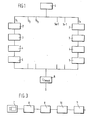
- Fig. 1 in the shape of a functional block diagram, gives an impression of the method according to the invention.
- the character line is digitized in a manner known per se.
- step 2 a start position is found for a first pitch S.
- step 3 the content is determined for every segment of the pitch chosen..
- step 4 it is determined which segments contain characters, which contain spaces and which contain non-spaces.
- step 5 a correlation factor is fixed for the results obtained by step 4 for the pitch chosen.
- the digitizing process comprising the conversion of a character line image into an image element pattern and the vertical projection thereof.
- Fig. 2a represents a character line at random. This character line is converted first into an image element pattern (Fig. 2b). Now a value is attributed to each of the image elements, which is a measure for the grey-value of that image element. Then these grey-values of image elements are summed per column.
- Fig. 2c is a diagram of the grey-values thus added. For simplicity's sake, one and the same grey-value has been attributed to each of the image elements and the number of elements per character has greatly been reduced. In practice, the height of a character corresponds to approximately 32 image elements, the width of a character line to 256 image elements and the shade of grey of each character element can be expressed in 256 values.
- a segment width S is chosen. In practice, it proves sufficient when the smallest segment width chosen corresponds to 9 image elements and the largest corresponds to 30 image elements. In order to avoid that a large and varying number of column values has to be examined for each segment, a segment will be considered described by a small and fixed number of columns. In the embodiment described there are five columns.
- left-hand valley LV
- RV right-hand valley
- LP left-hand peak
- MP middle peak
- RP right-hand peak
- the maximum value MAX and the minimum value MIN of all the grey-value columns (Fig. 2c) of the entire line are determined.
- MIN need not necessarily be zero; if the character line to be segmented is underlined, MIN will give the grey-value of the underlining.
- SPF segment-positioning factor
- the grey-value column in which this level occurs first is designated by k 0 .
- the SPF is determined for every grey-value column for which
- the grey-value column in which SPF is a maximum is called k and is considered start position for the line. Now the grey-value column k 1 is deemed to coincide with the left-hand valley LV of the first segment w 1 .
- the combined steps described, provided for synchronizing the first segment with the first character, are referred to as synchronization.
- the SPF for the area between k 1 and k 1 + S is determined first.
- the values for k and SPF are recorded in one store.
- the starting-line for the next segment is determined by k 1 + S.
- the SPF is determined of each of the segments beginning at k 2 - 1, k 2 and k 2 + 1, respectively.
- the k-value with which the largest SPF is found is regarded as the correct one and serves as starting-point for determining k3. If, however, no grey-values exceeding the value THRES are found over a width S, the segment is assumed to contain a space and the next k is determined by k w + S. In.this manner a starting value k is determined for each segment w, as well as a value for SPF and the values LV, LP, MP, RP and RV.
- an average value LAV and a standard deviation SD are determined for all the values of LV and RV.
- the average value LAV represents the background noise, which can also result from the above-mentioned underlining of the character line. So in the case of a correct segmentation, the background noise L 0 can be defined as
- each grey-value column is normalized between L 0 and L 0 + Q (formula 6).
- the values thus normalized for LV, LP, MP, RP and RV are designated by LV', LP',MP', RP' and RV', respectively.
- the total value -TSC for a line divided into segments is determined by summing the values of all the segments.
- the correlation factor referred to hereinabove is determined by the value TSC, the number of segments U in which a character is found, the number of segments V in which a space is found, the standard deviation SD and the value Q that has been found, in the following proportion:
- a process as has been described in the above paragraphs 2 to 5 is carried out on each of the segment widths deemed possible.
- a correlation factor C F can be determined for each of these pitches. It is clear that the pitch giving the highest correlation factor C F is the most probable pitch.
- the method according to the invention thus provides a reliable segmentation of characters and spaces on a character line and has the particular advantage that, thanks to the designation of each segment, certain groups of spaces and characters can easily be recognized. Thus the place of a postcode can be detected in a simple manner.
- the device according to the invention consists substantially of the parts represented in Fig. 3. It comprises a reading unit 7, which converts the optical signal of the character lines to be segmented into an electric signal consisting of image elements. Such a unit may comprise a TV camera or a series of diodes and is otherwise generally known.
- a pre-processing unit 8 ensures the detecting and correcting of crooked character lines or characters that are not printed straight.
- the width of a character line comprises 256 image elements, so that the total information digitized by the pre-processor 8 can be represented by 256 x 13 bits.
- the process by which this is done is generally known and will not be explained here, since it is no essential part of the present invention.
- a classifying unit 10 classifies the segments found according to their nature - character space or non-space - by the criteria elucidated hereinabove.
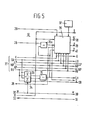
- Fig. 5 is a more detailed representation of the classifying unit.
- the classification data found are fed to a correlation circuit 11, which determines the maximum correlation factor.
- the electric analogue of the image elements projected, which is fed to the synchronizing and segmenting unit 9, is recorded in a 256 x 13 bit addressable store (RAM) 12 (Fig. 4).
- a comparator 13 determines the levels THRES and MAX, after which a comparator-counter 14 detects the first image-element column k 0 of which the value recorded in store 12 exceeds the THRES-level.
- a comparator-counter 15 compares the values stored in 12 over a number of steps between the limits k 0 ⁇ S V , for which the value indicated by store (ROM) 16 is used. In the first cycle the value stored in ROM 16, representing the examined segment width in image-elements, will remain unchanged. In practice a lowest value of 9 image elements for Sv proves to be amply sufficient.
- a generator 17 generates the values for column k at which the first character is assumed to be present and compares the value of k with that of a detector 18, which can determine the highest value of the co-ordinate in store 12 at which a possible character is still detected.
- a counter-store 19 determines the next value every time after a first value k has been found, as explained in the method description.
- a comparator 20 examines whether the area indicated by the k-generator 17 contains a sufficient number of values.
- a segment dividing circuit 21 determines, on the basis of the content of store 12, the segment width concerned and the k-values given by generator 17, the positions of five points P 02 P 1 , P 2 , P 3 and P 4 ; in practice, the following positions prove to result in a suitable distribution, with the relevant values of w and S V :
- a segment positioning circuit 22 derives the segment positioning factor from the values LV, LP, MP, RP and RV found at points P 0 to P 4 by formula (2) stated hereinabove.
- a comparator 23 holds the latest SPF-value and replaces it by a next, if this next value is larger.
- the values LV, LP, MP, RP and RV associated with the largest SPF-value are recorded every time in a store 24.
- the initial co-ordinate k and the co-ordinates of points P 0 to P 4 for which SPF is a maximum are recorded column by column in a tabular RAM 25 for every segment number w supplied by classification unit 10 via input 26.
- circuit 9 has output terminals 27, via which the values recorded in store 25 can be passed to the further circuit; output terminals 28, 29, 30 and 31, for outputting the maximum cumulative grey-value level, the content of store 12, the total number of segments W of the line and the number of image points per segment S, respectively, and an input terminal 32, for changing the address of store 16 in order to set a different value for the pitch S.
- the classification unit 10, represented in more detail in Fig. 5, comprises an adder 33, which adds up the values LV and RV from store 25, in order to determine the average value LAV of the grey-values in the left-hand and right-hand valley of each segment. Therefore adder 33 carries out the following operation:
- a circuit 34 calculates the standard deviation SD of the values LV and RV. As has been observed already, these two values are a measure for the correctness of the segment.width S chosen, since, with a correct .,segment width the standard deviation SD will be nearly equal to zero.
- a subtracter 35 determines the difference between the average value LAV and the standard deviation SD.
- a subtracter 35a subtracts the value found by 35 from the maximum grey-level MAX and the value Q thus found - see formula (6) - is fed to a decision circuit 36, which, on the basis of the values of the pitch S set, the number of segments W, the summed grey-values LV, LP, MP, RP and RV, the co-ordinates k and the values stored in register 12 (Fig.
- Correlation circuit 11 contains a threshold element 41 for normalizing each of the values LV, LP, MP, RP and RV with respect to the average grey-value L 0 and the value Q.
- a selector 43 passes, in the case of a space, the value "0" to its output, and if the relevant segment contains no space, it passes the value fixed by 42.
- An integrator 44 adds up the values fixed by circuit 42 for all segments, in order to find the TSC-value.
- Computing-circuit 45, computing-circuit 46 and computing-circuit 47 calculate the three factors for formula 11, after which multiplier 48 determines the value for C F .
- a difference circuit 49 compares the value of C F with preceding C F - values associated with other S-values and passes, via output 50, a signal back to input 32 -(Fig. 4), in order to set ROM 16 to the next value of S. Every time, a store 51 records the largest value found for C F , together with the associated segment width S. When a correlation factor C F has been determined for each of the S-values, the value of the segment width S for which the correlation factor C - is a maximum appears at output 52. It is self-evident that the device described above for carrying out the method(s) according to the invention is only one of a plurality of embodiments.
- the character and space patterns can be derived from the outputs 27 of store 25, so that the place of a specified character configuration, as a postcode, can be derived in a simple manner.
- the invention thus provides a device for carrying out the method described hereinabove, which, even with a poor quality of print, guarantees a good segmentation of the character line.
Landscapes
- Engineering & Computer Science (AREA)
- Computer Vision & Pattern Recognition (AREA)
- Physics & Mathematics (AREA)
- General Physics & Mathematics (AREA)
- Multimedia (AREA)
- Theoretical Computer Science (AREA)
- Character Input (AREA)
Abstract
Each character is converted into a pattern of image elements. The image elements form columns and rows. The grey-values of the image elements are summed per column and the summed column values are put in relation with a fixed number of columns per character (1). After the outermost character position on a line has been found (2), a first segmenting process is carried out on the basis of a first probable distance between characters (3). After the segmenting process has been carried out for several different character distances (S, - Sn), the correlation factor is determined (6), by means of which the segmentation, which precedes the character recognition, is carried out.
Description
- The invention relates to a method and a device for segmenting substantially fixed-pitch aligned characters, in which each character is converted into an image-element pattern.
- Methods and devices of this kind are common knowledge. A disadvantage of known devices is that they are less suited for segmenting characters of poor quality.
- In particular, addresses on postal articles consist of substantially fixed-pitch type-writer or line-printer characters. Nevertheless, owing to machine defects, these characters may exhibit such pitch deviations as to become hardly segmentable.
- Recognizing a fundamental frequency in a signal is known per se from speech recognition technique, which, however, does not present the problem of spaces as in lines of characters. The very presence of these spaces in a character line can influence the fundamental frequency of the signal derived from the character line considerably. To avoid this disadvantage, it has been proposed to isolate the characters and to pass them consecutively to a recognition device in order to be recognized.
- This procedure has the disadvantage that overlapping characters, or underlining of the character line, may disturb the functioning. Besides, it may be important, e.g. when recognizing characters on postal articles, to be able to recognize a specified group of characters.
- It is an object of the invention to provide a method and a device of the above-mentioned type which do not present said difficulties. The method and the device according to the invention are based upon the insight that the character pitch can be determined in a simple manner for an entire character line by applying, one by one, several combs having different tooth pitches to the character line and seeing, for each comb, how many characters and spaces are recognized by reading between the teeth.
- The method according to the invention to be described hereinafter employs an electrical analogue of this procedure. Therefore the method according to the invention is characterized by
- - determining an outermost character position on the character line to be segmented;
- - successively dividing the character line, with several different fixed pitches, into segments, starting from the outermost character position;
- - classifying each segment, with the aid of fixed criteria, according to its content as space segment, character segment or other segment;
- - determining the segment width with which, within the character line, the number of space and character segments classified is a maximum and the number of other segments classified is a minimum.
- Another feature of the method according to the invention is that the outermost character position is determined by attributing a grey-value to each of the elements making up the character image;by summing the grey-values of the image elements per column; by determining, in a constant proportion, a maximum, a minimum and a threshold of summed grey-values for the entire character line to be segmented and by selecting as outermost character position the set of grey-values summed per column, of which, seen from the end of the character line, the first column grey-value exceeds the threshold grey-value.
- By a further feature of the method according to the invention, each of the segments is examined at a fixed number of points, of which, in the case the centre-line of a segment of a suitable width coincides with the centre-line of a character, at least one falls at one side and at least one falls at the other side of the character, at least one of the remaining points coinciding with a grey-value column of the character. Further the invention provides a device for carrying out said method(s), comprising means for synchronizing the first segment with the first character on the character line, means for dividing the character line into segments, means for classifying the information found in each of the segments as a character, as a space or as a. non-space and means for comparing the classification results obtained with the segment widths examined.
- The invention will now be explained in detail, reference being made to the drawing, in which
- Fig. I is a block diagram illustrating the method according to the invention;
- Fig. 2 exemplifies the conversion of characters (2a) into an image element pattern (2b) and the vertical projection (2c) of the grey-values of such an image element pattern;
- Fig. 3 is a block diagram of a device according to the invention;
- Fig. 4 is a block diagram of a preferred embodiment of a synchronizing and segmenting unit;
- Fig. 5 is a block diagram of a preferred embodiment of a classifying unit;
- Fig. 6 represents a correlation circuit.
- Fig. 1, in the shape of a functional block diagram, gives an impression of the method according to the invention.
- In a first step, I, the character line is digitized in a manner known per se.
- In step 2 a start position is found for a first pitch S.
- In
step 3 the content is determined for every segment of the pitch chosen.. In step 4 it is determined which segments contain characters, which contain spaces and which contain non-spaces. - In step 5 a correlation factor is fixed for the results obtained by step 4 for the pitch chosen.
- In the last step,6, it is determined with which pitch the largest correlation factor has been fixed.
- A more detailed explanation of each of these steps will be given hereinafter.
- 1. The digitizing process, comprising the conversion of a character line image into an image element pattern and the vertical projection thereof.
- Fig. 2a represents a character line at random. This character line is converted first into an image element pattern (Fig. 2b). Now a value is attributed to each of the image elements, which is a measure for the grey-value of that image element. Then these grey-values of image elements are summed per column. Fig. 2c is a diagram of the grey-values thus added. For simplicity's sake, one and the same grey-value has been attributed to each of the image elements and the number of elements per character has greatly been reduced. In practice, the height of a character corresponds to approximately 32 image elements, the width of a character line to 256 image elements and the shade of grey of each character element can be expressed in 256 values.
- The
steps - First, a segment width S is chosen. In practice, it proves sufficient when the smallest segment width chosen corresponds to 9 image elements and the largest corresponds to 30 image elements. In order to avoid that a large and varying number of column values has to be examined for each segment, a segment will be considered described by a small and fixed number of columns. In the embodiment described there are five columns.
- If a segment coincides exactly with a character area, in position with respect to the character as well as in width, the two outermost column positions must fall just outside the character, the grey-values of these column positions therefore being called left-hand valley (LV) and right-hand valley (RV), respectively. The remaining three column positions are called left-hand peak (LP), middle peak (MP) and right-hand peak (RP).
- By way of example, these five column positions are indicated in Fig. 2d for the middle character represented there. Practice has shown that distances LV - LP =


- Next, the maximum value MAX and the minimum value MIN of all the grey-value columns (Fig. 2c) of the entire line are determined. MIN need not necessarily be zero; if the character line to be segmented is underlined, MIN will give the grey-value of the underlining. Now an average grey-value level THRES is derived from the values MAX and MIN; it is defined

sync < 1. In practice a sync = 0.3 proves to be a suitable choice. - Now, in order to determine the place of the first character, a so-called segment-positioning factor (SPF) is calculated; it is defined as

- Then the outermost grey-value on the character line is determined, which exceeds the average level THRES. The grey-value column in which this level occurs first is designated by k0. Now the SPF is determined for every grey-value column for which

- The grey-value column in which SPF is a maximum is called k and is considered start position for the line. Now the grey-value column k1 is deemed to coincide with the left-hand valley LV of the first segment w1. The combined steps described, provided for synchronizing the first segment with the first character, are referred to as synchronization.
- Starting from the grey-value column k the SPF for the area between k1 and k1 + S is determined first. The values for k and SPF are recorded in one store. Then the starting-line for the next segment is determined by k1 + S. Because the division of the character line into points gives rise to sampling errors, the SPF is determined of each of the segments beginning at k2 - 1, k2 and k2 + 1, respectively. The k-value with which the largest SPF is found, is regarded as the correct one and serves as starting-point for determining k3. If, however, no grey-values exceeding the value THRES are found over a width S, the segment is assumed to contain a space and the next k is determined by k w + S. In.this manner a starting value k is determined for each segment w, as well as a value for SPF and the values LV, LP, MP, RP and RV.
- As soon as the above-mentioned values have been determined for all the segments, an average value LAV and a standard deviation SD are determined for all the values of LV and RV.

- It is obvious that the standard deviation will be zero, if each segment fits exactly to a character. The average value LAV represents the background noise, which can also result from the above-mentioned underlining of the character line. So in the case of a correct segmentation, the background noise L0 can be defined as

- A measure Q for the usable information is then

- The following criteria can be used to decide whether a segment contains a space or a character:
- 1) a space is decided on, if the grey-value levels of all the columns within a segment are smaller than or equal to

- 2) a character is decided on, if the grey-value of a column exceeds L0 + asQ and if at the same time

- 3) in all other cases the segment contains neither a character nor a space by the criteria employed and is referred to as a non-space.
- As has been described hereinabove, every character line is covered every time with a different series of segments having equal or nearly equal widths. To find the pitch with which the most characters or spaces coincide with a segment, a correlation factor CF is attributed to each segmenting result. Therefore a value SC is attributed to each segment in the following manner. In order to eliminate the influence of the background noise L0 and thereby suppress the disturbing influence of any underlining, each grey-value column is normalized between L0 and L0 + Q (formula 6). The values thus normalized for LV, LP, MP, RP and RV are designated by LV', LP',MP', RP' and RV', respectively.
- For a space segment, containing a space,
-


- The total value -TSC for a line divided into segments is determined by summing the values of all the segments. The correlation factor referred to hereinabove is determined by the value TSC, the number of segments U in which a character is found, the number of segments V in which a space is found, the standard deviation SD and the value Q that has been found, in the following proportion:

- A process as has been described in the
above paragraphs 2 to 5 is carried out on each of the segment widths deemed possible. A correlation factor CF can be determined for each of these pitches. It is clear that the pitch giving the highest correlation factor CF is the most probable pitch. - The method according to the invention thus provides a reliable segmentation of characters and spaces on a character line and has the particular advantage that, thanks to the designation of each segment, certain groups of spaces and characters can easily be recognized. Thus the place of a postcode can be detected in a simple manner.
- The device according to the invention consists substantially of the parts represented in Fig. 3. It comprises a
reading unit 7, which converts the optical signal of the character lines to be segmented into an electric signal consisting of image elements. Such a unit may comprise a TV camera or a series of diodes and is otherwise generally known. Apre-processing unit 8 ensures the detecting and correcting of crooked character lines or characters that are not printed straight. Thepre-processing unit 8 ensures, by known techniques, the conversion of the signal coming from thereading unit 7. As the height of every character is represented by at most 32 image elements and each element, as has been stated, can appear in 256 shades of grey, all the image elements of one column can be represented by 13 bits, since 28 x 25 = 213. The width of a character line comprises 256 image elements, so that the total information digitized by thepre-processor 8 can be represented by 256 x 13 bits. The process by which this is done is generally known and will not be explained here, since it is no essential part of the present invention. - The electric analogue of the image of Fig. 2c is fed to a synchronizing and segmenting
unit 9, which is shown in more detail in Fig. 4. A classifyingunit 10 classifies the segments found according to their nature - character space or non-space - by the criteria elucidated hereinabove. - Fig. 5 is a more detailed representation of the classifying unit. The classification data found are fed to a
correlation circuit 11, which determines the maximum correlation factor. The electric analogue of the image elements projected, which is fed to the synchronizing and segmentingunit 9, is recorded in a 256 x 13 bit addressable store (RAM) 12 (Fig. 4). - A
comparator 13 determines the levels THRES and MAX, after which a comparator-counter 14 detects the first image-element column k0 of which the value recorded instore 12 exceeds the THRES-level. A comparator-counter 15 compares the values stored in 12 over a number of steps between the limits k0 ± SV, for which the value indicated by store (ROM) 16 is used. In the first cycle the value stored in ROM 16, representing the examined segment width in image-elements, will remain unchanged. In practice a lowest value of 9 image elements for Sv proves to be amply sufficient. - A
generator 17 generates the values for column k at which the first character is assumed to be present and compares the value of k with that of adetector 18, which can determine the highest value of the co-ordinate instore 12 at which a possible character is still detected. A counter-store 19 determines the next value every time after a first value k has been found, as explained in the method description. Acomparator 20 examines whether the area indicated by the k-generator 17 contains a sufficient number of values. If no grey-values higher than THRES are found, a signal is given at the output, to.indicate that the segment examined has been recognized as a space..Now, asegment dividing circuit 21 determines, on the basis of the content ofstore 12, the segment width concerned and the k-values given bygenerator 17, the positions of five points P02 P1, P2, P3 and P4; in practice, the following positions prove to result in a suitable distribution, with the relevant values of w and SV:
- A
segment positioning circuit 22 derives the segment positioning factor from the values LV, LP, MP, RP and RV found at points P0 to P4 by formula (2) stated hereinabove. Acomparator 23 holds the latest SPF-value and replaces it by a next, if this next value is larger. The values LV, LP, MP, RP and RV associated with the largest SPF-value are recorded every time in astore 24. The initial co-ordinate k and the co-ordinates of points P0 to P4 for which SPF is a maximum are recorded column by column in atabular RAM 25 for every segment number w supplied byclassification unit 10 viainput 26. Further,circuit 9 hasoutput terminals 27, via which the values recorded instore 25 can be passed to the further circuit;output terminals store 12, the total number of segments W of the line and the number of image points per segment S, respectively, and aninput terminal 32, for changing the address of store 16 in order to set a different value for the pitch S. Theclassification unit 10, represented in more detail in Fig. 5, comprises anadder 33, which adds up the values LV and RV fromstore 25, in order to determine the average value LAV of the grey-values in the left-hand and right-hand valley of each segment. Therefore adder 33 carries out the following operation:
- A
circuit 34 calculates the standard deviation SD of the values LV and RV. As has been observed already, these two values are a measure for the correctness of the segment.width S chosen, since, with a correct .,segment width the standard deviation SD will be nearly equal to zero. Now, asubtracter 35 determines the difference between the average value LAV and the standard deviation SD. Asubtracter 35a subtracts the value found by 35 from the maximum grey-level MAX and the value Q thus found - see formula (6) - is fed to adecision circuit 36, which, on the basis of the values of the pitch S set, the number of segments W, the summed grey-values LV, LP, MP, RP and RV, the co-ordinates k and the values stored in register 12 (Fig. 4), determines which of the segments contains a space, a character or a non-space. The values for a sync αS, αV, a M and αC can be set by means of aswitch 37. A segment containing a space is signalled onoutput 38, a segment containing a character onoutput 39 and a segment containing a non-space is signalled onoutput 40. Further, the values LV, LP, MP, RP, RV, Q, L0, SD and w are output to the correlation circuit II represented in Fig. 6.Correlation circuit 11 contains athreshold element 41 for normalizing each of the values LV, LP, MP, RP and RV with respect to the average grey-value L0 and the value Q. The values thus normalized are fed to anevaluator 42, which carries out the operation of formula (10). Under the control of SC, aselector 43 passes, in the case of a space, the value "0" to its output, and if the relevant segment contains no space, it passes the value fixed by 42. - An
integrator 44 adds up the values fixed bycircuit 42 for all segments, in order to find the TSC-value. Computing-circuit 45, computing-circuit 46 and computing-circuit 47 calculate the three factors forformula 11, after whichmultiplier 48 determines the value for CF. - A
difference circuit 49 compares the value of CF with preceding CF- values associated with other S-values and passes, viaoutput 50, a signal back to input 32 -(Fig. 4), in order to set ROM 16 to the next value of S. Every time, astore 51 records the largest value found for CF, together with the associated segment width S. When a correlation factor CF has been determined for each of the S-values, the value of the segment width S for which the correlation factor C- is a maximum appears atoutput 52. It is self-evident that the device described above for carrying out the method(s) according to the invention is only one of a plurality of embodiments. - Further, the character and space patterns can be derived from the
outputs 27 ofstore 25, so that the place of a specified character configuration, as a postcode, can be derived in a simple manner. - The invention thus provides a device for carrying out the method described hereinabove, which, even with a poor quality of print, guarantees a good segmentation of the character line.
Claims (6)
1. Method for segmenting substantially fixed-pitch aligned characters, in which each character is converted into an image-element pattern, characterized by
- determining an outermost character position on the character line to be segmented;
- successively dividing the character line, with several different fixed pitches, into segments, starting from the outermost character position;
- classifying each segment, with the aid of fixed criteria, according to its content as space segment, character segment or other segment;
- determining the segment width with which, within the character line, the number of space and character segments classified is a maximum and the number of other segments classified is a minimum.
2. Method according to claim 1, characterized in that the outermost character position is determined by
- attributing a grey-value to each of the elements making up the character image;
- summing the grey-values of the image elements per column;
- determining, in a constant proportion, a maximum, a minimum and a threshold of summed grey-values for the entire character line to be segmented and
- selecting as outermost character position the set of grey-values summed per column, of which, seen from the end of the character line, the first column grey-value exceeds the threshold grey-value.
3. Method according to one or more of the preceding claims, characterized in that each of the segments is examined at a fixed number of points, of which, in the case the centre-line of a segment of a suitable width coincides with the centre-line of a character, at least one falls at one side and at least one falls at the other side of the character, at least one of the remaining points coinciding with a grey-value column of the character.
4. Device for carrying out the method according to claim 1, characterized by means for synchronizing the first segment with the first character on the character line, means for dividing the character line into segments, means for classifying the information found in each of the segments as a character, as a space or as a non-space and means for comparing the classification results obtained with the segment widths examined.
5. Device according to claim 4, characterized in that the synchronizing means comprise a comparator 13 for comparing the grey-values of the columns and fixing a threshold value, a store 12 for recording the grey-values of each of the columns, a first comparator-counter 14 for comparing the grey-values recorded in the store 12 with the threshold value fixed by the comparator 13, a store (ROM) 16 for fixing the segment width, a second comparator-counter 15 for fixing a position of a grey-value column at a distance of half a segment width from the place, determined by the first comparator-counter 14, of the outermost grey-value column recorded in store 12, which exceeds the threshold value fixed by the comparator 13.
6. Device according to claim 5, characterized by a segment divider 21 for determining, by a fixed rule, five points.in the segment fixed by the store 16, determining the grey-values associated with these five points and recorded in store 12, and passing these grey-values to a segment positioning circuit 22 for determining the position of a character or a space with respect to the position of a segment, on the basis of the maximum grey-value levels fixed by the comparator 13.
Applications Claiming Priority (2)
| Application Number | Priority Date | Filing Date | Title |
|---|---|---|---|
| NLAANVRAGE8006371,A NL183790C (en) | 1980-11-21 | 1980-11-21 | METHOD FOR CHARACTER SEGMENTATION. |
| NL8006371 | 1980-11-21 |
Publications (1)
| Publication Number | Publication Date |
|---|---|
| EP0052902A1 true EP0052902A1 (en) | 1982-06-02 |
Family
ID=19836222
Family Applications (1)
| Application Number | Title | Priority Date | Filing Date |
|---|---|---|---|
| EP81201232A Ceased EP0052902A1 (en) | 1980-11-21 | 1981-10-30 | Method and device for character segmentation |
Country Status (3)
| Country | Link |
|---|---|
| US (1) | US4466121A (en) |
| EP (1) | EP0052902A1 (en) |
| NL (1) | NL183790C (en) |
Families Citing this family (13)
| Publication number | Priority date | Publication date | Assignee | Title |
|---|---|---|---|---|
| US4562594A (en) * | 1983-09-29 | 1985-12-31 | International Business Machines Corp. (Ibm) | Method and apparatus for segmenting character images |
| US4635290A (en) * | 1983-12-20 | 1987-01-06 | Nec Corporation | Sectioning apparatus and method for optical character reader systems |
| JPH0731714B2 (en) * | 1986-05-29 | 1995-04-10 | インタ−ナショナル ビジネス マシ−ンズ コ−ポレ−ション | Character component cutting method |
| JPH0634256B2 (en) * | 1987-03-04 | 1994-05-02 | シャープ株式会社 | Contact character cutting method |
| NL8901759A (en) * | 1989-07-10 | 1991-02-01 | Nederland Ptt | METHOD FOR DETECTING A BAR CODE |
| US5091968A (en) * | 1990-12-28 | 1992-02-25 | Ncr Corporation | Optical character recognition system and method |
| JP2821285B2 (en) * | 1991-07-23 | 1998-11-05 | キヤノン株式会社 | Image processing method and apparatus |
| DE69434131T2 (en) * | 1993-05-05 | 2005-11-03 | Koninklijke Philips Electronics N.V. | Device for segmentation of textures images |
| JP3237975B2 (en) * | 1993-09-20 | 2001-12-10 | 富士通株式会社 | Image processing device |
| US5692069A (en) * | 1995-03-17 | 1997-11-25 | Eastman Kodak Company | Apparatus for performing character segmentation using slant histograms |
| US6295371B1 (en) * | 1998-10-22 | 2001-09-25 | Xerox Corporation | Method and apparatus for image processing employing image segmentation using tokenization |
| US7079686B2 (en) * | 2002-08-20 | 2006-07-18 | Lexmark International, Inc. | Systems and methods for content-based document image enhancement |
| JP5357612B2 (en) * | 2009-04-13 | 2013-12-04 | 株式会社日立ソリューションズ | Underline removal device |
Citations (1)
| Publication number | Priority date | Publication date | Assignee | Title |
|---|---|---|---|---|
| US4206442A (en) * | 1974-07-03 | 1980-06-03 | Nippon Electric Co., Ltd. | Letter segmenting apparatus for OCR comprising multi-level segmentor operable when binary segmenting fails |
-
1980
- 1980-11-21 NL NLAANVRAGE8006371,A patent/NL183790C/en not_active IP Right Cessation
-
1981
- 1981-10-30 EP EP81201232A patent/EP0052902A1/en not_active Ceased
- 1981-11-09 US US06/319,803 patent/US4466121A/en not_active Expired - Fee Related
Patent Citations (1)
| Publication number | Priority date | Publication date | Assignee | Title |
|---|---|---|---|---|
| US4206442A (en) * | 1974-07-03 | 1980-06-03 | Nippon Electric Co., Ltd. | Letter segmenting apparatus for OCR comprising multi-level segmentor operable when binary segmenting fails |
Non-Patent Citations (5)
| Title |
|---|
| IBM Technical Disclosure Bulletin, Volume 1A, No. 10, March 1972, Armonk (US) R.J. BAUMGARTNER: "Character Pitch Determination", pages 3104-3107 * |
| IBM Technical Disclosure Bulletin, Volume 21, No. 9, February 1979, Armonk (US) D.A. BISHOP et al.: "Character Recognition Approach Involving Histogram Classification", pages 3461-3467 * |
| IBM Technical Disclosure Bulletin, Volume 23, No. 3, August 1980, Armonk (US) C.R. JIH.: "Segmentation Method for Fixed-Pitch and Machine-Printed Documents", page 1194 * |
| IBM, Journal of Research and Development, Volume 15, No. 2, March 1972, Armonk (US) R.L. HOFFMAN et al.: "Segmentatiobn Methods for Recognition of Machine-Printed Characters", pages 153-165 * |
| Wissenschaftliche Berichte, Aeg-Telefunken, Volume 47, No. 3/4, 1974, Berlin (DE) J. SCHURMANN: "Bildvorbereitung fur die Automatische Zeichenerkennung", pages 90-99 * |
Also Published As
| Publication number | Publication date |
|---|---|
| NL183790B (en) | 1988-08-16 |
| NL8006371A (en) | 1982-06-16 |
| US4466121A (en) | 1984-08-14 |
| NL183790C (en) | 1989-01-16 |
Similar Documents
| Publication | Publication Date | Title |
|---|---|---|
| US4466121A (en) | Method and device for character segmentation | |
| US5764799A (en) | OCR method and apparatus using image equivalents | |
| US5909510A (en) | Method and apparatus for document classification from degraded images | |
| US4926492A (en) | Optical character reading apparatus and method | |
| US4504972A (en) | Method and apparatus for automatic recognition of image and text or graphics areas on printed masters | |
| EP0138445B1 (en) | Method and apparatus for segmenting character images | |
| EP0054439A2 (en) | Character segmentation method | |
| RU2001107822A (en) | RECOGNITION OF SIGNS | |
| EP0472313A2 (en) | Image processing method and apparatus therefor | |
| US4642813A (en) | Electro-optical quality control inspection of elements on a product | |
| US4308523A (en) | Apparatus and method for character recognition | |
| US4975974A (en) | Character recognition apparatus | |
| Souza et al. | Automatic filter selection using image quality assessment | |
| US5454049A (en) | Automatic threshold function for machine vision | |
| US5912985A (en) | Pattern detection method | |
| US5369715A (en) | Optical character recognition system | |
| US4607387A (en) | Pattern check device | |
| JPS6162983A (en) | sheet music reading device | |
| JPH0944594A (en) | Dividing method for area of document image and discriminating method for kind of multiple column | |
| JP3202402B2 (en) | Recognition processing method of barcode input image | |
| JPH07239899A (en) | Optical character reader | |
| JP2895115B2 (en) | Character extraction method | |
| JP3163235B2 (en) | Optical character reader | |
| CN111161247B (en) | Detection method for variable code reading character quality verification | |
| JPH06187450A (en) | Pattern recognition method and recognition device |
Legal Events
| Date | Code | Title | Description |
|---|---|---|---|
| PUAI | Public reference made under article 153(3) epc to a published international application that has entered the european phase |
Free format text: ORIGINAL CODE: 0009012 |
|
| AK | Designated contracting states |
Designated state(s): BE DE FR GB IT |
|
| ITCL | It: translation for ep claims filed |
Representative=s name: STUDIO MASSARI S.R.L. |
|
| DET | De: translation of patent claims | ||
| 17P | Request for examination filed |
Effective date: 19821202 |
|
| STAA | Information on the status of an ep patent application or granted ep patent |
Free format text: STATUS: THE APPLICATION HAS BEEN REFUSED |
|
| 18R | Application refused |
Effective date: 19871203 |
|
| RIN1 | Information on inventor provided before grant (corrected) |
Inventor name: TAN, HONG SIE Inventor name: DAMEN, JOZEF THEODORUS WILHELMUS |