EP0052586A2 - Device for facilitating the mounting and dismounting of large vehicle wheels - Google Patents
Device for facilitating the mounting and dismounting of large vehicle wheels Download PDFInfo
- Publication number
- EP0052586A2 EP0052586A2 EP81850203A EP81850203A EP0052586A2 EP 0052586 A2 EP0052586 A2 EP 0052586A2 EP 81850203 A EP81850203 A EP 81850203A EP 81850203 A EP81850203 A EP 81850203A EP 0052586 A2 EP0052586 A2 EP 0052586A2
- Authority
- EP
- European Patent Office
- Prior art keywords
- wheel
- rim
- arrangement
- supporting roller
- arm
- Prior art date
- Legal status (The legal status is an assumption and is not a legal conclusion. Google has not performed a legal analysis and makes no representation as to the accuracy of the status listed.)
- Withdrawn
Links
Images


Classifications
-
- B—PERFORMING OPERATIONS; TRANSPORTING
- B60—VEHICLES IN GENERAL
- B60B—VEHICLE WHEELS; CASTORS; AXLES FOR WHEELS OR CASTORS; INCREASING WHEEL ADHESION
- B60B29/00—Apparatus or tools for mounting or dismounting wheels
- B60B29/002—Apparatus or tools for mounting or dismounting wheels provided with a dolly
Definitions
- the present invention relates to an arrangement for facilitating the fitting and removal of large vehicle wheels, e.g. rim-mounted pneumatic tyred wheels for tractors, trucks, loading machines etc.
- large vehicle wheels e.g. rim-mounted pneumatic tyred wheels for tractors, trucks, loading machines etc.
- Such a known accessory comprises a wheel-supported frame with a vertical pedestal having two projecting limbs which, when the accessory is placed in position close to the side of the vehicle wheel, project with one limb in front and the second at the rear of the wheel.
- By enforced vertical displacement of the limbs these are made to engage with the wheel whilst at the same time lifting this from the s.u.b-surface.
- the wheel is held at the top by means of a gripping device arranged on the pedestal so that it engages with the wheel.
- Another known accessory for fitting and removal of large vehicle wheels which also comprises a wheel--supported frame with a vertical pedestal, carries the vehicle wheel which hangs in a gripping device arranged at the top of the pedestal, whereby at the bottom the wheel rests against a support arranged on the frame.
- the aim of the present invention is to provide an arrangement for simplifying the fitting and removal of large vehicle wheels, which makes it possible for a single person to move a vehicle wheel, which is supported by the arrangement, easily sideways and lengthwise, to align the wheel vertically in the centre of bolts or other fixing devices, to complete the alignment by twisting the wheel around its own axis so that bolt holes and the like in the rim are brought into exact alignment with corresponding bolts or other fixing arrangements.
- a further objective of the invention is to provide an accessory which is simple in design, provides good accessibility for the operator whilst performing the working operations, and which provides satisfactory safety during performance of these operations.
- the arrangement shown in the diagrams consists of an essentially horizontal, U-shaped rigid frame 1 having two free limbs 2 and 3 which are parallel with each other, and which are rigidly connected with each other by means of the frame girder 4.
- the frame 1 is designed so that the limbs 2 and 3 can straddle a vehicle wheel 5 resting on the sub-surface, where the side of the wheel faces towards and is essentially parallel with the frame girder 4.
- the distance between the limbs 2 and 3 of frame 1 is hence adapted to suit the largest wheel dimension for which the arrangement is to be employed.
- the frame 1 is supported on the horizontal sub-surface by means of four wheels or rollers, preferably four swivel rollers 6, which can swivel around vertical axes so that the frame 1 can easily be moved on the sub-surface in any required direction.
- On one side frame 1 carries a vertical pedestal 7 which at the top is hinge-connected with an arm 8 which can swivel in a plane parallel with the frame girder 4.
- the arm 8 At its free end the arm 8 carries a supporting roller 9 which can rotate around an axis which is parallel with the axis of rotation of the vehicle wheel 5.
- the support- - ing roller 9 which is preferably mounted in ball bearings, is mounted at the end of a bar 10 which extends at right angles to the arm 8 and which can be displaced inside a sleeve 11 welded into the arm 8 and which projects a certain distance on either side of the said arm.
- a through hole 12 of the same dimension as a series of holes 13 in the bar 10 is provided in each of the sections of the sleeve 11 which project on either side of the arm 8.
- a locking pin 14 which is introduced through the hole 12 on one side of the sleeve 11 and any of the holes 13 in the bar 10, the supporting roller 9 can thus be fixed at a distance from the arm 8 selected in accordance with the series of holes.
- the supporting roller 9 is provided with two flanges 15 so that a groove is formed between the flanges.
- the groove in the supporting roller 9 is designed so as to interact with a rail 17 arranged on the rim 16 of the vehicle wheel 5 and which is centered around the axis of rotation of the rim, and which in the example shown in FIGS.1 - 3 is formed by the edge of the rim which is bent over towards the wheel axis.
- the arm 8 can swivel in the vertical plane by means of a device exercising force, e.g. a hydraulic cylinder or a jack 18.
- a device exercising force e.g. a hydraulic cylinder or a jack 18.
- the arm 8 is made to swivel around its swivel axis on the pedestal 7.
- the supporting roller 9 is in engagement with the rim 16, this swivelling.movement causes the vehicle wheel to be lifted from its sub-surface.
- two supporting rollers 19 are mounted in holders 20 on the frame girder 4.
- the axes of rotation of the rollers 19 extend at right angles to the axis of the vehicle wheel and form an angle with each other.
- the angle formed by the supporting rollers in respect of a vertical plane of symmetry to the frame is about 20°.
- the accessory When a vehicle wheel 5 is to be fitted, the accessory is placed in position close to the wheel with the limbs 2 and 3 in front of respectively behind the wheel 5 and with the supporting rollers 19 in contact with the tyre side of the vehicle wheel.
- the arm 8 is set in such a position that the supporting roller 9 located on the bar 10 is within the free space in the rim 16 with the groove on the supporting roller in the centre of the rail 17 in the rim.
- the arm 8 By supplying medium under pressure to the hydraulic cylinder 18, using a hydraulic hand pump which is not illustrated, the arm 8 is made to swivel until its supporting roller 9 has engaged with the rail 17 on the rim 16.
- the swivel movement of the arm continues until the vehicle wheel 5 is raised from the sub-surface. As a result the wheel 5 is raised whilst being suspended stably on the supporting roller 9 and with the smooth tyre side of the wheel resting against the two supporting rollers 19.
- the accessory is then moved, rolling on the sub-surface, up to the vehicle on which the wheel is to be fitted.
- the alignment of the wheel 5 laterally in relation to the hub is undertaken by moving the frame to the required extent on the sub-surface. Vertical alignment is accomplished by raising or lowering the arm 8, and thus the wheel 5 which hangs in the supporting roller 9.
- the wheel which hangs on supporting roller 9 is rotated to the necessary extent so that the bolt holes in the rim correspond with the hub bolts, after which the rim nuts are screwed up tight. Since the ball-bearing-mounted supporting roller 9 runs easily against the rail 19 in the rim 16, twisting of the wheel requires only a small amount of force and can be undertaken using one hand.
- the centre position of the wheel is maintained, because the rail 17 is centered around the axis of rotation of the wheel. Thanks to the fact that the pedestal 7 is arranged on one side of the frame 1, the area around the rim is left free, so that fitting operations can be executed with the maximum possible accessibility.
- the vehicle wheel rests stably on the supporting roller 9 with the tyre side resting against the supporting rollers 19 on the frame girder 4.
- the pressure in the hydraulic cylinder 18 is released, so that the arm 8 swivels downwards and the supporting roller 9 is disengaged from the rail 17 on the rim 16, after which the accessory is rolled away from under the vehicle.
- the rim of the vehicle wheel has been assumed to be of the type where the edges of the rim have already, during manufacture, been bent over towards the centre of rotation of the wheel so that a rail centered around the axis of rotation of the rim is obtained, this being used in the manner described above as a holding point so as to provide permanent engagement between the supporting roller and the vehicle wheel.
- Other types of rims available on the market are so designed that the said rail 17 is lacking.
- the rim'can be provided with a holding point, e.g.
- a flange or rail 21 to the rim, as illustrated in FIGS 4 and 5.
- the flange or rail 21 does not need to extend around the entire periphery of the rim 16. It is sufficient if the arc-shaped rail 21 covers so large a portion of the circumference of the rim 16 that the vehicle wheel can be twisted through so large an angle that the bolt holes in the rim are aligned centrally with the hub bolts in the wheel hub.
- the rail 21 should preferably be provided with a stop lug 22 at each end so as to prevent the supporting roller 9 from rolling off the rail 21. With this arrangement the rail 21 is placed further within the rim 16 than is the case when the holding point comprises the bent over edge of the rim.
- the adjustment of the supporting roller 9 in the axial direction can as an alternative be undertaken infinitely-variably by arranging for the projection of the bar 10 to be brought about instead by means of a mechanical or hydraulic force device, e.g. a screw arrangement.
- the bar 10 can for example be designed as a screw which at one end carries the supporting roller 9 whilst its opposite end is provided with a crank for rotating the screw in the bearing provided with a suitable thread in the arm 8.
- FIGS 6 and 7 show a further embodiment which has been modified so as to ensure absolutely safe fitting and removal of large vehicle wheels, regardless of whether the rim is provided with a holding point as described in conjunction with FIGS 1 - 5, or if the rim has no holding point whatever.
- the modified arrangement differs from the embodiments previously described in that a holding point 23 is arranged on the arm 8 instead of in the rim, whereby the holding point arrangement 23 can be made to engage with the side of the tyre which faces away from the arm 8, thus preventing the wheel 5 from sliding off the supporting roller 9.
- the holding point arrangement 23 consists of a sleeve 24 with square cross section, e.g. a square tube, welded onto the arm in the vicinity of the bearing sleeve 11 for the supporting roller 9, and extending vertically at right angles to the arm 8.
- a square bar 25, preferably a square tube, the upper end of which has a bearing sleeve 26 gripped at right angles to the bar 25 is arranged in the sleeve 24 and capable of vertical movement.
- a round bar 27 which can move in a direction parallel to the axis of rotation of the wheel 5, i.e. transverse to the wheel, is arranged in the bearing sleeve 26.
- the round bar 27 can also rotate around its own axis in the bearing sleeve 26 and its far end has been bent over about 90 towards the axis of rotation of the wheel 5.
- the round bar is provided with a handle 30.
- Both the bearing sleeve 26 and the sleeve 24 are provided with detent screws 31, 32 so that the holding point arrangement 23, after the necessary vertical and lateral adjustment, can be locked into the set position.
- the length of the bar 25 and round bar 27 are selected so that the necessary adjustments are possible for all wheel dimensions for which the accessory is designed to be used.
- the holding point arrangement 23 is so adjusted that the round bar 27 with roller 29 does not touch the tyre when the supporting roller is placed in the engaged position with the rim. Then the round bar 27 is twisted so that its bent-over portion 28 faces the axis of rotation of the wheel, after which roller 29 is made to rest against the outside of the tyre.
- the wheel 5 is lifted by means of the supporting roller 9 in the manner described previously.
- the accessory can then be moved along the sub-surface with the wheel 5- hanging from the supporting roller 9, during which the holding point arrangement prevents the wheel 5 from sliding off the supporting roller.
- the alignment of the wheel 5 in relation to the hub bolts or other fastening devices can then be performed in the manner previously described. After the wheel has been fastened in position the holding point arrangement is adjusted so that the accessory can be freely withdrawn from under the wheel, after the supporting roller 9 has been disengaged from the rim by lowering the arm 8.
- the supporting roller 9 is provided with two flanges which together with the supporting surfaces of the supporting roller form a circular groove. If the edge of the rim is so designed that a circular, e.g. V-shaped groove is formed in the side of the rim, the supporting roller 9 can be provided with a profile which corresponds to the shape of the rim groove, e.g. V-shaped, whereby the supporting roller 9 is designed without flanges.
- This form of supporting roller can also be employed with the embodiment shown in FIGS 6 and 7, as shown by FIG 7.
- Other forms of supporting roller peripheral surface can also be envisaged.
- the roller can be designed with a sharp, lip-shaped side or be provided with a friction covering e.g. in the form of one or more 0-rings arranged in grooves in the supporting surface of the supporting roller.
- the supporting roller 9 can be appropriately provided with replaceable supporting rings of different profiles which can be fastened to the hub of the supporting roller by means of a simple screw connection.
Landscapes
- Engineering & Computer Science (AREA)
- Mechanical Engineering (AREA)
- Vehicle Cleaning, Maintenance, Repair, Refitting, And Outriggers (AREA)
- Automobile Manufacture Line, Endless Track Vehicle, Trailer (AREA)
- Handcart (AREA)
Abstract
The invention relates to an accessory for fitting and removing large vehicle wheels, e.g. pneumatic tyred wheels for tractors, trucks etc.
The arrangement consists of a preferably U-shaped horizontal frame (1) mounted on wheels which is designed to be placed close to a vehicle wheel (5), parallel with the side of the wheel and with the free limbs (2, 3) of the frame (1) projecting in front of and behind the wheel, respectively. The frame carries a vertical pedestal (7) with an arm (8), hinge-mounted at the top of the pedestal which by means of a hydraulic cylinder (18) can be swivelled parallel with the side of the vehicle wheel. At its free end the arm (8) carries a supporting roller (9) which is rotatable around an axis of rotation parallel with the axis of the wheel (5). As a result of the arm (8) being swivelled upwards the supporting roller (9) is made to engage with the rim so as to lift the wheel, which then hangs on the supporting roller (9) and at the bottom the tyre side of the wheel rests against two supporting rollers (19) provided on the frame.
The arrangement permits a single person to lift large vehicle wheels, to move the wheel on a horizontal surface to a vehicle which has been elevated by means of a jack, and then with little effort by twisting the wheel to align the bolt holes centrally with the bolts and then to fix the wheel to the hub.
Description
- The present invention relates to an arrangement for facilitating the fitting and removal of large vehicle wheels, e.g. rim-mounted pneumatic tyred wheels for tractors, trucks, loading machines etc.
- The fitting and removal of large vehicle wheels is a difficult, time-consuming and risky working operation. The currently-employed wheel dimensions, with diameters of the order of 2 m and weights of 300 - 400 kg, have rendered it necessary to employ several persons simultaneously during manual wheel changing. Certain operations particularly, e.g. the twisting of the wheel around itssown axis of rotation which is usually required in order to orientate the bolt holes in the rim with the centre of the corresponding hub bolts, cannot be performed manually by a single person.
- To prevent accidents as far as possible when handling such large and bulky wheels extreme care must be taken, and this renders manual wheel changing time-consuming and involves unnecessarily long down-times for the vehicle.
- With a view to simplifying the difficult operation involved in manual fitting and removal of large vehicle wheels, various different embodiments of mechanical accessories have been proposed.
- Such a known accessory comprises a wheel-supported frame with a vertical pedestal having two projecting limbs which, when the accessory is placed in position close to the side of the vehicle wheel, project with one limb in front and the second at the rear of the wheel. By enforced vertical displacement of the limbs these are made to engage with the wheel whilst at the same time lifting this from the s.u.b-surface. During this the wheel is held at the top by means of a gripping device arranged on the pedestal so that it engages with the wheel.
- Another known accessory for fitting and removal of large vehicle wheels, which also comprises a wheel--supported frame with a vertical pedestal, carries the vehicle wheel which hangs in a gripping device arranged at the top of the pedestal, whereby at the bottom the wheel rests against a support arranged on the frame.
- Apart from the fact that the known arrangements mentioned above are complicated in design, they suffer from one.important disadvantage, in that the arrangements render it impossible or difficult to rotate the wheel around its own axis of rotation, which is essential in most cases to permit alignment of the bolt holes in the rim so that they correspond exactly with the corresponding hub bolts or other fastening devices on the rim plate in those cases where this is firmly connected with the hub.
- The aim of the present invention is to provide an arrangement for simplifying the fitting and removal of large vehicle wheels, which makes it possible for a single person to move a vehicle wheel, which is supported by the arrangement, easily sideways and lengthwise, to align the wheel vertically in the centre of bolts or other fixing devices, to complete the alignment by twisting the wheel around its own axis so that bolt holes and the like in the rim are brought into exact alignment with corresponding bolts or other fixing arrangements. A further objective of the invention is to provide an accessory which is simple in design, provides good accessibility for the operator whilst performing the working operations, and which provides satisfactory safety during performance of these operations.
- The objective outlined above is achieved in accordance with the present invention by an arrangement in accordance with the following patent claims.
- The invention will be.'described in the following in connection with one embodiment and with reference to the appended diagrams.
- FIG 1 shows a perspective view of an arrangement in accordance with the invention with a vehicle wheel supported in the arrangement.
- FIG 2 shows a view of the arrangement seen from the rear.
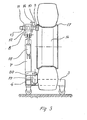
- FIG 3 is a section at A-A in FIG 2.
- FIG 4 is a partial view illustrating a modified embodiment.
- FIG 5 is a section B-B in FIG 4.
- FIG 6 is a partial view illustrating yet a further modified embodiment.
- FIG 7 is a section C-C in FIG 6.
- The arrangement shown in the diagrams consists of an essentially horizontal, U-shaped rigid frame 1 having two
free limbs 2 and 3 which are parallel with each other, and which are rigidly connected with each other by means of theframe girder 4. The frame 1 is designed so that thelimbs 2 and 3 can straddle avehicle wheel 5 resting on the sub-surface, where the side of the wheel faces towards and is essentially parallel with theframe girder 4. The distance between thelimbs 2 and 3 of frame 1 is hence adapted to suit the largest wheel dimension for which the arrangement is to be employed. The frame 1 is supported on the horizontal sub-surface by means of four wheels or rollers, preferably four swivel rollers 6, which can swivel around vertical axes so that the frame 1 can easily be moved on the sub-surface in any required direction. - On one side frame 1 carries a
vertical pedestal 7 which at the top is hinge-connected with anarm 8 which can swivel in a plane parallel with theframe girder 4. At its free end thearm 8 carries a supportingroller 9 which can rotate around an axis which is parallel with the axis of rotation of thevehicle wheel 5..The support- -ing roller 9 which is preferably mounted in ball bearings, is mounted at the end of abar 10 which extends at right angles to thearm 8 and which can be displaced inside asleeve 11 welded into thearm 8 and which projects a certain distance on either side of the said arm. A throughhole 12 of the same dimension as a series ofholes 13 in thebar 10 is provided in each of the sections of thesleeve 11 which project on either side of thearm 8. By means of alocking pin 14 which is introduced through thehole 12 on one side of thesleeve 11 and any of theholes 13 in thebar 10, the supportingroller 9 can thus be fixed at a distance from thearm 8 selected in accordance with the series of holes. - The supporting
roller 9 is provided with twoflanges 15 so that a groove is formed between the flanges. The groove in the supportingroller 9 is designed so as to interact with a rail 17 arranged on therim 16 of thevehicle wheel 5 and which is centered around the axis of rotation of the rim, and which in the example shown in FIGS.1 - 3 is formed by the edge of the rim which is bent over towards the wheel axis. Thus, when engaged with the rail 17 the supportingroller 9 prevents axial movement of therim 16 and thus of thevehicle wheel 5 at the point of engagement of theroller 9 with the rim. - The
arm 8 can swivel in the vertical plane by means of a device exercising force, e.g. a hydraulic cylinder or ajack 18. When a medium under pressure is supplied to thehydraulic cylinder 18, thearm 8 is made to swivel around its swivel axis on thepedestal 7. When the supportingroller 9 is in engagement with therim 16, this swivelling.movement causes the vehicle wheel to be lifted from its sub-surface. To support the vehicle wheel laterally during this two supportingrollers 19 are mounted inholders 20 on theframe girder 4. The axes of rotation of therollers 19 extend at right angles to the axis of the vehicle wheel and form an angle with each other. Preferably, the angle formed by the supporting rollers in respect of a vertical plane of symmetry to the frame is about 20°. - When a
vehicle wheel 5 is to be fitted, the accessory is placed in position close to the wheel with thelimbs 2 and 3 in front of respectively behind thewheel 5 and with the supportingrollers 19 in contact with the tyre side of the vehicle wheel. Thearm 8 is set in such a position that the supportingroller 9 located on thebar 10 is within the free space in therim 16 with the groove on the supporting roller in the centre of the rail 17 in the rim. By supplying medium under pressure to thehydraulic cylinder 18, using a hydraulic hand pump which is not illustrated, thearm 8 is made to swivel until its supportingroller 9 has engaged with the rail 17 on therim 16. The swivel movement of the arm continues until thevehicle wheel 5 is raised from the sub-surface. As a result thewheel 5 is raised whilst being suspended stably on the supportingroller 9 and with the smooth tyre side of the wheel resting against the two supportingrollers 19. - The accessory is then moved, rolling on the sub-surface, up to the vehicle on which the wheel is to be fitted. The alignment of the
wheel 5 laterally in relation to the hub is undertaken by moving the frame to the required extent on the sub-surface. Vertical alignment is accomplished by raising or lowering thearm 8, and thus thewheel 5 which hangs in the supportingroller 9. After the wheel has been centered in relation to the centre of the hub or rim plate, the wheel which hangs on supportingroller 9 is rotated to the necessary extent so that the bolt holes in the rim correspond with the hub bolts, after which the rim nuts are screwed up tight. Since the ball-bearing-mounted supportingroller 9 runs easily against therail 19 in therim 16, twisting of the wheel requires only a small amount of force and can be undertaken using one hand. During rotation the centre position of the wheel is maintained, because the rail 17 is centered around the axis of rotation of the wheel. Thanks to the fact that thepedestal 7 is arranged on one side of the frame 1, the area around the rim is left free, so that fitting operations can be executed with the maximum possible accessibility. Throughout the entire working operation the vehicle wheel rests stably on the supportingroller 9 with the tyre side resting against the supportingrollers 19 on theframe girder 4. After the rim nuts have been tightened up, the pressure in thehydraulic cylinder 18 is released, so that thearm 8 swivels downwards and the supportingroller 9 is disengaged from the rail 17 on therim 16, after which the accessory is rolled away from under the vehicle. - When moving a vehicle wheel, the operations described above are performed appropriately, but in the reverse order.
- In the embodiment described above the rim of the vehicle wheel has been assumed to be of the type where the edges of the rim have already, during manufacture, been bent over towards the centre of rotation of the wheel so that a rail centered around the axis of rotation of the rim is obtained, this being used in the manner described above as a holding point so as to provide permanent engagement between the supporting roller and the vehicle wheel. Other types of rims available on the market are so designed that the said rail 17 is lacking. To be able to employ the arrangement in accordance with the present invention for fitting and removal of wheels with rims of the latter-mentioned type, the rim'can be provided with a holding point, e.g. by welding on or fastening in some other way, a flange or
rail 21 to the rim, as illustrated in FIGS 4 and 5. The flange orrail 21 does not need to extend around the entire periphery of therim 16. It is sufficient if the arc-shaped rail 21 covers so large a portion of the circumference of therim 16 that the vehicle wheel can be twisted through so large an angle that the bolt holes in the rim are aligned centrally with the hub bolts in the wheel hub. Therail 21 should preferably be provided with astop lug 22 at each end so as to prevent the supportingroller 9 from rolling off therail 21. With this arrangement therail 21 is placed further within therim 16 than is the case when the holding point comprises the bent over edge of the rim. As a result of the fact that thebar 10 which carries the supportingroller 9 can be displaced and is adjustable in various projection positions, this facilitates simple adjustment of the projecting length which is required to locate the supportingroller 9 in a central position in'respect of therail 21 when the location of the latter varies. - The adjustment of the supporting
roller 9 in the axial direction can as an alternative be undertaken infinitely-variably by arranging for the projection of thebar 10 to be brought about instead by means of a mechanical or hydraulic force device, e.g. a screw arrangement. Thebar 10 can for example be designed as a screw which at one end carries the supportingroller 9 whilst its opposite end is provided with a crank for rotating the screw in the bearing provided with a suitable thread in thearm 8. - FIGS 6 and 7 show a further embodiment which has been modified so as to ensure absolutely safe fitting and removal of large vehicle wheels, regardless of whether the rim is provided with a holding point as described in conjunction with FIGS 1 - 5, or if the rim has no holding point whatever.
- The modified arrangement differs from the embodiments previously described in that a
holding point 23 is arranged on thearm 8 instead of in the rim, whereby theholding point arrangement 23 can be made to engage with the side of the tyre which faces away from thearm 8, thus preventing thewheel 5 from sliding off the supportingroller 9. Theholding point arrangement 23 consists of asleeve 24 with square cross section, e.g. a square tube, welded onto the arm in the vicinity of the bearingsleeve 11 for the supportingroller 9, and extending vertically at right angles to thearm 8. Asquare bar 25, preferably a square tube, the upper end of which has a bearingsleeve 26 gripped at right angles to thebar 25 is arranged in thesleeve 24 and capable of vertical movement. Around bar 27 which can move in a direction parallel to the axis of rotation of thewheel 5, i.e. transverse to the wheel, is arranged in the bearingsleeve 26. Theround bar 27 can also rotate around its own axis in the bearingsleeve 26 and its far end has been bent over about 90 towards the axis of rotation of thewheel 5. Aroller 29, which can easily rotate, preferably consisting of a ball bearing, is mounted at the end of the bent-overportion 28. By displacing and twisting theround bar 27 in the bearingsleeve 26 theroller 29 can be made to rest against the outside of the tyre. To facilitate the displacement and turning movement, the round bar is provided with ahandle 30. Both the bearingsleeve 26 and thesleeve 24 are provided withdetent screws holding point arrangement 23, after the necessary vertical and lateral adjustment, can be locked into the set position. The length of thebar 25 andround bar 27 are selected so that the necessary adjustments are possible for all wheel dimensions for which the accessory is designed to be used. - When a wheel is to be placed in the accessory, the
holding point arrangement 23 is so adjusted that theround bar 27 withroller 29 does not touch the tyre when the supporting roller is placed in the engaged position with the rim. Then theround bar 27 is twisted so that its bent-overportion 28 faces the axis of rotation of the wheel, after whichroller 29 is made to rest against the outside of the tyre. - After the
holding point arrangement 23 has been fixed in the set position by means of the detent screws 31, 32 thewheel 5 is lifted by means of the supportingroller 9 in the manner described previously. The accessory can then be moved along the sub-surface with the wheel 5- hanging from the supportingroller 9, during which the holding point arrangement prevents thewheel 5 from sliding off the supporting roller. - The alignment of the
wheel 5 in relation to the hub bolts or other fastening devices can then be performed in the manner previously described. After the wheel has been fastened in position the holding point arrangement is adjusted so that the accessory can be freely withdrawn from under the wheel, after the supportingroller 9 has been disengaged from the rim by lowering thearm 8. - In the embodiments shown in FIGS 1 - 5 the supporting
roller 9 is provided with two flanges which together with the supporting surfaces of the supporting roller form a circular groove. If the edge of the rim is so designed that a circular, e.g. V-shaped groove is formed in the side of the rim, the supportingroller 9 can be provided with a profile which corresponds to the shape of the rim groove, e.g. V-shaped, whereby the supportingroller 9 is designed without flanges. This form of supporting roller can also be employed with the embodiment shown in FIGS 6 and 7, as shown by FIG 7. Other forms of supporting roller peripheral surface can also be envisaged. Thus, the roller can be designed with a sharp, lip-shaped side or be provided with a friction covering e.g. in the form of one or more 0-rings arranged in grooves in the supporting surface of the supporting roller. The supportingroller 9 can be appropriately provided with replaceable supporting rings of different profiles which can be fastened to the hub of the supporting roller by means of a simple screw connection.
Claims (10)
1. Arrangement for facilitating the fitting and removal of .large vehicle wheels, e.g. rim-mounted pneumatic tyred wheels for tractors, trucks or the like, comprising a frame (1) which can move on an essentially horizontal sub-surface, having two free limbs (2, 3) the said frame (1) supporting a pedestal (7) which is provided with devices for retaining engagement with a vehicle wheel (5), located between the free arms of the frame, characterised in that the said device for engagement with the wheel (5)comprises a supporting roller (9) which is supported by the pedestal (7) and movable by force in the vertical direction, the said supporting roller being rotatable around an axis essentially parallel with the axis of rotation of the wheel (5) and so arranged that in rolling interaction with the rim it permits rotation of the wheel around its axis of rotation whilst at the same time supporting the wheel.
2: Arrangement as claimed in claim 1, characterised in that two supporting rollers (19) for supporting the wheel (5) by contact between the tyre side of the wheel and the said supporting rollers.which are transverse relative to the axis of the supporting roller(9)are mounted on the frame.
3. Arrangement as claimed in claim 1 or 2, characterised in that the supporting roller-(9) is so designed as to interact with a holding point (21) arranged on the rim (16) and prevent axial movement of the wheel at the point of engagement of the supporting roller (9) with the rim.
4. Arrangement as claimed in any of claims 1 - 3, characterised in that the pedestal (7) is located on the frame (1) at one side and supportsan arm (8) which can be swivelled by means of a force device (18) relative to the pedestal, and which in turn carries the said supporting roller (9).
5. Arrangement as claimed in any of claims 1 - 4, characterised in that the supporting roller (9) is rotatably mounted at the end of a bar (10) which is supported by the said arm (8), and which is displaceable in the axial direction of the supporting roller relative to the arm (8).
6. Arrangement as claimed in claim 5, characterised in that the displacement movement of the bar (10) is brought about by means of a screw arrangement.
7. Arrangement as claimed in claim 6, characterised in that the bar (10) comprises a screw supported by the arm (8) in a threaded through hole in the arm.
8. Arrangement as claimed in any of claims 3 - 6, characterised in that the said holding point comprises the side of the rim (16) which is bent over towards the centre axis of the rim.
9. Arrangement as claimed in any of claims 3 - 6, characterised in that the said holding point comprises a flange (21) fastened into the rim (16).
10. Arrangement as claimed in claim 9, characterised in that the said flange (21) extends over only a portion of the circumference of the rim.
Applications Claiming Priority (2)
| Application Number | Priority Date | Filing Date | Title |
|---|---|---|---|
| SE8006231A SE434034B (en) | 1980-09-08 | 1980-09-08 | DEVICE FOR EASY TO ASSEMBLY AND REMOVE LARGE VEHICLE WHEELS |
| SE8006231 | 1980-11-18 |
Publications (2)
| Publication Number | Publication Date |
|---|---|
| EP0052586A2 true EP0052586A2 (en) | 1982-05-26 |
| EP0052586A3 EP0052586A3 (en) | 1983-04-06 |
Family
ID=20341679
Family Applications (1)
| Application Number | Title | Priority Date | Filing Date |
|---|---|---|---|
| EP81850203A Withdrawn EP0052586A3 (en) | 1980-09-08 | 1981-10-30 | Device for facilitating the mounting and dismounting of large vehicle wheels |
Country Status (2)
| Country | Link |
|---|---|
| EP (1) | EP0052586A3 (en) |
| SE (1) | SE434034B (en) |
Cited By (13)
| Publication number | Priority date | Publication date | Assignee | Title |
|---|---|---|---|---|
| DE3917639A1 (en) * | 1989-05-31 | 1990-12-06 | Ahlmann Maschinenbau Gmbh | Mounting heavy large dia. vehicle wheel - with post-like support with holder for wheel and smooth surface against which tyre rests |
| WO1992012864A1 (en) * | 1991-01-23 | 1992-08-06 | Auto-Jure Oy | Device for handling vehicle wheel |
| DE19535380A1 (en) * | 1995-09-25 | 1997-03-27 | Kunz Gmbh | Rim and tyre manipulating device |
| DE10059541A1 (en) * | 2000-11-30 | 2002-06-13 | Josef Kiening | Carrying and transporting device for wheel of tractor or similar vehicle, comprising adjustable fixing element and lifting unit |
| WO2006078784A3 (en) * | 2005-01-18 | 2007-11-29 | Android Ind Llc | A system for transporting and manipulating tires and wheels |
| US8365794B2 (en) | 2005-01-18 | 2013-02-05 | Android Industries Llc | Inflation work station |
| DE102011117669A1 (en) * | 2011-11-03 | 2013-05-08 | Eberhard Röhlich | Wheel mounting aid for motor car and trailer, has centrally arranged operation spindle performing plan parallelism between hub and rim, and rotatable wheel retainer rotated to perform alignment of set of mounting holes |
| US8701736B2 (en) | 2005-01-18 | 2014-04-22 | Android Industries Llc | Inflation work station |
| US9174829B2 (en) | 2013-10-04 | 2015-11-03 | Mvp (Hk) Industries, Inc. | Adjustable wheel rack |
| DE102017114819A1 (en) * | 2017-07-04 | 2019-01-10 | Karin Thewes | Multifunction lifting device |
| CN111016557A (en) * | 2018-10-10 | 2020-04-17 | 巴特勒工程及营销股份公司 | Machine for mounting and/or demounting vehicle wheels, in particular truck wheels |
| CN113650450A (en) * | 2021-08-27 | 2021-11-16 | 东风柳州汽车有限公司 | A lightweight aluminum alloy wheel for a truck |
| CN117067819A (en) * | 2023-09-18 | 2023-11-17 | 杭州中车车辆有限公司 | A method for changing wheels of a monorail vehicle |
Family Cites Families (4)
| Publication number | Priority date | Publication date | Assignee | Title |
|---|---|---|---|---|
| US2543276A (en) * | 1946-03-18 | 1951-02-27 | Buechler George Fred | Tire handling device |
| US2792139A (en) * | 1955-03-07 | 1957-05-14 | Thomas W Lloyd | Portable wheel-assembly hoist |
| US3321147A (en) * | 1965-08-24 | 1967-05-23 | Merrill D Martin | Pick-up roll stand |
| US3653527A (en) * | 1970-11-03 | 1972-04-04 | George R Clapp | Vehicle wheel dolly |
-
1980
- 1980-09-08 SE SE8006231A patent/SE434034B/en unknown
-
1981
- 1981-10-30 EP EP81850203A patent/EP0052586A3/en not_active Withdrawn
Cited By (24)
| Publication number | Priority date | Publication date | Assignee | Title |
|---|---|---|---|---|
| DE3917639A1 (en) * | 1989-05-31 | 1990-12-06 | Ahlmann Maschinenbau Gmbh | Mounting heavy large dia. vehicle wheel - with post-like support with holder for wheel and smooth surface against which tyre rests |
| WO1992012864A1 (en) * | 1991-01-23 | 1992-08-06 | Auto-Jure Oy | Device for handling vehicle wheel |
| AU660298B2 (en) * | 1991-01-23 | 1995-06-22 | Auto-Jure Oy | Device for handling vehicle wheel |
| US5464314A (en) * | 1991-01-23 | 1995-11-07 | Auto-Jure Oy | Device for handling a vehicle wheel |
| DE19535380A1 (en) * | 1995-09-25 | 1997-03-27 | Kunz Gmbh | Rim and tyre manipulating device |
| DE10059541A1 (en) * | 2000-11-30 | 2002-06-13 | Josef Kiening | Carrying and transporting device for wheel of tractor or similar vehicle, comprising adjustable fixing element and lifting unit |
| WO2006078784A3 (en) * | 2005-01-18 | 2007-11-29 | Android Ind Llc | A system for transporting and manipulating tires and wheels |
| EP1841606A4 (en) * | 2005-01-18 | 2009-01-07 | Android Ind Llc | A system for transporting and manipulating tires and wheels |
| US7845655B2 (en) | 2005-01-18 | 2010-12-07 | Android Industries Llc | System for transporting and manipulating tires and wheels |
| US8176960B2 (en) | 2005-01-18 | 2012-05-15 | Android Industries Llc | System for transporting and manipulating tires and wheels |
| CN101176086B (en) * | 2005-01-18 | 2012-06-27 | 安德罗伊德工业有限公司 | Systems for conveying and handling tires and wheels |
| US8365794B2 (en) | 2005-01-18 | 2013-02-05 | Android Industries Llc | Inflation work station |
| US9440503B2 (en) | 2005-01-18 | 2016-09-13 | Android Industries Llc | Inflation work station |
| US8701736B2 (en) | 2005-01-18 | 2014-04-22 | Android Industries Llc | Inflation work station |
| US10065463B2 (en) | 2005-01-18 | 2018-09-04 | Android Industries Llc | Inflation work station |
| DE102011117669A1 (en) * | 2011-11-03 | 2013-05-08 | Eberhard Röhlich | Wheel mounting aid for motor car and trailer, has centrally arranged operation spindle performing plan parallelism between hub and rim, and rotatable wheel retainer rotated to perform alignment of set of mounting holes |
| US9174829B2 (en) | 2013-10-04 | 2015-11-03 | Mvp (Hk) Industries, Inc. | Adjustable wheel rack |
| DE102017114819A1 (en) * | 2017-07-04 | 2019-01-10 | Karin Thewes | Multifunction lifting device |
| DE102017114819B4 (en) | 2017-07-04 | 2021-07-22 | Karin Thewes | Multifunctional lifting device |
| CN111016557A (en) * | 2018-10-10 | 2020-04-17 | 巴特勒工程及营销股份公司 | Machine for mounting and/or demounting vehicle wheels, in particular truck wheels |
| CN111016557B (en) * | 2018-10-10 | 2023-05-12 | 巴特勒工程及营销股份公司 | Machine for mounting and/or dismounting vehicle wheels, in particular truck wheels |
| CN113650450A (en) * | 2021-08-27 | 2021-11-16 | 东风柳州汽车有限公司 | A lightweight aluminum alloy wheel for a truck |
| CN113650450B (en) * | 2021-08-27 | 2023-05-30 | 东风柳州汽车有限公司 | Lightweight aluminum alloy wheel for trucks |
| CN117067819A (en) * | 2023-09-18 | 2023-11-17 | 杭州中车车辆有限公司 | A method for changing wheels of a monorail vehicle |
Also Published As
| Publication number | Publication date |
|---|---|
| SE434034B (en) | 1984-07-02 |
| SE8006231L (en) | 1982-05-19 |
| EP0052586A3 (en) | 1983-04-06 |
Similar Documents
| Publication | Publication Date | Title |
|---|---|---|
| EP0052586A2 (en) | Device for facilitating the mounting and dismounting of large vehicle wheels | |
| US3830387A (en) | Vehicle wheel handling apparatus | |
| US5269501A (en) | Vehicle and vehicle parts transportation system | |
| US5064334A (en) | Wheel clamp | |
| US5176487A (en) | Vehicle wheel changing tool | |
| US4571142A (en) | Mechanism for lifting vehicle tires | |
| EP3645212B1 (en) | An apparatus for supporting a heavy vehicle brake assembly | |
| EP1189798B1 (en) | Apparatus for supporting automotive tires | |
| US4597711A (en) | Device to facilitate changing tires | |
| US5378004A (en) | Device for removing brake drum and hub assembly | |
| JPH05154998A (en) | Rotary printing machine and workshop trolley | |
| US4550835A (en) | Tire changing rack | |
| US5257446A (en) | Method to rotate tire and wheel assemblies | |
| US4971511A (en) | Vehicle lifting device | |
| CA1106275A (en) | Tire changing apparatus | |
| EP0659597B1 (en) | For tyre removal machines in general, a device for facilitating the removal and the mounting of tyres from and onto respective wheel rims | |
| CN217071553U (en) | An anti-drop-off clamping mechanism | |
| JPH01132401A (en) | Tire conveyor | |
| CA2168316C (en) | Lifting and swivelling device, in particular for motor vehicles | |
| CN217582058U (en) | Upper buckling frame of well drilling lifting joint | |
| US4830335A (en) | Portable jack | |
| CA1308141C (en) | Wheel clamp | |
| SE464626B (en) | Device pertaining to an assembly tool for facilitating assembly, disassembly and transport of large vehicle wheels, especially with rough tyre pattern | |
| GB2266281A (en) | Wheel changing trolley. | |
| WO1999002444A1 (en) | Vehicle tilting carriage |
Legal Events
| Date | Code | Title | Description |
|---|---|---|---|
| PUAI | Public reference made under article 153(3) epc to a published international application that has entered the european phase |
Free format text: ORIGINAL CODE: 0009012 |
|
| AK | Designated contracting states |
Designated state(s): DE FR GB IT NL |
|
| PUAL | Search report despatched |
Free format text: ORIGINAL CODE: 0009013 |
|
| AK | Designated contracting states |
Designated state(s): DE FR GB IT NL |
|
| STAA | Information on the status of an ep patent application or granted ep patent |
Free format text: STATUS: THE APPLICATION IS DEEMED TO BE WITHDRAWN |
|
| 18D | Application deemed to be withdrawn |
Effective date: 19831207 |