EP0052542B1 - Electrochemical sensor for trace gases in a fluid-mixture, and regulation system of the air-fuel ratio in an air-fuel mixture using such a sensor - Google Patents
Electrochemical sensor for trace gases in a fluid-mixture, and regulation system of the air-fuel ratio in an air-fuel mixture using such a sensor Download PDFInfo
- Publication number
- EP0052542B1 EP0052542B1 EP81401648A EP81401648A EP0052542B1 EP 0052542 B1 EP0052542 B1 EP 0052542B1 EP 81401648 A EP81401648 A EP 81401648A EP 81401648 A EP81401648 A EP 81401648A EP 0052542 B1 EP0052542 B1 EP 0052542B1
- Authority
- EP
- European Patent Office
- Prior art keywords
- region
- reactive species
- electrode
- probe
- admitted
- Prior art date
- Legal status (The legal status is an assumption and is not a legal conclusion. Google has not performed a legal analysis and makes no representation as to the accuracy of the status listed.)
- Expired
Links
Images


Classifications
-
- G—PHYSICS
- G01—MEASURING; TESTING
- G01N—INVESTIGATING OR ANALYSING MATERIALS BY DETERMINING THEIR CHEMICAL OR PHYSICAL PROPERTIES
- G01N27/00—Investigating or analysing materials by the use of electric, electrochemical, or magnetic means
- G01N27/26—Investigating or analysing materials by the use of electric, electrochemical, or magnetic means by investigating electrochemical variables; by using electrolysis or electrophoresis
- G01N27/403—Cells and electrode assemblies
- G01N27/406—Cells and probes with solid electrolytes
- G01N27/407—Cells and probes with solid electrolytes for investigating or analysing gases
- G01N27/4071—Cells and probes with solid electrolytes for investigating or analysing gases using sensor elements of laminated structure
-
- G—PHYSICS
- G01—MEASURING; TESTING
- G01N—INVESTIGATING OR ANALYSING MATERIALS BY DETERMINING THEIR CHEMICAL OR PHYSICAL PROPERTIES
- G01N27/00—Investigating or analysing materials by the use of electric, electrochemical, or magnetic means
- G01N27/26—Investigating or analysing materials by the use of electric, electrochemical, or magnetic means by investigating electrochemical variables; by using electrolysis or electrophoresis
- G01N27/416—Systems
- G01N27/417—Systems using cells, i.e. more than one cell and probes with solid electrolytes
Definitions
- the invention relates to electrochemical sensors for the concentrations of species in a fluid mixture and in particular to a system for regulating the richness of a gaseous air-fuel mixture.
- Recent approaches for producing sensors propose the use of a means combining the electrode function and the reference medium function.
- an electrode based on a combination of the type is used: M-MX where M is a metal and X is oxygen or a halogen to be detected (for example M-MO in the case of detection of the oxygen).
- M-MX an electrode based on a combination of the type
- X oxygen or a halogen to be detected
- sensors have also been proposed produced according to the thin film technique used in microelectronics.
- the invention relates to sensors of the type comprising electrodes or other means placed upstream of the electrochemical measurement cell carrying out the complete catalysis, so that the gas mixture to be analyzed reaches thermodynamic equilibrium at least at the electrode-electrolyte interface and one of the electrodes of which is of the type described above based on an M-MX combination.
- Such sensors are commonly used for regulating internal combustion engines and in particular for regulating the admission of the air-fuel mixture to the carburetor or the fuel injector.
- the sensor is then placed in the exhaust circuit and analyzes the relative concentration of the oxygen-carbon monoxide species contained in the gas.
- the sensor must then be adapted to certain characteristics specific to this use. Indeed the exhaust gas will arrive in jerks, at the rate of the reciprocating movement of the different pistons.
- the electrode is in the form of a layer of porous catalyst material and the gas to be analyzed propagates within it in a direction parallel to the largest dimensions of the electrode before reaching the actual measurement area.
- a sensor is described in European patent applications EP-A-00110 38 and EP-A-0-012647.
- sensors can be used as they are in certain countries, in particular in countries imposing strict anti-pollution standards.
- the engine then operates with a stoichiometric air-fuel mixture.
- the "transfer impedance" as defined above is made selective by the use of a porous material specially adapted to the fluid to be analyzed.
- a mixture composition given at the input of the sensor can correspond to a different mixture composition within the porous material and then at the level of the measurement electrode.
- the apparent concentration of the species of a gas mixture is measured, that is to say that which exists at the level of the measurement electrode, and by this the regulation point is shifted on either side of the stoichiometry of the gaseous mixture actually circulating in the exhaust ducts.
- a regulation system using this type of sensor is less dependent on the effects of temperature since in this case the tilting of the response curve is also detected. , tilting which occurs on either side of the stoichiometry according to the nature 1 "'transfer impedance", ie in a region of the curve less sensitive to this parameter.
- the amplitude of the offset allowed by these devices is relatively limited and fixed once all at a predetermined value at the time of manufacture.
- the invention aims to fill this need by using a sensor structure incorporating a member of the ion pump type making it possible to continuously change the concentration. apparent relative measured at the measurement electrode, using an electronic control current.
- This type of organ is used in the known art to regulate the concentration of a chemical species in an enclosure or a pipe, for example oxygen, by carrying out a reversible pumping of this species contained in a second reservoir enclosure.
- An ion pump generally has a structure analogous to that of an electrochemical cell: a membrane constituted by a solid electrolyte permeable to ions of the chemical species to be "pumped" comprising on its two faces electrodes connected to the terminals of a source of electronic current. Depending on the amplitude and the polarity of the current, an ion current is established within the electrolyte resulting in the transport of ions of the species which recombine on one of the two electrodes according to the direction of conduction. In the case of oxygen, the relation (1) previously recalled is satisfied.
- Such ion pumps are also used in devices for measuring the quantity of oxygen included in a sample of a gaseous mixture admitted into a measurement enclosure.
- the method used consists in separating the oxygen from the other chemical species included in the mixture. To do this, the ion pump pumps oxygen out of the enclosure through a solid ionic conductor of oxygen ion.
- the amount of oxygen present in the gas mixture can be determined by measuring the amount of electrical charge supplied to the ion pump to extract this oxygen from the enclosure.
- Measuring devices of this type are also provided with an electrochemical measurement cell measuring a low oxygen concentration in the measurement enclosure. This measurement is carried out by detecting a large potential difference across the terminals of the measurement cell of determined amplitude.
- the subject of the invention is therefore an electrochemical sensor as specified in claims 1 or 3.
- the subject of the invention is also a system for regulating the richness of the air-fuel mixture of a combustion engine using a sensor as specified in claims 1 to 11, said system being defined in claim 12.
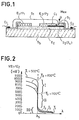
- FIG. 1 describes an example of a sensor structure of the prior art, simultaneously incorporating the functions of "test portion", of catalysis and of measurement proper and produced according to the deposition techniques in thin layer or in thick layer.
- test portion of catalysis
- measurement proper produced according to the deposition techniques in thin layer or in thick layer.
- electrochemical sensors described are intended for the detection of the relative concentrations of oxygen and carbon monoxide, without this being limiting the scope of the invention.
- the main characteristics of such a sensor will be recalled in the following by way of illustration of the known art.
- the sensor of FIG. 1 comprises two electrodes deposited on a solid electrolyte E, itself deposited on the substrate Sb.
- the electrodes E 1 / P 1 and E 2 are located in the same plane.
- the E 1 / P 1 electrode combines the functions of electrode and reference medium.
- the electrode E 1 / P j is further protected from the external environment by a waterproof and inert insulator S 1 , which covers it. An association of the Ni / Ni 0 type can be used to produce this reference electrode-medium.
- the electrode E 2 has two zones and communicates directly with the medium to be analyzed Mex in which the gas mixture G circulates through an orifice made in the insulating body S 1 which also covers it.
- the electrode In the first zone Ct, the electrode is isolated on its underside from the electrolyte E l by an insulating body S 2 of the same type as S 1 , over a length 1 c .
- the fluid to be analyzed must pass through the body C t which is a catalyst.
- the reactive species of the mixture to be analyzed (for example, in the case of exhaust gases: CO and O 2 ) are brought to complete thermodynamic equilibrium before they reach the electrochemical cell proper:
- the area C t is not that the extension of the electrode E 2 / P 2 and consists of the same material, for example platinum, deposited in a thin layer.
- the catalysis is carried out by the fluid passing through the catalyst in a direction parallel to the plane of the electrodes.
- the electrodes are extended towards the outside by metal connections on which the contacts Ci and C 2 can be welded, connections which are produced in platinum lacquer for example.
- the substrate S b can be constituted by a good insulator at the operating temperature of the device (corundum for example) and ensures the mechanical strength of the assembly. This substrate can be extended in any direction to be adapted to means for fixing to a housing.
- the solid electrolyte can consist of a thick plate and the substrate does not exist.
- Deposits can be carried out by well-known techniques, such as: vacuum deposition (sputtering, evaporation), vapor deposition, electrochemical deposition or ion implantation or by a combination of two or more of these techniques.
- FIG. 2 illustrates a set of response curves of the oxygen concentration sensors of the prior art in the exhaust gases of an internal combustion engine.
- Each curve represents the difference in inter-electrode potential V E1 / E2 as a function of the concentration of oxygen in the exhaust gases, at constant temperature.
- zones 1 and III the different curves are clearly differentiated from each other. Indeed, if we refer to the relations (2) and (4) recalled above, we note that these relations both contain the parameter "absolute temperature T". It is therefore difficult to exploit these parts of the curves, because the exhaust gases do not have a constant temperature.
- zone II of FIG. 2 which corresponds to the tilting, the different curves are practically combined. Also only this area is usually exploited.
- the output of the sensor is transmitted to an electrical control member (not shown) which detects the rapid tilting of the curve V E1 / E2 around the abscissa point ⁇ s , which represents the stoichiometric ratio of the mixture, as it is measured at the measuring electrode E 2 / P 1 .
- the tipping point is fixed, even if it is possible by the method described in the above-mentioned European patent application EP-A-0011530 to shift this tipping point slightly on either side of the stoichiometry.
- the structure of the sensor incorporates an additional cell analogous to the measurement cell E 1 -E 1 -E 2 operating as an ion pump, and which will be called in the following ion pumping cell.
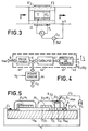
- a tell ion pump is described schematically in Figure 3. It is substantially in the form of an electrochemical cell comprising a solid electrolyte E, the ion conductor of at least one specific chemical species, for example oxygen, annular shape in the example chosen on the inner and outer faces of which has been deposited a pair of electrodes, E 1 'and E 2 ' respectively.
- an ion current is created within the electrolyte, that is to say a transport of ions of the species considered from the electrode E 2 'to the electrode E 1 ' or vice versa, the amplitude of this ion current being linked by a determined law to the amplitude of the control voltage V c .
- the electrodes must be porous or permeable to the determined chemical species.
- the example of oxygen will be considered in what follows, it being understood that the oxygen can be pure or be included in a mixture of various fluids.
- the ion current within the electrolyte results in an electronic current i in the electrical circuit outside the cell. The current i can deduce from the above relation (1).
- the cell develops an own counter-electromotive force V E1 / E2 given by the law of NERNST and explained by the relation (2).
- Z el is the impedance of the solid electrolyte E, 'opposing the ionic conduction which is reduced as a first approximation to a resistance R el which depends on the characteristics dimensions of the solid electrolyte and its ionic conductivity at a given temperature.
- P 1 and P 2 are the partial pressures of media 1 and II respectively
- medium II can be considered as a reservoir medium containing at least oxygen
- medium I the medium in which a gas mixture circulates, the oxygen concentration of which must be regulated.
- a gas mixture G circulates in a pipe, passes through the enclosure 1 formed by the interior of the ion pump and leaves in the form of a gas mixture G 'with an oxygen concentration modified by the ion pump.
- an electrochemical measurement sensor S is placed at the output, measuring the concentration of the mixture at output G '.
- the electrical signals are transmitted to a comparator Co which receives on a second input a reference value Ref so as to act on the control voltage Vo and by the same fact on the current i, in amplitude and in polatire.
- the invention proposes a sensor comprising two electrochemical cells.
- the first cell detecting the stoichiometry of a small volume of gas mixture which is transmitted to it after catalysis, this small volume of gas mixture coming from a "test sample”.
- the second cell is an ion pump and modifies the composition of the gas mixture admitted inside the sensor so that the output signal V E1 / E2 of the measurement cell has a tilting for a value different from the stoichiometry of the gas mixture as it actually appears at the sensor inlet (Mex).
- Figure 4 schematically illustrates the operation of a sensor according to the invention.
- the three functions common to the sensors of the known art for example the sensor described in relation to FIG. 1: "test sample” 41, "catalysis” 42 and “measurement cell” 43 , these functions being able to be entirely or partly carried out by a common body.
- the composition of the gas mixture G ′ after test portion in the known art, being identical to or very close to the composition of the gas mixture in the external environment Mex where the mixture to be measured circulates. Before measurement, the gas mixture G "checks the relation (4).
- the ion pumping cell 44 using a control voltage V c , makes it possible to continuously modify the composition of the admitted gas mixture G 'by injecting or removing oxygen.
- test portion function can be carried out in different ways: using a calibrated orifice, an inert porous body or, in the case of sensors analogous to that of FIG. 1, using the catalyst body itself Ci extending the measuring electrode E 2.
- these functions correspond to regions of the sensor which cannot in general be distinguished in such a way clear, a single organ can perform all or part of these functions by itself.
- Ion pumping can be carried out at any point between the measurement cell and the test sample area, that is to say most often in the catalysis zone.
- This latter structure is particularly advantageous since it simultaneously allows good measurement sensitivity and a small quantity of gas admitted: of the order of mm 3 / s for example between 0.5 and 5 mm 3 / s; this in addition to the technological advantages due to the use of production techniques in thin or thick layers. It is therefore possible to significantly modify the oxygen composition of the admitted mixture G 'inside the sensor without requiring a large ion current within the solid electrolyte of the ion pumping cell, that is to say of the voltage of control V o or what amounts to the same of current i.
- FIG. 5 illustrates in section a first alternative embodiment of sensors according to the invention, according to a first approach.
- an additional electrochemical cell is integrated in the sensor and comprises a solid electrolyte E 12 inserted between two electrodes E 3 and E4.
- the second electrode E4 is merged with the extension of the measurement electrode E 2 .
- the assembly filling a channel pierced in the insulating envelope.
- the cell is exposed on the surface of the insulator S 1 so as to communicate with an oxygen-containing medium, this medium possibly being the Mex medium in which the gas mixture to be analyzed circulates G.
- the cell E 3 E 12 -E 4 is supplied by a control current i via the connections C 3 and C 4 , C 4 being merged with C 2 .
- FIG. 6 represents a practical embodiment in which the electrolyte E 12 is in the form of a layer or a plate attached or deposited on the extension of the measurement electrode. Then the enamel coating is deposited. The opening revealing the electrolyte E, 2 can be produced by masking and the electrode E 3 is then deposited. This electrode can be produced using a platinum lacquer.
- the electrolyte can easily be placed at the end of the substrate near the test sample area P es as illustrated in FIG. 7. This arrangement avoids providing an orifice in the enamel layer S,.
- the electrolyte can also be arranged in the form of a screen-printed layer as illustrated in FIG. 8.
- FIG. 10 more specifically illustrates the case where the electrolyte is deposited by screen printing as in the case of FIG. 8.
- the electrode e4 was merged with the extension of the measurement electrode. According to a second approach, three variants of which are illustrated in relation to the figures 11 to 13, the electrode E4 can be separate and the ion pumping cell E 2 -E 12 -E 4 appear as an element attached to the protective enamel. S 1 .
- the "test portion" area Pas is in the form of a calibrated orifice, similar to those used in certain types of sensors of the known art, limiting predetermined amount of gas mixture admitted to the interior of the sensor, that is to say in an enclosure underlying the ion pumping cell in which the composition of the gas mixture is modified and becomes G ′, this due to the action of this cell.
- This enclosure can be produced at the time of manufacture by masking and depositing the enamel layer or by any other process.
- the cell E 3 -E 12 -E 4 is then added to the assembly.
- the cell E 3 -E 12 -E 14 is also confused with the test sample area P es , in a manner analogous to the variants of FIGS. 9 and 10, of the first approach.
- test portion Pas is distinct from the cell E 3 -E 12 -E 4 and produced in a manner analogous to the variants illustrated by FIGS. 5 to 8.
- the ion pumping cell E 3 -E 12 -E 4 can be produced in a manner analogous to that of the measurement cell and have a generally planar structure instead to be in the form of a vertical stack: "electrode-electrolyte-electrode”.
- the etolyte E 12 is extended towards the outside by coming out of the protective enamel layer S 1 .
- the electrode E 3 defines a useful zone for exchange with the oxygen present in the external medium and serves as contact point C 3 .
- a cell produced according to this structure can also be adapted to the second approach.
- a second electrode is then deposited on the electrolyte, the assembly is deposited or attached to the insulating envelope, the second electrode being disposed on the communication channel with the catalysis zone of the measurement cell.
- the sensors according to the invention making it possible to offset the tilting of the response curve in "advance” or “delay” compared to the actual stoichiometry of the gaseous mixture circulating in the exhaust ducts, this continuously, are particularly interesting in the context of this application.
- FIG. 15 and 16 schematically illustrate the implementation of sensors of the invention in a system for regulating the richness of an air-fuel mixture admitted into the cylinders of a combustion engine.
- the engine 1 has an air intake A and fuel E which are mixed in a mixing member 5.
- This can be a tank carburetor, an injection device or any other similar device.
- the mixture is brought to engine 1 via line A / E.
- the member 5 is under the control of a regulating member 4.
- the link 12 is for example a mechanical coupling axis.
- the burnt gases are then ejected into the atmosphere AAb by an exhaust pipe E o .
- On the gas ejection path is arranged a sensor 2 in accordance with the invention which communicates with the exhaust gases G. In reality the sensor, as illustrated in FIG.
- the electrical signal output from the measurement cell V s is transmitted to a control device 3 by the electrical connections 10.
- the control device must be able to detect, for example using threshold logic, the tilting of the curve V E1 / E 2 and its output controls the regulating member 4 via the link 11.
- Figure 14 of this patent is shown a system comprising a single sensor detecting a predetermined value of the composition of the exhaust gas, value set at the time of manufacture.
- Figure 15 of this patent is shown a system comprising two sensors; number which can be increased. Each sensor detects a distinct value of the composition of the exhaust gases, values also fixed at the time of manufacture.
- the regulation system is supplemented by a computer 6, analog or digital, which receives from different sensors 7 or control members 7, via the links 14, information on parameters characteristic of the operation. engine, environment and various instructions. These parameters can be, by way of nonlimiting example, the outside temperature, the air flow rate or the engine speed: accelerated, idle, etc.
- the computer 6, generates with the aid of specialized organs the current i serving for the control of the ion pumping cell which is provided the sensor of invention 2, current transmitted by the electrical connections 13.
- the amplitude and polarity of the current i are used to determine the quantity of oxygen pumped, injected or extracted, to modify the composition of the test sample and thereby offset the tilting of the response curve of the sensor relative to the stoichiometry of the gas mixture circulating in the exhaust ducts E c .
- the air-fuel mixture admitted into the A / E line is modified accordingly.
- FIG. 16 illustrates three cases of operation of the regulation system of FIG. 15, this for a given temperature of the exhaust gases.
- the tipping points R " (lean mixture) and R B (rich mixture) correspond to shifts of the same amplitude but in opposite directions with respect to the stoichiometry. From the knowledge of the control current i, it can be determined when detects the tilting of the curve the richness of the air-fuel mixture admitted into the engine cylinders It should be remembered that this tilting corresponds to the stoichiometry of the mixture admitted into the sensor at the level of the measurement electrode.
- the relation between the control current i and the amplitude of the shift of the tilting of the curve compared to the true stoichiometry of the gas mixture at the input of the sensor can be determined by experience or by calculation, using in particular relations (6) and (7), knowing the quantity of fluid admitted into the sensor per unit of time ("test sample").
- test sample the quantity of fluid admitted into the sensor per unit of time
- the richness of the air-fuel mixture admitted into the cylinders can therefore be regulated around a continuously adjustable setpoint by acting on the amplitude and the polarity of the control current i which in turn determines the quantity of oxygen. "pumped".
- the computer 6 incorporates an adjustable or programmable current source in amplitude and polarity (not shown in FIG. 15).
- adjustable sources are known to those skilled in the art and do not require further description. The same is true of the exact conditions for developing the current i and of the variation curves of the richness of the mixture admitted as a result. These curves depend in particular on the type of motor used.
- this method is not limited to regulating the air-fuel mixture of an internal combustion engine.
- the motor 1 can be replaced, by way of nonlimiting example, by the burners of a boiler.
- the sensor 2 is then placed in the circuit E c for evacuating the burnt gases. It can be applied to any combustion effect device, the regulation for its part can be carried out in a non-automatic way by modifying the current i using a manual control member of the current source.
- An additional provision which can be adopted, to ensure a better functioning of the sensor of the invention consists in regulating the temperature of this sensor to a predetermined value.
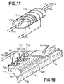
- FIG. 17 illustrates an exemplary embodiment of such a device.
- the sensor 2 of FIG. 15 is inserted into a tube 170, made of quartz for example.
- the assembly is surrounded by a resistive turn 173 supplied with the help of the connections 174 by an electric current.
- This current can be fixed once and for all to ensure an average temperature inside the tube or, on the contrary, be adjustable as a function of the temperature of the body of the sensor measured by a sensor 171, a thermocouple for example.
- the output signal from the thermocouple 171 is transmitted via the links 172 to a servo-control unit, not shown. Usually, this signal is compared with a reference value so as to adjust the current supplying the resistive heating coil 173 to a value compensating for the drifts in measured temperature.
- the device which has just been described adapts to the sensors produced according to all the variants previously described and can be implemented within the framework of the regulation system described in relation to FIGS. 15 and 16.
- the invention proposes a sensor structure making it possible to obviate this drawback.
- FIG. 18 A first embodiment of a sensor according to this approach is illustrated in FIG. 18 in partial view, in which cuts have been made to highlight the hidden parts of the sensor.
- several pumping cells are integrated into the sensor.
- these cells have a common electrolyte E 12 and a common electrode E4 which is the extension of the measurement electrode of the measurement cell in an identical manner to the structures previously described.
- the structure of the sensor in FIG. 18 is similar overall to that of the sensor described in relation to FIG. 5 and the constituent elements which are not necessary for understanding the present approach will no longer be described.
- Individual ion pumping cells are defined by the regions underlying the electrodes E 31 to E34, which are exposed on the surface of the insulator Si and on which electrical contacts have been established with the electrical connections C 31 to C 33 . More generally, the cells which are represented in FIG. 18 four in number can be of any number n.
- each of the electrodes can be traversed by an elementary current which can take the values, o, + ⁇ i or -Ai
- the equivalent control current i can take any discrete value between o and nAi, in absolute value.
- the amplitude of the shift of the tilting of the response curve of the measuring cell on either side of the stoichiometry of the gas mixture at the input of the sensor may take as many discrete values as the number of ion pumping cells with which the sensor is provided.
- the electrode E4 remains common to all the cells, but the solid electrolyte is divided into elementary tongues E 121 to E 124 deposited on the electrode E4 which is the extension of the measurement electrode E 2 / P 2 and protrude laterally , for example alternately on the two edges of the substrate S b . Electrodes E 31 to E 33 are deposited on the periphery and provide electrical contact with the connections C 3 , to C 34 .
- control of the ion pumping cells can be carried out in voltage or in current. In the latter case, it suffices to have a set of n elementary bipolar current sources, operating all or nothing under the control of signals delivered by the computer 6.
- the first is to regulate the operating temperature of the sensor. To do this, the device described in relation to FIG. 17 can be implemented.
- FIG. 20 schematically illustrates a circuit for controlling the voltage of the elementary ion pumping cells of a sensor produced according to the fourth approach, this in relation to the regulation system of FIG. 15.
- the computer 6 comprises a calculating member 60 developing a control word N for example in pure binary code transmitted to a decoding and interface circuit 61 which provides on the outputs S 1 to S 5 five control signals of binary type actuating each a switch, respectively 62 to 66.
- the switch 66 is intended to activate a positive + V c : 67 or negative -V c : 68 control voltage source, depending on the direction of the desired offset.
- the number of switches 62 to 65 closed determines the magnitude of the offset.
- These switches are each connected to one of the electrodes E 31 to E34 defining the elementary ion pumping cells.
- the common electrode E4 is connected to the link C 4 at the point common to the two sources 67 and 68.
- two ion pumping cells can be used to obtain the currents + Ai and - ⁇ i.
- each elementary cell must have a separate pair of electrodes: respectively To do this, the structures described in relation to FIGS. 11 to 14 will be used. If the electrodes E 41 and E 32 are connected to a potential + V c supplied by the control source, this by means of switches not shown, and the electrodes E 31 and E 42 at an OV potential, it follows that the two elementary cells can be crossed by currents -Ai and + Ai respectively, causing an offset of the tipping point of the response curve of the measuring cell not shown in FIG. 21, of the same amplitude but in the opposite direction. More generally the number of cells is equal to 2n
- this variant also adapts to the case where the two ion pumping cells are controlled analogically by a current or a voltage of variable amplitude, but of single polarity.
- the sensors produced according to the thin or thick film technique may be preferred for certain applications, since they have less inertia of response, less bulk and can be made according to the technology usually used in microelectronics. According to this last aspect, they can in particular be intimately associated with other electronic components produced on the same substrate or on a neighboring substrate, protected from high temperatures so that the electronic circuits can function properly.
- the connections C, / C 2 also produced by deposition, can be connected to a threshold amplifier intended to detect the tilting of the curves in FIG. 2. This aspect is outside the scope of the invention.
- Other advantages have been recalled in the aforementioned European patent applications.
Abstract
Description
L'invention se rapporte aux capteurs électrochimiques des concentrations d'espèces dans un mélange fluide et en particulier, à une système de régulation de la richesse d'un mélange gazeux air-carburant.The invention relates to electrochemical sensors for the concentrations of species in a fluid mixture and in particular to a system for regulating the richness of a gaseous air-fuel mixture.
Une des familles bien connues de capteurs électrochimiques fonctionne sur le principe de la pile à concentration et mesure la pression partielle, d'une ou plusieurs espèces du mélange gazeux à analyser. Ce mélange gazeux présent dans un premier compartiment, par exemple un mélange oxygènegaz inerte, est séparé d'un milieu de référence par la paroi d'un électrolyte solide dont chaque face porte une électrode. Comme il est bien connu, les équations qui régissent ces capteurs sont:
- -aux interfaces, électrodes/électrolyte:


- R=constante des gaz parfaits=8,314 (mole,°K)
- F=nombre de Faraday=96490C
- T=température absolue en degrés Kelvin
- P1 et P2=pressions partielles des
milieux 1 et 2 dans lescompartiments 1 et 2.
- -at interfaces, electrodes / electrolyte:
- R = ideal gas constant = 8.314 (mole, ° K)
- F = Faraday number = 96490C
- T = absolute temperature in degrees Kelvin
- P 1 and P 2 = partial pressures of
media compartments
Dans le cas où le mélange est réactif, par exemple un mélange 02+CO, et si l'électrode est un catalyseur de la réaction de ces gaz, il se produit la réaction:
![]()

![]()
Les approches récentes de réalisation de capteurs proposent l'utilisation d'un moyen combinant la fonction électrode et la fonction milieu de référence. On utilise pour ce faire une électrode à base d'une combinaison du type: M-MX où M est un métal et X de l'oxygène ou un halogène à détecter (par exemple M-MO dans le cas de la détection de l'oxygène). A titre de perfectionnement selon cette approche, il a été également proposé des capteurs réalisés selon la technique des couches minces utilisée en microélectronique. Ces deux types de réalisation permettent, entre autres, de s'affranchir en partie des effets parasites de la température sur la courbe de réponse des capteurs. En effet de par les équations (2) et (4), la valeur de VEijE2 dépend doublement du paramètre "température". Un choix convenable, d'après les tables de chaleur de formation du couple M-MX permet en effet de compenser en partie les deux termes sensibles à la température.Recent approaches for producing sensors propose the use of a means combining the electrode function and the reference medium function. To do this, an electrode based on a combination of the type is used: M-MX where M is a metal and X is oxygen or a halogen to be detected (for example M-MO in the case of detection of the oxygen). By way of improvement according to this approach, sensors have also been proposed produced according to the thin film technique used in microelectronics. These two types of embodiment allow, among other things, to overcome in part the parasitic effects of temperature on the response curve of the sensors. Indeed by equations (2) and (4), the value of V EijE2 depends doubly on the "temperature" parameter. A suitable choice, according to the heat formation tables for the M-MX couple, makes it possible to partially compensate for the two temperature-sensitive terms.
L'invention concerne des capteurs du type comprenant des électrodes-ou d'autres moyens placés en amont de la cellule électrochimique de mesure réalisant la catalyse complète, de telle sorte que le mélange gazeux à analyser atteigne l'équilibre thermodynamique au moins au niveau de l'interface électrode-électrolyte et dont l'une des électrodes est du type décrit ci-dessus à base d'une combinaison M-MX.The invention relates to sensors of the type comprising electrodes or other means placed upstream of the electrochemical measurement cell carrying out the complete catalysis, so that the gas mixture to be analyzed reaches thermodynamic equilibrium at least at the electrode-electrolyte interface and one of the electrodes of which is of the type described above based on an M-MX combination.
De tels capteurs sont utilisés couramment pour la régulation des moteurs à combustion interne et en particulier pour la régulation de l'admission du mélange air-carburant au niveau du carburateur ou de l'injecteur de carburant. Le capteur est alors placé dans le circuit d'échappement et analyse la concentration relative des espèces oxygène- oxyde de carbone, contenues dans le gaz. Le capteur doit alors être adapté à certaines caractéristiques spécifiques à cette utilisation. En effet le gaz d'échappement va arriver par saccades, au rythme du mouvement alternatif des différents pistons. On résoud ces difficultés en prélevant des échantillons de gaz à analyser, qui seuls sont admis à l'intérieur du capteur où ils seront amenés à l'équilibre thermodynamique. On parle de "prise d'essai" qui, si elles sont suffisamment rapprochées, tendent vers une analyse en continu, bien qu'en réalité le capteur fonctionne en régime dynamique. Pour arriver à ce résultat, on dispose habituellement en amont du capteur des moyens qui freinent sélectivement les gaz qui les traversent et qui limitent l'échange gazeux entre le milieu extérieur et l'intérieur du capteur. Par analogie aux lois qui régissent les circuits électriques, on peut appeler ces moyens: "impédance de transfert". Diverses solutions ont été proposées qui reposent sur deux approches: selon la première approche le mélange gazeux à analyser pénètre dans le capteur par un ou plusieurs orifices calibrés; selon la seconde approche le mélange gazeux traverse un matériau solide poreux, c'est en général le cas des capteurs de structure plane réalisés par les techniques des couches minces. Le matériau poreux peut également être confondu avec le prolongement de l'électrode de mesure. Dans une variante particulièrement avantageuse de capteur de l'art connu, l'électrode se présente sous la forme d'une couche de matériau catalyseur poreux et le gaz à analyser se propage en son sein selon une direction parallèle aux plus grandes dimensions de l'électrode avant d'atteindre la zone de mesure proprement dite. Un tel capteur est décrit dans les demandes de brevets Européens EP-A-00110 38 et EP-A-0-012647.Such sensors are commonly used for regulating internal combustion engines and in particular for regulating the admission of the air-fuel mixture to the carburetor or the fuel injector. The sensor is then placed in the exhaust circuit and analyzes the relative concentration of the oxygen-carbon monoxide species contained in the gas. The sensor must then be adapted to certain characteristics specific to this use. Indeed the exhaust gas will arrive in jerks, at the rate of the reciprocating movement of the different pistons. These difficulties are resolved by taking samples of the gas to be analyzed, which alone are admitted inside the sensor where they will be brought to thermodynamic equilibrium. We speak of "test sample" which, if they are close enough, tend towards a continuous analysis, although in reality the sensor operates in dynamic regime. To achieve this result, means are usually available upstream of the sensor which selectively brake the gases which pass through them and which limit the gas exchange between the external environment and the interior of the sensor. By analogy to the laws that govern electrical circuits, we can call these means: "transfer impedance". Various solutions have been proposed which are based on two approaches: according to the first approach, the gaseous mixture to be analyzed enters the sensor through one or more calibrated orifices; according to the second approach, the gas mixture passes through a porous solid material, this is generally the case of flat structure sensors produced by the techniques of thin layers. The porous material can also be confused with the extension of the measuring electrode. In a particularly advantageous variant of a sensor of the known art, the electrode is in the form of a layer of porous catalyst material and the gas to be analyzed propagates within it in a direction parallel to the largest dimensions of the electrode before reaching the actual measurement area. Such a sensor is described in European patent applications EP-A-00110 38 and EP-A-0-012647.
Les capteurs dont le 'fonctionnement et les principales caractéristiques viennent d'être rappelés ont des courbes de réponse qui présentent un basculement brusque lorsque la stoéchiométrie du mélange gazeux à analyser est atteinte. En outre, la réponse de ces capteurs ne se réduit pas à une courbe unique mais à un jeu de courbes, paramétrées en température du fait de la dépendance déjà indiquée et, qui se confondent sensiblement dans la région du basculement. On ne peut donc habituellement n'utiliser que cette partie des courbes de réponse et par là ne détecter de façon sûre et répétitive que la stoéchiométrie de la réaction définie par la relation (3).Sensors whose 'operation and the main features just mentioned have response curves which have a sudden shifting when the stoichiometry of the gas mixture to be analyzed is reached. In addition, the response of these sensors is not reduced to a single curve but to a set of curves, parameterized in temperature due to the dependence already indicated and, which substantially merge in the tilting region. One can therefore usually only use this part of the response curves and thereby only reliably and repetitively detect the stoichiometry of the reaction defined by equation (3).
Ces capteurs peuvent être utilisés tels quels dans certains pays, en particulier dans les pays imposant des normes anti-pollution sévères. Le moteur fonctionne alors avec un mélange air-carburant stoéchiométrique.These sensors can be used as they are in certain countries, in particular in countries imposing strict anti-pollution standards. The engine then operates with a stoichiometric air-fuel mixture.
Dans d'autres pays, tels que certains pays européens, d'autres contraintes, et notamment des mesures d'économie sur les carburants, imposent un mélange pauvre. Les capteurs de l'art connu, ayant une courbe de réponse "tout ou rien" pour un seul point de régulation, ne sont pas adaptés à ce type de fonctionnement.In other countries, such as certain European countries, other constraints, and notably fuel economy measures, impose a lean mixture. The sensors of the prior art, having an "all or nothing" response curve for a single regulation point, are not suitable for this type of operation.
Pour résoudre ce problème et plus généralement pour modifier le point de régulation, deux approches ont été proposées.To solve this problem and more generally to modify the regulation point, two approaches have been proposed.
Selon la première approche, en modifiant certains des éléments constitutifs de ces capteurs, notamment en adoptant une structure particulière d'électrodes de mesure, il est possible de linéariser la courbe de réponse en partie. De tels capteurs sont décrits dans la demande de brevet européen EP-A-0018871 publiée le 12 novembre 1980. Le dispositif décrit est sensible non plus à l'oxygène mais au monoxyde de carbone; ce qui présente un avantage car le dynamique de variation de la teneur en monoxyde de carbone est habituellement plus importante que celle en oxygène dans les gaz d'échappement. Cependant ce dispositif ne peut être utilisé que dans une gamme restreinte de concentrations relatives au delà de laquelle les effets parasites de la température deviennent trop importants pour assurer une précision de mesure suffisante.According to the first approach, by modifying some of the constituent elements of these sensors, in particular by adopting a particular structure of measurement electrodes, it is possible to linearize the response curve in part. Such sensors are described in European patent application EP-A-0018871 published on November 12, 1980. The device described is no longer sensitive to oxygen but to carbon monoxide; which has an advantage because the dynamic variation of the carbon monoxide content is usually greater than that of oxygen in the exhaust gas. However, this device can only be used in a limited range of relative concentrations beyond which the parasitic effects of temperature become too great to ensure sufficient measurement accuracy.
Selon la seconde approche, "l'impédance de transfert" telle que précédemment définie est rendue sélective par l'utilisation d'un matériau poreux spécialement adapté au fluide à analyser.According to the second approach, the "transfer impedance" as defined above is made selective by the use of a porous material specially adapted to the fluid to be analyzed.
En effet dans le cas d'un mélange gazeux de deux espèces, par exemple de l'oxygène et de l'oxyde de carbone, l'une des espèces peut diffuser plus rapidement que l'autre au sein du matériau poreux en question. En d'autres termes à une composition de mélange donnée à l'entrée du capteur, peut correspondre une composition de mélange différente au sein du matériau poreux et ensuite au niveau de l'électrode de mesure.Indeed, in the case of a gaseous mixture of two species, for example oxygen and carbon monoxide, one of the species can diffuse more quickly than the other within the porous material in question. In other words, a mixture composition given at the input of the sensor can correspond to a different mixture composition within the porous material and then at the level of the measurement electrode.
En intégrant dans le capteur une impédance de transfert sélective prédéterminée, associée à des moyens de catalyse destinés à amener le mélange gazeux en équilibre thermodynamique avant analyse, on mesure la concentration apparente des espèces d'un mélange gazeux, c'est à dire celle qui existe au niveau de l'électrode de mesure, et par là on décale le point de régulation de part ou d'autre de la stoechiométrie du mélange gazeux circulant réellement dans les conduits d'échappement.By integrating into the sensor a predetermined selective transfer impedance, associated with catalysis means intended to bring the gas mixture into thermodynamic equilibrium before analysis, the apparent concentration of the species of a gas mixture is measured, that is to say that which exists at the level of the measurement electrode, and by this the regulation point is shifted on either side of the stoichiometry of the gaseous mixture actually circulating in the exhaust ducts.
Un système de régulation utilisant ce type de capteur, décrit dans la demande de brevet européen EP-A-0011530 publiée le 20 mai 1980, est moins dépendant des effets de la température puisque dans ce cas on détecte également le basculement de la courbe de réponse, basculement qui se produit de part ou d'autre de la stoechiométrie en fonction de la nature 1"'impédance de transfert", c'est à dire dans une région de la courbe moins sensible à ce paramètre. Cependant l'amplitude du décalage permis par ces dispositifs est relativement limité et fixé une fois toute à une valeur prédéterminée au moment de la fabrication.A regulation system using this type of sensor, described in European patent application EP-A-0011530 published on May 20, 1980, is less dependent on the effects of temperature since in this case the tilting of the response curve is also detected. , tilting which occurs on either side of the stoichiometry according to the
Dans certaines applications, notamment dans les systèmes de régulation de la richesse du mélange air-carburant admis dans les cylindre d'un moteur à combustion interne pilotés par un calculateur numérique ou analogique, il est nécessaire de pouvoir faire évoluer le point de régulation en fonction de paramètres mesurés par différents capteurs tels que la température ou la vitesse du véhicule entrainé par le moteur, ce de façon continue selon des lois préétablies ou élaborées par le calculateur.In certain applications, in particular in systems for regulating the richness of the air-fuel mixture admitted into the cylinders of an internal combustion engine controlled by a digital or analog computer, it is necessary to be able to change the regulation point as a function parameters measured by different sensors such as the temperature or the speed of the vehicle driven by the engine, this continuously according to pre-established laws or developed by the computer.
Les capteur de l'art connu ne sont pas adaptés à ces types de fonctionnement, l'invention vise à combler ce besoin en se servant d'une structure de capteur intégrant un organe du type pompe ionique permettant de faire évoluer de façon continue la concentration relative apparente mesurée au niveau de l'électrode de mesure, ce a l'aide d'un courant électronique de commande.The sensors of the known art are not suitable for these types of operation, the invention aims to fill this need by using a sensor structure incorporating a member of the ion pump type making it possible to continuously change the concentration. apparent relative measured at the measurement electrode, using an electronic control current.
Ce type d'organe est utilisé dans l'art connu pour réguler la concentration d'une espèce chimique dans une enceinte ou une conduite, par exemple de l'oxygène, en effectuant un pompage réversible de cette espèce contenue dans une seconde enceinte réservoir.This type of organ is used in the known art to regulate the concentration of a chemical species in an enclosure or a pipe, for example oxygen, by carrying out a reversible pumping of this species contained in a second reservoir enclosure.
Une pompe ionique a généralement une structure analogue à celle d'une cellule électrochimique: une membrane constituée par un électrolyte solide perméable aux ions de l'espèce chimique à "pomper" comportant sur ses deux faces des électrodes reliées aux bornes d'une source de courant électronique. En fonction de l'amplitude et de la polarité du courant, il s'établit au sein de l'électrolyte un courant ionique se traduisant par le transport d'ions de l'espèce qui se recombinent sur une des deux électrodes selon le sens de conduction. Dans le cas de l'oxygène, la relation (1) précédement rappelée est satisfaite.An ion pump generally has a structure analogous to that of an electrochemical cell: a membrane constituted by a solid electrolyte permeable to ions of the chemical species to be "pumped" comprising on its two faces electrodes connected to the terminals of a source of electronic current. Depending on the amplitude and the polarity of the current, an ion current is established within the electrolyte resulting in the transport of ions of the species which recombine on one of the two electrodes according to the direction of conduction. In the case of oxygen, the relation (1) previously recalled is satisfied.
Une exemple de pompe ionique est décrit dans l'article de FOULETIER et autres: "Measurement and regulation of oxygen content in gases using solid electrolyte cells. III. Oxygen pump-gauge", paru dans la revue Britanique: "Journal of Applied Electrochemistry", n°5,1975, pages 111-120.An example of an ion pump is described in the article by FOULETIER et al: "Measurement and regulation of oxygen content in gases using solid electrolyte cells. III. Oxygen pump-gauge ", published in the British review:" Journal of Applied Electrochemistry ", n ° 5,1975, pages 111-120.
De telles pompes ioniques sont également utilisées dans des dispositifs de mesure de la quantité d'oxygène compris dans un échantillon d'un mélange gazeux admis dans une enceinte de mesure. La méthode mise en oeuvre consiste à séparer l'oxygène des autres espèces chimiques comprises dans le mélange. Pour ce faire, la pompe ionique pompe l'oxygène hors de l'enceinte au travers d'un électrolyte solide conducteur ionique de l'oxygène. La quantité d'oxygène présente dans le mélange gazeux peut être déterminée par le biais de la mesure de la quantité de charges électriques fournies à la pompe ionique pour extraire cet oxygène de l'enceinte.Such ion pumps are also used in devices for measuring the quantity of oxygen included in a sample of a gaseous mixture admitted into a measurement enclosure. The method used consists in separating the oxygen from the other chemical species included in the mixture. To do this, the ion pump pumps oxygen out of the enclosure through a solid ionic conductor of oxygen ion. The amount of oxygen present in the gas mixture can be determined by measuring the amount of electrical charge supplied to the ion pump to extract this oxygen from the enclosure.
Les dispositifs de mesure de ce type, décrits, par exemple, dans le brevet US-A-3 907 657, sont également munis d'une cellule électrochimique de mesure mesurant une faible concentration en oxygène dans l'enceinte de mesure. Cette mesure s'effectue en détectant une forte différence de potentiel aux bornes de la cellule de mesure d'amplitude déterminée.Measuring devices of this type, described, for example, in US-A-3,907,657, are also provided with an electrochemical measurement cell measuring a low oxygen concentration in the measurement enclosure. This measurement is carried out by detecting a large potential difference across the terminals of the measurement cell of determined amplitude.
Une variante de cette méthode est décrite dans la demande de brevet européen EP-A-0035400 publiée le 9 Septembre 1981. On alimente la pompe ionique avec un courant variable, d'amplitude telle que la différence de potentiel qui se développe aux bornes de la cellule de mesure reste constante, ce qui implique que la concentration en oxygène dans l'enceinte de mesure est également constante, des moyens étant prévus pour maintenir aussi constante le température du mélange gazeux. L'amplitude du courant électrique qui doit être fourni à la pompe ionique varie linéairement en fonction de la concentration en oxygène dans le mélange gazeux admis dans l'enceinte. De la connaissance de ce courant peut être déduite la mesure de la concentration en oxygène.A variant of this method is described in European patent application EP-A-0035400 published on September 9, 1981. The ion pump is supplied with a variable current, of amplitude such that the potential difference which develops across the terminals of the measurement cell remains constant, which implies that the oxygen concentration in the measurement enclosure is also constant, means being provided to keep the temperature of the gas mixture as constant. The amplitude of the electric current which must be supplied to the ion pump varies linearly as a function of the oxygen concentration in the gaseous mixture admitted into the enclosure. From the knowledge of this current can be deduced the measurement of the oxygen concentration.
L'invention a donc pour objet un capteur électrochimique tel que spécifié dans les revendications 1 ou 3.The subject of the invention is therefore an electrochemical sensor as specified in
L'invention a encore pour objet un système de régulation de la richesse du mélange air-carburant d'un moteur à combustion mettant en oeuvre un capteur tel que spécifié dans les revendications 1 à 11, ledit système étant défini dans la revendication 12.The subject of the invention is also a system for regulating the richness of the air-fuel mixture of a combustion engine using a sensor as specified in
L'invention sera mieux comprise et d'autres caractéristiques apparaîtront à la lecture de la description ci-après en se référant aux dessins annexés parmi lesquels:
- les figures 1
et 2 illustrent un exemple de capteur électrochimique de l'art connu et son fonctionnement. - la figure 3 illustre schématiquement une pompe ionique.
- La figure 4 est un diagramme illustrant le fonctionnement d'un capteur réalisé selon l'invention.
- la figure 5 est un premier exemple de réalisation d'un capteur conforme à l'invention selon une première approche.
- les figures 6 à 10 illustrent d'autres exemples de réalisation selon cette approche.
- les figures 11 à 13 illustrent des exemples de réalisation selon une deuxième approche.
- la figure 14 illustre un exemple de réalisation selon une troisième approche.
- les figures 15 et 16 illustrent un système de régulation dans lequel les capteurs de l'invention sont mis en oeuvre et, sont fonctionnement.
- la figure 17 illustre un perfectionnement pouvant être apporté aux capteurs de l'invention.
- les figures 18 et 19 illustrent deux exemples de réalisation de capteurs conformes à l'invention selon une quatrième approche.
- la figure 20 illustre schématiquement la mise en oeuvre d'un tel capteur dans un système de régulation.
- la figure 21 est une variante apportée à la mise en oeuvre d'un capteur réalisé selon la quatrième approche.
- Figures 1 and 2 illustrate an example of an electrochemical sensor of the known art and its operation.
- Figure 3 schematically illustrates an ion pump.
- FIG. 4 is a diagram illustrating the operation of a sensor produced according to the invention.
- Figure 5 is a first embodiment of a sensor according to the invention according to a first approach.
- Figures 6 to 10 illustrate other exemplary embodiments according to this approach.
- Figures 11 to 13 illustrate exemplary embodiments according to a second approach.
- FIG. 14 illustrates an exemplary embodiment according to a third approach.
- FIGS. 15 and 16 illustrate a regulation system in which the sensors of the invention are implemented and are functioning.
- FIG. 17 illustrates an improvement which can be made to the sensors of the invention.
- Figures 18 and 19 illustrate two exemplary embodiments of sensors according to the invention according to a fourth approach.
- FIG. 20 schematically illustrates the implementation of such a sensor in a regulation system.
- FIG. 21 is a variant brought to the implementation of a sensor produced according to the fourth approach.
La figure 1 décrit un exemple de structure de capteur de l'art connu, incorporant simultanément les fonctions de "prise d'essai", de catalyse et de mesure proprement dite et réalisé selon les techniques de dépôt en couche mince ou en couche épaisse. Dans ce qui suit on supposera que les capteurs électrochimiques décrits sont destinés à la détection des concentrations relatives d'oxygène et de monoxyde de carbone, sans que cela soit limitatif de la portée de l'invention. Les principales caractéristiques d'un tel capteur vont être rappelées dans ce qui suit à titre d'illustration de l'art connu.FIG. 1 describes an example of a sensor structure of the prior art, simultaneously incorporating the functions of "test portion", of catalysis and of measurement proper and produced according to the deposition techniques in thin layer or in thick layer. In what follows, it will be assumed that the electrochemical sensors described are intended for the detection of the relative concentrations of oxygen and carbon monoxide, without this being limiting the scope of the invention. The main characteristics of such a sensor will be recalled in the following by way of illustration of the known art.
Le capteur de la figure 1 comporte deux électrodes déposées sur un électrolyte solide E, lui-même déposé sur le substrat Sb. Les électrodes E1/P1 et E2 sont situées dans un même plan. L'électrode E1/P1 combine les fonctions d'électrode et de milieu de référence. L'électrode E1/Pj est en outre protégée du milieu extérieur par un isolant étanche et inerte S1, qui la recouvre. On peut utiliser une association du type Ni/Ni 0 pour réaliser cette électrode-milieu de référence. L'électrode E2 comporte deux zones et communique directement avec le milieu à analyser Mex dans lequel circule le mélange gazeux G par un orifice pratiqué dans le corps isolant S1 qui la recouvre également. Dans la première zone Ct, l'électrode est isolée en sa face inférieure de l'électrolyte El par un corps isolant S2 du même type que S1, sur une longueur 1c. Le fluide à analyser doit traverser le corps Ct qui est un catalyseur. Dans cette zone les espèces réactives du mélange à analyser (par exemple, dans le cas des gaz d'échappement: CO et 02) sont amenés à l'équilibre thermodynamique complet avant qu'elles n'atteignent la cellule électrochimique proprement dite:![]()
![]()
P2 constitue le milieu réel à analyser. Dans un exemple de réalisation pratique, la zone Ct n'est que le prolongement de l'électrode E2/P2 et est constituée par le même matériau, par exemple du platine, déposé en couche mince. La catalyse s'effectue par la traversée du catalyseur par le fluide suivant une direction parallèle au plan des électrodes. Les électrodes sont prolongées vers l'extérieur par des liaisons métalliques sur lesquelles peuvent être soudés les contacts Ci et C2, liaisons qui sont réalisées en laque de platine par exemple. Le substrat Sb peut être constitué par un bon isolant à la température de fonctionnement du dispositif (du corindon par exemple) et assure la tenue mécanique de l'ensemble. Ce substrat peut être prolongé selon une direction quelconque pour être adapté à des moyens de fixation à un boitier.P 2 constitutes the real medium to be analyzed. In a practical embodiment, the area C t is not that the extension of the electrode E 2 / P 2 and consists of the same material, for example platinum, deposited in a thin layer. The catalysis is carried out by the fluid passing through the catalyst in a direction parallel to the plane of the electrodes. The electrodes are extended towards the outside by metal connections on which the contacts Ci and C 2 can be welded, connections which are produced in platinum lacquer for example. The substrate S b can be constituted by a good insulator at the operating temperature of the device (corundum for example) and ensures the mechanical strength of the assembly. This substrate can be extended in any direction to be adapted to means for fixing to a housing.
Dans une variante non illustrée, l'électrolyte solide peut être constitué d'une plaque épaisse et le substrat ne pas exister.In a variant not illustrated, the solid electrolyte can consist of a thick plate and the substrate does not exist.
Des valeurs typiques sont:
- -longeur |c: 0,1 mm à 0,5 mm
- -épaisseur des électrodes: 1000 À à 100 pm
- -épaisseur de l'électrolyte: 1000 À à 100 µm
- -length | c : 0.1 mm to 0.5 mm
- - thickness of the electrodes: 1000 to 100 pm
- - electrolyte thickness: 1000 to 100 µm
Les dépôts peuvent être réalisés par les techniques bien connues, telles que: dépôt sous vide (pulvérisation cathodique, évaporation), dépôt en phase vapeur, dépôt électrochimique ou implantation ionique ou par une combinaison de deux ou plusieurs de ces techniques.Deposits can be carried out by well-known techniques, such as: vacuum deposition (sputtering, evaporation), vapor deposition, electrochemical deposition or ion implantation or by a combination of two or more of these techniques.
La figure 2 illustre un jeu de courbes de réponse des capteurs de concentration de l'oxygène de l'art connu dans les gaz d'échappement d'un moteur à combustion interne. Chaque courbe représente la différence de potentiel inter- électrode VE1/E2 en fonction de la concentration de l'oxygène dans les gaz d'échappement, à température constante. Il est à remarquer trois zones: dans les zones 1 et III, les différentes courbes sont nettement différenciées les unes des autres. En effet, si on se reporte aux relations (2) et (4) rappelées précédemment, on remarque que ces relations contiennent toutes deux le paramètre "température absolue T". Il est dont difficile d'exploiter ces parties de courbes, car les gaz d'échappement n'ont pas une température constante. Par contre dans la zone Il de la figure 2, qui correspond au basculement, les différentes courbes sont pratiquement confondues. Aussi seule cette zone est habituellement exploitée. La sortie du capteur est transmise à une organe de commande électrique (non représenté) qui détecte le basculement rapid de la courbe VE1/E2 autour du point d'abscisse λs, qui représente le rapport stoechiométrique du mélange, tel qu'il est mesuré au niveau de l'électrode de mesure E2/P1. Le point de basculement est fixé, même si l'on peut par le procédé décrit dans la demande de brevet européen EP-A-0011530 précitée décaler légèrement au moment de la fabrication du capteur ce point de basculement de part ou d'autre de la stoechiométrie.FIG. 2 illustrates a set of response curves of the oxygen concentration sensors of the prior art in the exhaust gases of an internal combustion engine. Each curve represents the difference in inter-electrode potential V E1 / E2 as a function of the concentration of oxygen in the exhaust gases, at constant temperature. Three zones should be noted: in
L'invention vise à s'affranchir de cette limitation. Pour ce faire la structure du capteur intègre une cellule supplémentaire analogue à la cellule de mesure E1-E1-E2 fontionnant en pompe ionique, et qui sera appelée dans ce qui suit cellule de pompage ionique.The invention aims to overcome this limitation. To do this, the structure of the sensor incorporates an additional cell analogous to the measurement cell E 1 -E 1 -E 2 operating as an ion pump, and which will be called in the following ion pumping cell.
Une tell pompe ionique est décrite schématiquement par la figure 3. Elle se présente substantiellement sous la forme d'une cellule électrochimique comprenant un électrolyte solide E,' conducteur ionique d'au moins une espèce chimique déterminée, par exemple de l'oxygène, de forme annulaire dan l'exemple choisi sur les faces interne et externe duquel a été déposée une paire d'électrodes, respectivement E1' et E2'. Si on applique une différence de potentiel Vc entre les électrodes, selon l'amplitude et la polarité, il se crée un courant ionique au sein de l'électrolyte, c'est à dire d'un transport d'ions de l'espèce considérée de l'électrode E2' à l'électrode E1' ou inversement, l'amplitude de ce courant ionique étant reliée par une loi déterminée à l'amplitude de la tension de commande Vc. Les électrodes doivent être poreuses ou perméables à l'espèce chimique déterminée. On considèrera dans ce qui suit, l'exemple de l'oxygène, étant entendu que l'oxygène peut être pur ou être compris dans un mélange de divers fluides. Le courant ionique au sein de l'electrolyte se traduit par un courant électronique i dans le circuit électrique extérieur à la cellule. Le courant i peut de déduire de la relation (1) précitée.A tell ion pump is described schematically in Figure 3. It is substantially in the form of an electrochemical cell comprising a solid electrolyte E, the ion conductor of at least one specific chemical species, for example oxygen, annular shape in the example chosen on the inner and outer faces of which has been deposited a pair of electrodes, E 1 'and E 2 ' respectively. If a potential difference V c is applied between the electrodes, depending on the amplitude and the polarity, an ion current is created within the electrolyte, that is to say a transport of ions of the species considered from the electrode E 2 'to the electrode E 1 ' or vice versa, the amplitude of this ion current being linked by a determined law to the amplitude of the control voltage V c . The electrodes must be porous or permeable to the determined chemical species. The example of oxygen will be considered in what follows, it being understood that the oxygen can be pure or be included in a mixture of various fluids. The ion current within the electrolyte results in an electronic current i in the electrical circuit outside the cell. The current i can deduce from the above relation (1).
Les lois régissant le fonctionnement de telles cellules de pompage ionique sont connues de l'homme de métier. Il peut être utile cependant de rappeler les relations suivantes simplifiées, s'il est supposé que la conductivité électronique propre de l'électrolyte est négligeable.The laws governing the operation of such ion pumping cells are known to those skilled in the art. It may be useful, however, to recall the following simplified relationships, if it is assumed that the proper electronic conductivity of the electrolyte is negligible.
Tout d'abord la cellule développe une force contre-électromotrice propre VE1/E2 donnée par la loi de NERNST et explicitée par le relation (2).First of all, the cell develops an own counter-electromotive force V E1 / E2 given by the law of NERNST and explained by the relation (2).
La masse totale en gramme de l'espèce transportée sous forme d'ions est donnée par la relation:
- i est le courant électronique
- t le temps en seconde
- M la mass atomique de l'espèce considérée et Z sa valence
- i is the electronic current
- t the time in seconds
- M the atomic mass of the species considered and Z its valence
Pour l'oxygène, la relation devient:
Le courant i peut être établi à partie de la relation:
En combinant (5) et (1) én obtient:
Dans l'exemple décrit en relation avec la figure 3, P1 at P2 sont les pressions partielles respectivement des milieux 1 et Il, le milieu Il peut être considéré comme un milieu réservoir contenant au moins de l'oxygène et le milieu I le milieu dans lequel circule un mélange gazeux dont la concentration en oxygène doit être régulée. Dans le cadre de l'exemple choisi un mélange gazeux G circule dans une conduite, traverse l'enceinte 1 constituée par l'intérieur de la pompe ionique et ressort sous forme d'un mélange gazeux G' avec une concentration en oxygène modifiée par la pompe ionique. De façon habituelle on place en sortie un capteur de mesure électrochimique S, mesurant la concentration du mélange en sortie G'. Les signaux électriques sont transmis à un comparateur Co qui reçoit sur une seconde entrée une valeur de consigne Ref de façon à agir sur la tension de commande Vo et par le fait même sur le courant i, en amplitude et en polatiré.In the example described in relation to FIG. 3, P 1 and P 2 are the partial pressures of
Le flux d'oxygène "pompé" obéit à la loi de FARADAY et est donné par la relation:
Comme il a été rappelé, l'invention propose un capteur comprenant deux cellules électrochimiques. La première cellule détectant la stoéchiométrie d'un faible volume de mélange gazeux qui lui est transmis après catalyse, ce faible volume de mélange gazeux provenant d'une "prise d'essai". La seconde cellule est une pompe ionique et modifie la composition du mélange gazeux admis à l'intérieur du capteur de manière à ce que le signal de sortie VE1/E2 de la cellule de mesure présente un basculement pour une valeur différente de la stoechiométrie du mélange gazeux telle qu'il se présente réellement à l'entrée du capteur (Mex).As has been recalled, the invention proposes a sensor comprising two electrochemical cells. The first cell detecting the stoichiometry of a small volume of gas mixture which is transmitted to it after catalysis, this small volume of gas mixture coming from a "test sample". The second cell is an ion pump and modifies the composition of the gas mixture admitted inside the sensor so that the output signal V E1 / E2 of the measurement cell has a tilting for a value different from the stoichiometry of the gas mixture as it actually appears at the sensor inlet (Mex).
la figure 4, illustre schématiquement le fonctionnement d'un capteur selon l'invention. On retrouve sous la référenc 40, les trois fonctions communes aux capteurs de l'art connu, par exemple le capteur décrit en relation avec la figure 1: "prise d'essais" 41, "catalyse" 42 et "cellule de mesure" 43, ces fonctions pouvant être tout ou en partie rèalisées par un organe commun. La composition du mélange gazeux G' après prise d'essai, dans l'art connu, étant identique ou très proche de la composition du mélange gazeux dans le milieu extérieur Mex où circule le mélange à mesurer. Avant mesure, le mélange gazeux G" vérifie la relation (4). La cellule de pompage ionique 44, à l'aide d'une tension de commande Vc, permet de modifier en continu la composition du mélange gazeux admis G' en injectant ou retirant de l'oxygène. Comme il est connu la fonction "prise d'essai" peut être réalisée de différentes manières: à l'aide d'un orifice calibré, d'un corps poreux inerte ou encore, dans le cas des capteurs analogues à celui de la figure 1, à l'aide du corps catalyseur lui-même Ci prolongeant l'électrode de mesure E2. Dans la réalité ces fonctions correspondent à des régions du capteur qui ne peuvent en général, être distinguées de façon aussi nette, un seul organe pouvant assurer à lui seul tout ou partie de ces fonctions. Le pompage ionique peut s'effectuer à tout endroit compris entre la cellule de mesure et la zone de prise d'essai, c'est à dire le plus souvent dans la zone de catalyse.Figure 4 schematically illustrates the operation of a sensor according to the invention. Found under the
Cette dernière structure est particulièrement intéressante car, elle permet simultanément une bonne sensibilité de mesure et une faible quantité de gaz admis: de l'ordre du mm3/s par exemple entre 0,5 et 5 mm3/s; ce outre les avantages d'ordre technologiques dus à l'utilisation des techniques de réalisation en couche minces ou épaisses. Il est dont possible de modifier notablement la composition en oxygène du mélange admis G' à l'intérieur du capteur sans nécessiter un courant ionique important au sein de l'électrolyte solide de la cellule de pompage ionique, c'est à dire de la tension de commande Vo ou ce qui revient au même du courant i.This latter structure is particularly advantageous since it simultaneously allows good measurement sensitivity and a small quantity of gas admitted: of the order of mm 3 / s for example between 0.5 and 5 mm 3 / s; this in addition to the technological advantages due to the use of production techniques in thin or thick layers. It is therefore possible to significantly modify the oxygen composition of the admitted mixture G 'inside the sensor without requiring a large ion current within the solid electrolyte of the ion pumping cell, that is to say of the voltage of control V o or what amounts to the same of current i.
Il est d'ailleurs plus intéressant d'utiliser une source de courant pour produire le courant de commande i. En effet si la cellule est commandée par une tension, le courant qui va la traverser est dépendant de la température comme il ressort clairement de la relation (6). Comme d'autre part la quantité d'ions transportée est directement proportionnelle au courant, il importe donc que ce soit le courant qui soit imposé et non la différence de potentiel si la température est susceptible de varier ou si des mesures de régulation de la température no sont pas mises en oeuvre. Dans ce qui suit on considèrera, sauf mention contraire que la source d'énergie électrique commandant la cellule de pompage ionique est une source de courant.It is moreover more advantageous to use a current source to produce the control current i. Indeed if the cell is controlled by a voltage, the current which will cross it is dependent on the temperature as it is clear from the relation (6). As, on the other hand, the quantity of ions transported is directly proportional to the current, it is therefore important that it is the current which is imposed and not the potential difference if the temperature is likely to vary or if temperature regulation measures no are not implemented. In what follows, it will be assumed, unless otherwise stated, that the source of electrical energy controlling the ion pumping cell is a current source.
La figure 5 illustre en coupe une première variante de réalisation de capteurs conformes à l'invention, selon une première approche.FIG. 5 illustrates in section a first alternative embodiment of sensors according to the invention, according to a first approach.
On retrouve les éléments communs à l'art connu, qui-a été illustré en relation avec la figure 1: la cellule de mesure![]()
![]()
Selon une caractéristique de. l'invention, une cellule électrochimique supplémentaire est intégrée dans le capteur et comprend un électrolyte solide E12 inséré entre deux électrodes E3 et E4. Dans l'exemple de réalisation de la figure 5 et selon la première approche, la seconde électrode E4 est confondue avec le prolongement de l'électrode de mesure E2. L'ensemble remplissant un canal percé dans l'enveloppe isolante. La cellule affleure en surface de l'isolant S1 de façon à communiquer avec un milieu contenant de l'oxygène, ce milieu pouvant être le milieu Mex dans lequel circule le mélange gazeux à analyser G. La cellule E3 E12-E4 est alimentée par un courant de commande i par l'intermédiaire des connexions C3 et C4, C4 étant confondu avec C2.According to a characteristic of. the invention, an additional electrochemical cell is integrated in the sensor and comprises a solid electrolyte E 12 inserted between two electrodes E 3 and E4. In the embodiment of FIG. 5 and according to the first approach, the second electrode E4 is merged with the extension of the measurement electrode E 2 . The assembly filling a channel pierced in the insulating envelope. The cell is exposed on the surface of the insulator S 1 so as to communicate with an oxygen-containing medium, this medium possibly being the Mex medium in which the gas mixture to be analyzed circulates G. The cell E 3 E 12 -E 4 is supplied by a control current i via the connections C 3 and C 4 , C 4 being merged with C 2 .
Si on se reporte à nouveau à la description qui précède en relation avec la figure 4, on voit immédiatement que la cellule E3-E12-E4 fonctionnant en pompbnionique modifie en fonction de l'amplitude et de la polarité du courant i, la composition de la prise d'essai admise dans le capteur, c'est à dire la composition du mélange gazeux circulant vers la zone de catalyse CI pour atteindre ultérieurement la cellule de mesure![]()
![]()
Les figures 6 à 10 représentent d'autres variantes de structures ou de procédés de réalisation de capteurs conformes à l'invention selon cette première approche. La figure 6 représente un mode de réalisation pratique dans lequel l'électrolyte E12 se présente sous la forme d'une couche ou d'une plaquette rapportée ou déposée sur le prolongement de l'électrode de mesure. Ensuite la couch d'émail est déposée. L'orifice découvrant l'électrolyte E,2 peut être réalisé par masquage et l'électrode E3 est ensuite déposée. Cette électrode peut être réalisée à l'aide d'une laque de platine.Figures 6 to 10 show other variants of structures or methods of producing sensors according to the invention according to this first approach. FIG. 6 represents a practical embodiment in which the electrolyte E 12 is in the form of a layer or a plate attached or deposited on the extension of the measurement electrode. Then the enamel coating is deposited. The opening revealing the electrolyte E, 2 can be produced by masking and the electrode E 3 is then deposited. This electrode can be produced using a platinum lacquer.
Les éléments communs avec ceux de la figure 5 ne seront plus décrits. Il en sera de même pour les figures qui vont être maintenant décrites.The elements common with those of FIG. 5 will no longer be described. It will be the same for the figures which will now be described.
L'électrolyte peut être sans inconvénient disposé à l'extrémité du substrat près de la zone de prise d'essai Pes comme illustré par la figure 7. Cette disposition évite de prévoir un orifice dans la couche d'émail S,.The electrolyte can easily be placed at the end of the substrate near the test sample area P es as illustrated in FIG. 7. This arrangement avoids providing an orifice in the enamel layer S,.
L'électrolyte peut également être disposé sous forme d'une couche sérigraphiée comme illustré par la figure 8.The electrolyte can also be arranged in the form of a screen-printed layer as illustrated in FIG. 8.
Enfin, il est encore possible de confondre les zones de prise d'essai et de pompage ionique, comme illustré par les figures 9 et 10, en rendant perméable l'électrode E3 au mélange gazeux G; la couche d'électrolyte solide E12 doit également être de faible épaisseur et perméable. La figure 10 illustre plus spécifiquement le cas où l'électrolyte est déposé par sérigraphie comme dans le cas de la figure 8.Finally, it is also possible to confuse the test sample and ion pumping zones, as illustrated by FIGS. 9 and 10, by making the electrode E 3 permeable to the gas mixture G; the solid electrolyte layer E 12 must also be thin and permeable. FIG. 10 more specifically illustrates the case where the electrolyte is deposited by screen printing as in the case of FIG. 8.
Dans ce qui vient d'être décrit l'électrode e4 était confondue avec le prolongement de l'électrode de mesure. Selon une seconde approche dont trois variantes sont illustrées en relation avec les figureu 11 à 13, l'électrode E4 peut être distincte et le cellule de pompage ionique E2-E12-E4 se présenter comme un élément rapporté sur l'émail protecteur S1.In what has just been described, the electrode e4 was merged with the extension of the measurement electrode. According to a second approach, three variants of which are illustrated in relation to the figures 11 to 13, the electrode E4 can be separate and the ion pumping cell E 2 -E 12 -E 4 appear as an element attached to the protective enamel. S 1 .
Selon la première variante, représentée par la figure 11, la zone "prise d'essai" Pas se présente sous la forme d'un orifice calibré, analogue à ceux mis en oeuvre dans certains types de capteurs de l'art connu, limitant de façon prédéterminée la quantité de mélange gazeux admis à l'intérieur du capteur, d'est à dire dans une enceinte sous- jacente à la cellule de pompage ionique dans laquelle la composition du mélange gazeux est modifiée et devient G', ce du à l'action de cette cellule. Cette enceinte peut être réalisée au moment de la fabrication par masquage et dépôt de la couche d'émail ou par tout autre procédé. Le cellule E3-E12-E4 est ensuite rapportée sur l'ensemble.According to the first variant, represented by FIG. 11, the "test portion" area Pas is in the form of a calibrated orifice, similar to those used in certain types of sensors of the known art, limiting predetermined amount of gas mixture admitted to the interior of the sensor, that is to say in an enclosure underlying the ion pumping cell in which the composition of the gas mixture is modified and becomes G ′, this due to the action of this cell. This enclosure can be produced at the time of manufacture by masking and depositing the enamel layer or by any other process. The cell E 3 -E 12 -E 4 is then added to the assembly.
Sur la figure 12, la cellule E3-E12-E14 est confondue également avec la zone de prise d'essai Pes, de façon analogue aux variantes des figures 9 et 10, de la première approche.In FIG. 12, the cell E 3 -E 12 -E 14 is also confused with the test sample area P es , in a manner analogous to the variants of FIGS. 9 and 10, of the first approach.
Sur la figure 13, la zone de prise d'essai Pas est distincte de la cellule E3-E12-E4 et réalisée de façon analogue aux variantes illustrées par les figures 5 à 8.In FIG. 13, the test portion Pas is distinct from the cell E 3 -E 12 -E 4 and produced in a manner analogous to the variants illustrated by FIGS. 5 to 8.
Selon une troisième approche, illustrée par la figure 14, en vue de dessus, la cellule de pompage ionique E3-E12-E4 peut être réalisée de façon analoque à celle de la cellule de mesure et présenter une structure globalement plane au lieu de se présenter sous la forme d'un empilement vertical:"électrode-électrolyte-électrode".According to a third approach, illustrated by FIG. 14, in top view, the ion pumping cell E 3 -E 12 -E 4 can be produced in a manner analogous to that of the measurement cell and have a generally planar structure instead to be in the form of a vertical stack: "electrode-electrolyte-electrode".
L'étrolyte E12 se prolonge vers l'extérieur en ressortant de la couche d'émail de protection S1. L'électrode E3 définit une zone utile d'échange avec l'oxygène présent dans le milieu extérieur et sert de prise de contact C3.The etolyte E 12 is extended towards the outside by coming out of the protective enamel layer S 1 . The electrode E 3 defines a useful zone for exchange with the oxygen present in the external medium and serves as contact point C 3 .
Une cellule réalisée selon cette structure peut également être adaptée à la seconde approche. On dépose alors une seconde électrode sur l'électrolyte, l'ensemble est déposé ou rapporté sur l'enveloppe isolante, la seconde électrode étant disposée sur le canal de communication avec la zone de catalyse de la cellule de mesure.A cell produced according to this structure can also be adapted to the second approach. A second electrode is then deposited on the electrolyte, the assembly is deposited or attached to the insulating envelope, the second electrode being disposed on the communication channel with the catalysis zone of the measurement cell.
Une des applications particulièrement intéressante des capteurs électrochimiques est leur mise en oeuvre dans les système de régulation de la richesse d'un mélange air-carburant admis dans un moteur à combustion interne: Dans l'art connu, ces capteurs sont insérés dans les conduits d'echappement et sont utilisés pour détecter la stoéchiométrie ou une valeur fixe qui en est proche, dans ces conduits, c'est à dire des gaz d'échappement. Des circuits électroniques à seuil détectent le basculement de la courbe à Às (figure 2) et des circuits de retroaction agissent sur des organes d'admission du mélange ai- carburant pour réaliser ces conditions. L'inconvénient de ces systèmes de régulation est de ne pouvoir définir qu'un seul point de régulation.One of the particularly interesting applications health of electrochemical sensors is their implementation in the regulation system of the richness of an air-fuel mixture admitted in an internal combustion engine: In the known art, these sensors are inserted in the exhaust ducts and are used to detect stoichiometry or a fixed value which is close to it, in these conduits, ie exhaust gases. Threshold electronic circuits detect the tilting of the curve at À s (Figure 2) and feedback circuits act on the fuel mixture intake members to achieve these conditions. The disadvantage of these regulation systems is that they can only define one regulation point.
Les capteurs conformes à l'invention permettant de décaler le basculement de la courbe de réponse en "avance" ou en "retard" par rapport à la stoéchiométrie réelle du mélange gazeux circulant dans les conduits d'échappement, ce de façon continue, sont particulièrement intéressant dans le cadre de cette application.The sensors according to the invention making it possible to offset the tilting of the response curve in "advance" or "delay" compared to the actual stoichiometry of the gaseous mixture circulating in the exhaust ducts, this continuously, are particularly interesting in the context of this application.
Les figures 15 et 16 illustrent schématiquement la mise en oeuvre de capteurs de l'invention dans un système de régulation de la richesse d'un mélange air-carburant admis dans les cylindres d'un moteur à combustion. Le moteur 1 comporte une admission d'air A et de carburant E qui sont mélangés dans un organe mélangeur 5. Celui-ci peut être un carburateur à cuve, un dispositif d'injection ou tout autre dispositif analogue. Le mélange est amené au moteur 1 par le conduit A/E. L'organe 5 est sous le contrôle d'un organe régulateur 4. La liaison 12 est par exemple un axe d'accouplement mécanique. Les gaz brûlés sont ensuite éjectés dans l'atmosphère AAb par un tuyau d'échappement Eo. Sur le trajet d'éjection des gaz est disposé un capteur 2 conforme à l'invention qui communique avec les gaz d'échappement G. En réalité le capteur, comme illustré sur la figure 15 est contenu dans un boîtier inséré dans le tuyau d'échappement et maintenu par toutes fixations appropriées. Ce boîtier offre une protection contre les agressions directes des gaz d'échappement. Seul un échantillon des gaz d'échappement ou "prise d'essai" est admis à l'intérieur du capteur 2 comme cela a été précédemment rappelé. Le signal électrique de sortie de la cellule de mesure Vs est transmis à une dispositif de commande 3 par les liaisons électriques 10. Le dispositif de commande doit être capable de détecter, par exemple à l'aide d'une logique à seuil, le basculement de la courbe VE1/E2 et sa sortie commande l'organe de régulation 4 par la liaison 11.Figures 15 and 16 schematically illustrate the implementation of sensors of the invention in a system for regulating the richness of an air-fuel mixture admitted into the cylinders of a combustion engine. The
L'architecture générale de ce système de régulation est similaire à celles des systèmes de l'Art Connu, notamment à celles décrites en relation avec les figures 14 et 15 du brevet EP-B-0 011 530.The general architecture of this regulation system is similar to that of known art systems, in particular to those described in relation to FIGS. 14 and 15 of patent EP-B-0 011 530.
A la figure 14 de ce brevet est représenté un système comportant un seul capteur détectant une valeur prédéterminée de la composition des gaz d'échappement, valeur fixée au moment de la fabrication.In Figure 14 of this patent is shown a system comprising a single sensor detecting a predetermined value of the composition of the exhaust gas, value set at the time of manufacture.
A la figure 15 de ce brevet est représenté un système comportant deux capteurs; nombre d'ailleurs qui peut être augmenté. Chaque capteur détecte une valeur distincte de la composition des gaz d'echappement, valeurs également fixée au moment de la fabrication.In Figure 15 of this patent is shown a system comprising two sensors; number which can be increased. Each sensor detects a distinct value of the composition of the exhaust gases, values also fixed at the time of manufacture.
Il est nécessaire pour bénéficier des avantages spécifiques des capteurs conformes à l'invention d'adjoindre à cette architecture de base, commune avec l'art connu, des moyens de génération du courant de commande de la pompe ionique intégrée dans la structure du capteur.To benefit from the specific advantages of the sensors according to the invention, it is necessary to add to this basic architecture, common with the prior art, means for generating the control current of the ion pump integrated in the structure of the sensor.
Si on désire réaliser une régulation automatique, le système de régulation est complété par un calculateur 6, analogique ou digital, qui reçoit de différents capteurs 7 ou d'organes de commande 7, par les liaisons 14, des informations sur des paramètres caractéristiques du fonctionnement du moteur, de l'environnement ainsi que des instructions diverses. Ces paramètres peuvent être, à titre d'exemple non limitatif la température extérieure, le débit d'air ou le régime du moteur: accéléré, ralenti, etc... Outre d'autres fonctions bien connue de l'homme de métier, telles que l'élaboration des impulsions électriques transmises aux bougies, et qui sortent du cadre de l'invention, le calculateur 6, génére à l'aide d'organes spécialisés le courant i servant à la commande de la cellule de pompage ionique dont est muni le capteur de l'invention 2, courant transmis par les liaisons électriques 13.If it is desired to carry out automatic regulation, the regulation system is supplemented by a
L'amplitude et la polarité du courant i servent à déterminer la quantité d'oxygène pompé, injecté ou extrait, pour modifier la composition de la prise d'essai et par là décaler le basculement de la courbe de réponse du capteur par rapport à la stoechiométrie du mélange gazeux circulant dans les conduits d'échappement Ec. Par l'effet de la rétroaction dûe aux organes 3 à 5, le mélange air-carburant admis dans le conduit A/E en est modifié en conséquence.The amplitude and polarity of the current i are used to determine the quantity of oxygen pumped, injected or extracted, to modify the composition of the test sample and thereby offset the tilting of the response curve of the sensor relative to the stoichiometry of the gas mixture circulating in the exhaust ducts E c . By the effect of the feedback due to the members 3 to 5, the air-fuel mixture admitted into the A / E line is modified accordingly.
La figure 16 illustre trois cas de fonctionnement du système de régulation de la figure 15, ce pour une température des gaz d'échappement donnée.FIG. 16 illustrates three cases of operation of the regulation system of FIG. 15, this for a given temperature of the exhaust gases.
Si i=0, tout se passe comme si la cellule de pompage ionique n'existait pas. La composition du mélange gazeux admis dans le capteur n'est pas modifiée par rapport a celle du milieu à analyser. Ce cas est illustré par le courbe C et c'est le cas des capteurs de l'art connu, le basculement se produit à la stoechiométrie du mélange circulant dans les conduites d'échappement. Ce cas est défini comme correspondant à une richesse R du mélange admis dans la conduite A/E, R=1. Un mélange pauvre est défini comme ayant in excès d'air et un mélange riche comme ayant un excès de carburant.If i = 0, everything happens as if the ion pumping cell did not exist. The composition of the gaseous mixture admitted into the sensor is not modified compared to that of the medium to be analyzed. This case is illustrated by curve C and this is the case with sensors of the prior art, the tilting occurs at the stoichiometry of the mixture circulating in the exhaust pipes. This case is defined as corresponding to a richness R of the mixture admitted in the line A / E, R = 1. A lean mixture is defined as having excess air and a rich mixture as having excess fuel.
Les courbes A et B correspondant à deux valeurs du courant de commande i, respectivement i1 et i2 telle que la relation![]()
![]()
Les points de basculement R" (mélange pauvre) et RB (mélange riche) correspondent à des décalages de même amplitude mais de sens contraires par rapport à la stoechiométrie. De la connaissance du courant de commande i, il peut être déterminé lorsqu'on détecte le basculement de la courbe la richesse du mélange air-carburant admis dans les cylindres du moteur. Il faut rappeler que ce basculement correspond à la stoechiométrie du mélange admis dans le capteur au niveau de l'électrode de mesure.The tipping points R " (lean mixture) and R B (rich mixture) correspond to shifts of the same amplitude but in opposite directions with respect to the stoichiometry. From the knowledge of the control current i, it can be determined when detects the tilting of the curve the richness of the air-fuel mixture admitted into the engine cylinders It should be remembered that this tilting corresponds to the stoichiometry of the mixture admitted into the sensor at the level of the measurement electrode.
En effet, la relation entre le courant de commande i et l'amplitude du décalage du basculement de la courbe par rapport à la stoechiométrie vraie du mélange gazeux à l'entrée du capteur, peut être déterminée par l'expérience ou par le calcul, à l'aide notamment des relations (6) et (7), connaissant la quantité de fluid admis dans le capteur par unité de temps ("prise d'essai"). Dans le cadre des structures de capteurs proches de celles du capteur décrit en relation avec la figure 5, comme il a été rappelé une valeur typique est de l'ordre du mm3/s.Indeed, the relation between the control current i and the amplitude of the shift of the tilting of the curve compared to the true stoichiometry of the gas mixture at the input of the sensor, can be determined by experience or by calculation, using in particular relations (6) and (7), knowing the quantity of fluid admitted into the sensor per unit of time ("test sample"). In the context of sensor structures close to those of the sensor described in relation to FIG. 5, as has been recalled, a typical value is of the order of mm 3 / s.
La richesse du mélange air-carburant admis dans les cylindres peut dont être régulée autour d'une valeur de consigne réglable de façon continue en agissant sur l'amplitude et la polarité du courant de commande i qui a son tour détermine la quantité d'oxygène "pompée". Pour ce faire le calculateur 6 incorpore une source de courant réglable ou programmable en amplitude et polarité (non représentée sur la figure 15). De telles sources réglables sont connues de l'homme de métier et ne nécessitent pas une plus ample description. Il en est de même des conditions exactes d'élaboration du courant i et des courbe de variation de la richesse du mélange admis en résultant. Ces courbes dépendent notamment du type de moteur utilisé.The richness of the air-fuel mixture admitted into the cylinders can therefore be regulated around a continuously adjustable setpoint by acting on the amplitude and the polarity of the control current i which in turn determines the quantity of oxygen. "pumped". To do this, the
D'autre part, cette méthode n'est pas limitée la régulation du mélange air-carburant d'un moteur à combustion interne. Sans rien changer à la structure du schéma de la figure 11, le moteur 1 peut être remplacé, à titre d'exemple non limitatif, par les brûleurs d'une chaudière. Le capteur 2 est alors placé dans le circuit Ec d'évacuation des gaz brûlés. Il peut être appliqué à tout appareil à effet de combustion, la régulation pour sa part peut être effectuée de façon non automatique en modifiant le courant i à l'aide d'un organe de commande manuelle de la source de courant.On the other hand, this method is not limited to regulating the air-fuel mixture of an internal combustion engine. Without changing anything in the structure of the diagram in FIG. 11, the
Une disposition supplémentaire pouvant être adoptée, pour assurer un meilleur fonctionnement du capteur de l'invention consiste à réguler la température de ce capteur à une valeur prédéterminée.An additional provision which can be adopted, to ensure a better functioning of the sensor of the invention consists in regulating the temperature of this sensor to a predetermined value.
Cette disposition peut être adoptée plusieurs raisons. En premier lieu, on peut souhaiter commander le cellule de pompage ionique par une source de tension. Or d'après les relations (6) et (7) le courant ionique (et la quantité d'espèce chimique pompée) est dépendant de la température absolue T lorsque le signal de commande est produit par une source de tension. En second lieu, sans que ce soit limitatif, à basse température la conductivité ionique des électrolytes solides est très faible, il est donc intéressant, lorsque le fluide à mesurer est à une température basse, de chauffer le corps du capteur et de le maintenir à une valeur plus élevée.This provision can be adopted for several reasons. First, one may wish to control the ion pumping cell by a voltage source. Now according to relations (6) and (7) the ion current (and the quantity of chemical species pumped) is dependent on the absolute temperature T when the control signal is produced by a voltage source. Secondly, without being limiting, at low temperature the ionic conductivity of solid electrolytes is very low, it is therefore advantageous, when the fluid to be measured is at a low temperature, to heat the body of the sensor and to keep it at a higher value.
Divers dispositifs sont connus pour réaliser une telle régulation. La figure 17 illustre un exemple de réalisation d'un tel dispositif. Le capteur 2 de la figure 15 est inséré dans un tube 170, en quartz par exemple. L'ensemble est entouré d'une spire résistive 173 alimentée à l'aide des connexions 174 par un courant électrique. Ce courant peut être fixé une fois pour toute pour assurer une température moyenne à l'intérieur du tube ou au contraire être réglable en fonction de la température du corps du capteur mesurée par un capteur 171, un thermocouple par exemple. Le signal de sortie du thermocouple 171 est transmis via les liasons 172 à un organe d'asservissement non représenté. De façon habituelle ce signal est comparé à une valeur de consigne de manière à ajuster le courant alimentant la spire résistive chauffante 173 à une valeur compensant les dérives en température mesurée.Various devices are known for achieving such regulation. FIG. 17 illustrates an exemplary embodiment of such a device. The
Le dispositif qui vient d'être décrit s'adapte aux capteurs réalisés selon toutes les variantes précédemment décrites et peut être mis en oeuvre dans le cadre du système de régulation décrit en relation avec les figures 15 et 16.The device which has just been described adapts to the sensors produced according to all the variants previously described and can be implemented within the framework of the regulation system described in relation to FIGS. 15 and 16.
Dans cette application, lorsque le calculateur 6 est de type numérique, il est alors nécessaire de disposer d'un convertisseur numérique- analogique pour transformer les signaux de type numérique élaborés par le calculateur en un signal analogique de commande à la source de courant i, signal d'amplitude variable.In this application, when the
Selon une quatrième approche, l'invention propose une structure de capteur permettant d'obvier à cet inconvénient.According to a fourth approach, the invention proposes a sensor structure making it possible to obviate this drawback.
Un premier exemple de réalisation de capteur selon cette approche est illustré par la figure 18 en vue partielle, dans laquelle des coupes ont été effectuées pour mettre en évidence les parties cachées du capteur. Selon cette approche plusieurs cellules de pompages sont intégrés dans le capteur. Dans l'exemple de la figure 18, ces cellules ont un électrolyte commun E12 et une électrode commune E4 qui est le prolongement de l'électrode de mesure de la cellule de mesure de façon identique aux structures précédemment décrites. La structure du capteur de la figure 18 s'apparente globalement à celle du capteur décrit en relation avec la figure 5 et les éléments constitutifs non nécessaires à la compréhension de la présente approche ne seront plus décrits.A first embodiment of a sensor according to this approach is illustrated in FIG. 18 in partial view, in which cuts have been made to highlight the hidden parts of the sensor. According to this approach, several pumping cells are integrated into the sensor. In the example of FIG. 18, these cells have a common electrolyte E 12 and a common electrode E4 which is the extension of the measurement electrode of the measurement cell in an identical manner to the structures previously described. The structure of the sensor in FIG. 18 is similar overall to that of the sensor described in relation to FIG. 5 and the constituent elements which are not necessary for understanding the present approach will no longer be described.
Les cellules de pompage ionique individuelles sont définies par les régions sous-jacentes aux électrodes E31 à E34, qui affleurent en surface de l'isolant Si et sur lesquelles des contacts électriques ont été établis avec les liaisons électriques C31 à C33. Plus généralement les cellules qui sont représentées sur la figure 18 au nombre de quatre peuvent être en nombre quelconque n.Individual ion pumping cells are defined by the regions underlying the electrodes E 31 to E34, which are exposed on the surface of the insulator Si and on which electrical contacts have been established with the electrical connections C 31 to C 33 . More generally, the cells which are represented in FIG. 18 four in number can be of any number n.
Si chacunes des électrodes peut être parcourue par un courant élémentaire pouvant prendre les valeurs, o, +Δi ou-Ai, le courant équivalent de commande i peut prendre toute valeur discrète comprise entre o et nAi, en valeur absolue. Il s'en suit un courant ionique total Jt d'après la relation (7) satisfaisant la relation:
L'amplitude du décalage du basculement de la courbe de réponse de la cellule de mesure![]()
![]()
Toutes les variantes de structures décrites en relation avec les figures 5 à 14 peuvent être mises en oeuvre dans le cadre de cette approche. En particulier la structure décrite en relation avec la figure 14 est particulièrement intéressante dans le cadre de la présente approche. L'adaptation de cette structure est illustrée par la figure 19.All the structural variants described in relation to FIGS. 5 to 14 can be implemented within the framework of this approach. In particular, the structure described in relation to FIG. 14 is particularly interesting in the context of the present approach. The adaptation of this structure is illustrated in Figure 19.
L'électrode E4 reste commune à toutes les cellules, mais l'électrolyte solide est divisée en languettes élémentaires E121 à E124 déposées sur l'électrode E4 qui est le prolongement de l'électrode de mesure E2/P2 et ressortent latéralement, par exemple en alternance sur les deux bords du substrat Sb. Des électrodes E31 à E33 sont déposées en périphérie et assurent le contact électrique avec les liaisons C3, à C34.The electrode E4 remains common to all the cells, but the solid electrolyte is divided into elementary tongues E 121 to E 124 deposited on the electrode E4 which is the extension of the measurement electrode E 2 / P 2 and protrude laterally , for example alternately on the two edges of the substrate S b . Electrodes E 31 to E 33 are deposited on the periphery and provide electrical contact with the connections C 3 , to C 34 .
Comme pour les approches précédentes, la commande des cellules de pompage ionique peut s'effectuer en tension ou en courant. Dans ce dernier cas, il suffit de disposer d'un jeu de n sources élémentaires de courant bipolaires, fonctionnant en tout ou rien sous la commande de signaux délivrés par le calculateur 6.As with the previous approaches, the control of the ion pumping cells can be carried out in voltage or in current. In the latter case, it suffices to have a set of n elementary bipolar current sources, operating all or nothing under the control of signals delivered by the
Lorsque la commande des cellules de pompage ionique s'effectue en tension, il y a lieu généralement de prendre deux types de dispositions.When the control of the ion pumping cells is carried out in voltage, there are generally two types of arrangements to be made.
La première consiste à réguler le température de fonctionnement du capteur. Pour ce faire, le dispositif décrit en relation avec la figure 17 peut être mis en oeuvre.The first is to regulate the operating temperature of the sensor. To do this, the device described in relation to FIG. 17 can be implemented.
La seconde consiste à prévoir des électrodes E31 à E34 de même dimensions surfaciques. En effet si on se reporte à nouveau à la relation (5), il convient de noter que l'impédance Zel qui peut se réduire en première approximation à une résistance Rel est donnée par la relation:
- k est une constante de proportionalité
- A la surface de la cellule
- et σ la conductivité ionique de l'électrolyte, qui dépend de la température.
- Si la tension de commande est la même pour toutes les cellules de pompage ionique:

- k is a proportionality constant
- On the surface of the cell
- and σ the ionic conductivity of the electrolyte, which depends on the temperature.
- If the control voltage is the same for all the ion pumping cells:
La figure 20 illustre schématiquement un circuit de commande en tension des cellules de pompage ionique élémentaires d'un capteur réalisé selon la quatrième approche, ce en relation avec le système de régulation de la figure 15.FIG. 20 schematically illustrates a circuit for controlling the voltage of the elementary ion pumping cells of a sensor produced according to the fourth approach, this in relation to the regulation system of FIG. 15.
Le calculateur 6 comprend un organe de calcul 60 élaborant un mot de commande N par exemple en code binaire pur transmis à un circuit de décodage et d'interface 61 qui fournit sur les sorties S1 à S5 cinq signaux de commande de type binaire actionnant chacun un commutateur, respectivement 62 à 66. Le commutateur 66 est destiné à mettre en service une source de tension de commande positive +Vc: 67 ou négative -Vc: 68, selon le sens du décalage souhaité. Le nombre de commutateurs 62 à 65 fermés détermine l'amplitude du décalage. Ces commutateurs sont reliés chacun à l'une des électrodes E31 à E34 définissant les cellules élémentaires de pompage ionique. L'électrode commune E4 est reliée à la liaison C4 au point commun aux deux sources 67 et 68. Le nombre de bits du mot de commande N est déterminé par le nombre d'états logiques différents à assurer en sortie du circuit de décodage et d'interface 61, soit (2n+1)Δi n est le nombre d'électrodes. Si Δi est le courant dans chaque cellule élémentaire résultant de l'application de la tension ±Vc, les états logiques sont: o, +Ai,... +nAi, -Δi, .... -nAi dans l'exemple choisi 2n+1=9 et si N est exprimé en binaire pur, le nombre de bits nécessaire est cinq, ce qui conduit à seize états possible dont certains ne seront pas utilisés.The
Au lieu d'imposer une valeur constante dans chaque cellule, on peut directement pondérer ces courants: Δi, 2Ai, 4Ai, 8Δi etc... et utiliser directement un mot binaire de commande.Instead of imposing a constant value in each cell, we can directly weight these currents: Δi, 2Ai, 4Ai, 8Δi etc ... and directly use a binary command word.
Dans une variante supplémentaire, si on désire ne pas utiliser de sources bipolaires on peut utiliser deux cellules de pompage ionique pour obtenir les courants +Ai et -Δi.In an additional variant, if it is desired not to use bipolar sources, two ion pumping cells can be used to obtain the currents + Ai and -Δi.
La figure 21 illustre schèmatiquement cette possibilité. Selon cette variante chaque cellule élémentaire doit avoir une paire d'électrodes distinctes: respectivement![]()
![]()
![]()
![]()
![]()
![]()
Naturellement cette variante s'adapte également au cas où les deux cellules de pompage ioniques sont commandées de façon analogique par un courant ou une tension d'amplitude variable, mais de polarité unique.Naturally, this variant also adapts to the case where the two ion pumping cells are controlled analogically by a current or a voltage of variable amplitude, but of single polarity.
On retrouve le cas de fonctionnement illustré par la figure 16, pour un courant identique alternativement dans la première et la seconde cellule on obtient un décalage de même amplitude mais de sens opposé (courbes A et B).We find the operating case illustrated in FIG. 16, for an identical current alternately in the first and the second cell, an offset of the same amplitude but of opposite direction is obtained (curves A and B).
Bien que l'invention n'est pas limitée à des réalisations selon cette technique, les capteurs réalisés selon la technique des couches minces ou épaisses peuvent être préférés pour certaines applications, car ils présentent une moins grande inertie de réponse, un encombrement moindre et peuvent être réalisés selon la technologie habituellement mise en oeuvre en microélectronique. Ils peuvent notamment, selon ce dernier aspect, être associés intimement à d'autres composants électroniques réalisés sur un même substrat ou sur un substrat voisin, à l'abri des hautes températures pour que les circuits électroniques puissent fonctionner correctement. A titre d'exemple les connexions C,/C2, réalisées également par dépôt, peuvent être reliées à un amplificateur à seuil destiné à détecter le basculement des courbes de la figure 2. Cet aspect est en dehors du cadre de l'invention. D'autres avantages ont été rappelés dans les demandes de brevets européens précitées.Although the invention is not limited to embodiments according to this technique, the sensors produced according to the thin or thick film technique may be preferred for certain applications, since they have less inertia of response, less bulk and can be made according to the technology usually used in microelectronics. According to this last aspect, they can in particular be intimately associated with other electronic components produced on the same substrate or on a neighboring substrate, protected from high temperatures so that the electronic circuits can function properly. By way of example, the connections C, / C 2 , also produced by deposition, can be connected to a threshold amplifier intended to detect the tilting of the curves in FIG. 2. This aspect is outside the scope of the invention. Other advantages have been recalled in the aforementioned European patent applications.
l'invention n'est pas non plus limitée aux réalisations qui viennent d'être décrites et en particulier l'environnement technologique: géométrie extérieure, mode de fixation, contacts électriques, n'a été décrit qu'à titre purement illustratif. Comme il est bien connu, les différents constituants du capteur pourront être choisis parmi une large gamma de matériaux et par exemple non limitatif:,
- - l'électrode E1/P1 peut être constituée par une des associations suivantes: Ni/NiO, Pb/PbO, Ag/AgO, Pd/PdO ou Cr/
Cr 203 ou plus généralement par un système métal/combinaison de ce métal avec un élément de la colonne VI A du tableau périodique. - - les électrodes E2/P2, E3 et E4 peuvent être en platine, or ou argent ou en alliage à base de ces métaux.
- - les électrolytes E11 et E,2 peuvent être en zircone, thorine ou oxyde de cerium stabilisés par un ou plusieurs éléments des colonnes IIA et IIIB du tableau périodique, en couche mince ou épaisse ou sous forme massive.
- - le catalyseur Ct, s'il est distinct de l'électrode de mesure peut être en platine de texture compacte ou poreuse; ou être constitué par un corps poreux inerte tel que de la zircone ou de l'alumine chargées de catalyseur, métal ou oxyde métallique tel que: ZnO, Ce02, Mn02, Mn2O3, CO2O3, NiO, CuO, Cu2O3, Ti02,
V 205,Ag 20 ou PbO. - - les moyens de limitation assurant la prise d'essai peuvent être constitués par un corps poreux inerte tel que de la zircone ou l'alumine.
- - les matériaux isolants peuvent être constitués, par exemple, par des émaux diélectriques du type habituellement utilisés par les fabricants de circuits hybrides ou par d'autres couches diélectriques et inertes déposées par les techniques des couches minces ou épaisses (dans le sens habituellement retenu en microélectronique).
- - le substrat peut être constitué par un bon isolant électrique, inerte vis-à-vis de toutes les réactions électrochimiques intervenant dans le fonctionnement du capteur, avec une bonne tenue mécanique et une bonne adaptation thermique. Le meilleur exemple est l'alumine sous forme de céramique de haute qualité ou de préférence de l'alumine monocristalline, du type Corindon ou saphir. Selon la température de fonctionnement du capteur d'autres matériaux peuvent être retenus comme le quartz, certains oxydes de métaux sous forme de céramique ou monocristalline ou encore certains nitrures comme du nitrure de silicium.
- - the electrode E 1 / P 1 can be constituted by one of the following associations: Ni / NiO, Pb / PbO, Ag / AgO, Pd / PdO or Cr /
Cr 2 0 3 or more generally by a metal system / combination of this metal with an element from column VI A of the periodic table. - - The electrodes E 2 / P 2 , E 3 and E4 can be made of platinum, gold or silver or an alloy based on these metals.
- - The electrolytes E 11 and E, 2 can be made of zirconia, thorine or cerium oxide stabilized by one or more elements of columns II A and III B of the periodic table, in a thin or thick layer or in massive form.
- - the catalyst C t , if it is distinct from the measurement electrode, may be made of platinum of compact or porous texture; or be constituted by an inert porous body such as zirconia or alumina charged with catalyst, metal or metal oxide such as: ZnO, Ce0 2 , Mn0 2 , Mn 2 O 3 , CO 2 O 3 , NiO, CuO , Cu 2 O 3 , Ti0 2 ,
V 2 0 5 ,Ag 2 0 or PbO. - - the limiting means ensuring the test portion can be constituted by an inert porous body such as zirconia or alumina.
- - the insulating materials can be made, for example, by dielectric enamels of the type usually used by manufacturers of hybrid circuits or by other dielectric and inert layers deposited by the techniques of thin or thick layers (in the direction usually used in microelectronics).
- - The substrate can be constituted by a good electrical insulator, inert with respect to all the electrochemical reactions involved in the operation of the sensor, with good mechanical strength and good thermal adaptation. The best example is alumina in the form of high quality ceramic or preferably monocrystalline alumina, of the corundum or sapphire type. Depending on the operating temperature of the sensor, other materials may be retained, such as quartz, certain metal oxides in the form of ceramic or monocrystalline, or certain nitrides such as silicon nitride.
Claims (17)
Priority Applications (1)
| Application Number | Priority Date | Filing Date | Title |
|---|---|---|---|
| AT81401648T ATE13596T1 (en) | 1980-11-17 | 1981-10-20 | ELECTROCHEMICAL SENSOR FOR DETERMINING THE CONCENTRATION OF GASES IN A MIXTURE AND CONTROL DEVICE FOR THE AIR-FUEL RATIO WITH SUCH SENSOR. |
Applications Claiming Priority (2)
| Application Number | Priority Date | Filing Date | Title |
|---|---|---|---|
| FR8024380A FR2494445A1 (en) | 1980-11-17 | 1980-11-17 | ELECTROCHEMICAL SENSOR OF SPECIES CONCENTRATIONS IN A FLUID MIXTURE AND SYSTEM FOR REGULATING THE WEALTH OF AN AIR-FUEL MIXTURE USING SUCH A SENSOR |
| FR8024380 | 1980-11-17 |
Publications (3)
| Publication Number | Publication Date |
|---|---|
| EP0052542A1 EP0052542A1 (en) | 1982-05-26 |
| EP0052542B1 true EP0052542B1 (en) | 1985-05-29 |
| EP0052542B2 EP0052542B2 (en) | 1991-03-06 |
Family
ID=9248043
Family Applications (1)
| Application Number | Title | Priority Date | Filing Date |
|---|---|---|---|
| EP81401648A Expired - Lifetime EP0052542B2 (en) | 1980-11-17 | 1981-10-20 | Electrochemical sensor for trace gases in a fluid-mixture, and regulation system of the air-fuel ratio in an air-fuel mixture using such a sensor |
Country Status (8)
| Country | Link |
|---|---|
| US (1) | US4741817A (en) |
| EP (1) | EP0052542B2 (en) |
| JP (2) | JPS57111441A (en) |
| AT (1) | ATE13596T1 (en) |
| CA (1) | CA1193340A (en) |
| DE (1) | DE3170750D1 (en) |
| ES (1) | ES507162A0 (en) |
| FR (1) | FR2494445A1 (en) |
Families Citing this family (36)
| Publication number | Priority date | Publication date | Assignee | Title |
|---|---|---|---|---|
| FR2494445A1 (en) * | 1980-11-17 | 1982-05-21 | Socapex | ELECTROCHEMICAL SENSOR OF SPECIES CONCENTRATIONS IN A FLUID MIXTURE AND SYSTEM FOR REGULATING THE WEALTH OF AN AIR-FUEL MIXTURE USING SUCH A SENSOR |
| US4389881A (en) * | 1981-07-31 | 1983-06-28 | Ford Motor Company | Method of measuring an air to fuel ratio |
| JPS59178354A (en) * | 1983-03-29 | 1984-10-09 | Ngk Spark Plug Co Ltd | Oxygen sensor |
| JPH0715452B2 (en) * | 1983-10-05 | 1995-02-22 | 株式会社日立製作所 | Air-fuel ratio detector |
| JPS6086457A (en) * | 1983-10-19 | 1985-05-16 | Hitachi Ltd | Air fuel ratio sensor for controlling engine |
| EP0147989A3 (en) * | 1983-12-17 | 1985-08-14 | NGK Spark Plug Co. Ltd. | Air/fuel ratio detector |
| JPS60135756A (en) * | 1983-12-24 | 1985-07-19 | Ngk Insulators Ltd | Production of electrochemical cell |
| AT396998B (en) * | 1985-12-09 | 1994-01-25 | Ottosensors Corp | MEASURING DEVICES AND PIPE CONNECTION AND METHOD FOR PRODUCING A MEASURING DEVICE AND METHOD FOR CONNECTING TUBES TO A MEASURING DEVICE OR FOR THE PRODUCTION OF PIPE CONNECTIONS |
| JP2797306B2 (en) * | 1987-03-13 | 1998-09-17 | 三菱自動車工業株式会社 | Oxygen sensor and air-fuel ratio control device for internal combustion engine using the sensor |
| FR2620868B1 (en) * | 1987-09-22 | 1994-03-25 | Thomson Csf | PROCESS FOR PRODUCING MICROCAVITES AND APPLICATION TO AN ELECTROCHEMICAL SENSOR AS WELL AS A GAS PHASE CHOMATOGRAPHER |
| FR2621126B1 (en) * | 1987-09-25 | 1994-04-15 | Thomson Csf | ELECTROCHEMICAL SENSOR, WITH INTEGRATED STRUCTURE, FOR MEASURING CONCENTRATIONS RELATING TO REACTIVE SPECIES |
| GB9004549D0 (en) * | 1990-03-01 | 1990-04-25 | Ici Plc | Heat machines |
| US5250169A (en) * | 1991-06-07 | 1993-10-05 | Ford Motor Company | Apparatus for sensing hydrocarbons and carbon monoxide |
| US5139958A (en) * | 1991-09-24 | 1992-08-18 | The United States Of America As Represented By The United States Department Of Energy | Method and device for the determination of low concentrations of oxygen in carbonaceous materials |
| US5360528A (en) * | 1992-07-20 | 1994-11-01 | General Motors Corporation | Wide range oxygen sensor |
| DE4243733C2 (en) * | 1992-12-23 | 2003-03-27 | Bosch Gmbh Robert | Sensor for determining gas components and / or gas concentrations in gas mixtures |
| DE4308767A1 (en) * | 1993-03-19 | 1994-09-22 | Bosch Gmbh Robert | Method for determining gas components and / or gas concentrations in gas mixtures |
| DE4333230B4 (en) * | 1993-09-30 | 2004-03-25 | Robert Bosch Gmbh | Electrochemical sensor for determining the oxygen content in gases |
| US5827415A (en) * | 1994-09-26 | 1998-10-27 | The Board Of Trustees Of Leland Stanford Jun. Univ. | Oxygen sensor |
| DE19901957C2 (en) * | 1999-01-20 | 2003-04-17 | Bosch Gmbh Robert | Gas analysis sensor |
| JP2002174620A (en) * | 2000-12-07 | 2002-06-21 | Denso Corp | Gas sensor element and gas sensor |
| DE10160720A1 (en) | 2001-12-11 | 2003-06-18 | Basf Ag | New water-soluble or -dispersible copolymer, useful in cosmetic products e.g. skin cleansers, prepared by polymerization of an N-vinyl lactam and a comonomer, and polymerization of an anionic monomer in the presence of the product |
| JP4077365B2 (en) * | 2003-05-23 | 2008-04-16 | 株式会社日立製作所 | Oxygen concentration detection element |
| FR2879342B1 (en) * | 2004-12-15 | 2008-09-26 | Thales Sa | FIELD EMISSION CATHODE WITH OPTICAL CONTROL |
| EP2343507B1 (en) * | 2009-12-24 | 2012-11-28 | EM Microelectronic-Marin SA | Method of capacitively measuring a physical parameter and electronic circuit to interface with a capacitive sensor |
| JP5126388B2 (en) | 2010-08-19 | 2013-01-23 | 株式会社デンソー | Gas sensor control device |
| JP5884701B2 (en) | 2012-02-01 | 2016-03-15 | 株式会社デンソー | Exhaust gas purification device for internal combustion engine |
| JP5884702B2 (en) | 2012-02-01 | 2016-03-15 | 株式会社デンソー | Exhaust gas purification device for internal combustion engine |
| JP5867357B2 (en) * | 2012-02-03 | 2016-02-24 | 株式会社デンソー | Exhaust gas purification device for internal combustion engine |
| JP5748180B2 (en) | 2012-02-10 | 2015-07-15 | 株式会社デンソー | Catalyst deterioration diagnosis device |
| JP5817581B2 (en) | 2012-02-17 | 2015-11-18 | 株式会社デンソー | Exhaust gas purification device for internal combustion engine |
| KR101460500B1 (en) * | 2013-02-27 | 2014-11-11 | 한양대학교 에리카산학협력단 | Chalcogenide nanowire based thermoelectric chemical sensor and manufacturing method of the same |
| JP6237057B2 (en) | 2013-09-27 | 2017-11-29 | 株式会社デンソー | Gas sensor control device |
| JP6403985B2 (en) | 2014-05-02 | 2018-10-10 | ローム株式会社 | Limit current type gas sensor, method for manufacturing the same, and sensor network system |
| JP6517686B2 (en) * | 2015-02-16 | 2019-05-22 | 日本特殊陶業株式会社 | Gas sensor |
| EP3313256B1 (en) * | 2015-10-23 | 2020-06-03 | Boston Scientific Scimed, Inc. | Endoscopic submucosal dissection hood |
Family Cites Families (24)
| Publication number | Priority date | Publication date | Assignee | Title |
|---|---|---|---|---|
| US3981785A (en) * | 1969-07-18 | 1976-09-21 | Westinghouse Electric Corporation | Electrochemical sensor for reactive gas mixtures |
| US3768259A (en) * | 1971-07-06 | 1973-10-30 | Universal Oil Prod Co | Control for an engine system |
| NL7304299A (en) * | 1973-03-28 | 1974-10-01 | ||
| US3909384A (en) * | 1973-06-18 | 1975-09-30 | Texas Instruments Inc | Electro-chemical sensors for trace gases |
| NL7309537A (en) * | 1973-07-09 | 1975-01-13 | Philips Nv | GAS ANALYSIS DEVICE. |
| DE2460066C3 (en) * | 1974-12-19 | 1981-08-06 | Brown, Boveri & Cie Ag, 6800 Mannheim | Method and device for the automatic control of the fuel-air ratio of a combustion |
| US4158166A (en) * | 1976-11-24 | 1979-06-12 | Westinghouse Electric Corp. | Combustibles analyzer |
| DE2718907C2 (en) * | 1977-04-28 | 1984-04-12 | Robert Bosch Gmbh, 7000 Stuttgart | Sensor for determining the oxygen content in exhaust gases |
| US4226692A (en) * | 1978-05-22 | 1980-10-07 | Isenberg Arnold O | Solid state combustion sensor |
| JPS5562349A (en) * | 1978-11-02 | 1980-05-10 | Nissan Motor Co Ltd | Measuring method for air fuel ratio |
| FR2441164A1 (en) * | 1978-11-07 | 1980-06-06 | Thomson Csf | ELECTROCHEMICAL SENSOR RELATING TO REACTIVE SPECIES CONCENTRATIONS IN A FLUID MIXTURE |
| FR2442444A1 (en) * | 1978-11-21 | 1980-06-20 | Thomson Csf | ELECTROCHEMICAL SENSOR RELATING TO REACTIVE SPECIES CONCENTRATIONS IN A FLUID MIXTURE, AND SYSTEM COMPRISING SUCH A SENSOR, PARTICULARLY FOR REGULATION |
| FR2444272A1 (en) * | 1978-12-12 | 1980-07-11 | Thomson Csf | ELECTROCHEMICAL SENSOR OF SPECIES CONCENTRATIONS IN A FLUID MIXTURE OF THE TYPE WITH INTERNAL REFERENCE OF PARTIAL PRESSURE |
| DE2909201C2 (en) * | 1979-03-09 | 1986-11-20 | Robert Bosch Gmbh, 7000 Stuttgart | Electrochemical measuring sensor for the determination of the oxygen content in gases, especially in exhaust gases from internal combustion engines |
| JPS55154450A (en) * | 1979-05-19 | 1980-12-02 | Nissan Motor Co Ltd | Air-fuel-ratio detector |
| JPS55156855A (en) * | 1979-05-25 | 1980-12-06 | Nissan Motor Co Ltd | Air fuel ratio measuring device |
| DE2923483A1 (en) * | 1979-06-09 | 1980-12-11 | Bosch Gmbh Robert | POLAROGRAPHIC PROBE FOR DETERMINING THE OXYGEN CONTENT IN GAS, ESPECIALLY IN EXHAUST GAS FROM COMBUSTION ENGINES |
| JPS562548A (en) * | 1979-06-22 | 1981-01-12 | Nissan Motor Co Ltd | Controller for air fuel ratio of internal combustion engine |
| JPS6029065B2 (en) * | 1979-07-28 | 1985-07-08 | 日産自動車株式会社 | Air-fuel ratio control signal generator |
| JPS6029066B2 (en) * | 1979-07-28 | 1985-07-08 | 日産自動車株式会社 | Air-fuel ratio control signal generator |
| NL7906833A (en) * | 1979-09-13 | 1981-03-17 | Philips Nv | GAS ANALYZER. |
| US4248941A (en) * | 1979-12-26 | 1981-02-03 | United Tecnologies Corporation | Solid electrolyte electrochemical cell |
| US4272329A (en) * | 1980-03-03 | 1981-06-09 | Ford Motor Company | Steady state mode oxygen sensor and method |
| FR2494445A1 (en) * | 1980-11-17 | 1982-05-21 | Socapex | ELECTROCHEMICAL SENSOR OF SPECIES CONCENTRATIONS IN A FLUID MIXTURE AND SYSTEM FOR REGULATING THE WEALTH OF AN AIR-FUEL MIXTURE USING SUCH A SENSOR |
-
1980
- 1980-11-17 FR FR8024380A patent/FR2494445A1/en active Granted
-
1981
- 1981-10-20 EP EP81401648A patent/EP0052542B2/en not_active Expired - Lifetime
- 1981-10-20 DE DE8181401648T patent/DE3170750D1/en not_active Expired
- 1981-10-20 AT AT81401648T patent/ATE13596T1/en not_active IP Right Cessation
- 1981-11-13 CA CA000390021A patent/CA1193340A/en not_active Expired
- 1981-11-16 JP JP56183612A patent/JPS57111441A/en active Granted
- 1981-11-16 ES ES507162A patent/ES507162A0/en active Granted
-
1985
- 1985-03-28 US US06/716,618 patent/US4741817A/en not_active Expired - Fee Related
-
1991
- 1991-11-28 JP JP3314985A patent/JPH0820414B2/en not_active Expired - Lifetime
Also Published As
| Publication number | Publication date |
|---|---|
| JPH0820414B2 (en) | 1996-03-04 |
| CA1193340A (en) | 1985-09-10 |
| FR2494445A1 (en) | 1982-05-21 |
| ATE13596T1 (en) | 1985-06-15 |
| FR2494445B1 (en) | 1984-06-22 |
| JPH055721A (en) | 1993-01-14 |
| JPH0211863B2 (en) | 1990-03-16 |
| US4741817A (en) | 1988-05-03 |
| DE3170750D1 (en) | 1985-07-04 |
| EP0052542B2 (en) | 1991-03-06 |
| ES8301027A1 (en) | 1982-11-01 |
| ES507162A0 (en) | 1982-11-01 |
| JPS57111441A (en) | 1982-07-10 |
| EP0052542A1 (en) | 1982-05-26 |
Similar Documents
| Publication | Publication Date | Title |
|---|---|---|
| EP0052542B1 (en) | Electrochemical sensor for trace gases in a fluid-mixture, and regulation system of the air-fuel ratio in an air-fuel mixture using such a sensor | |
| EP0012647B1 (en) | Electrochemical sensor of concentrations of components in a fluid mixture with an electrode serving as an internal partial pressure reference | |
| FR2462707A1 (en) | DEVICE FOR PRODUCING A SIGNAL FOR THE REACTION ADJUSTMENT OF THE RATIO OF AN AIR / FUEL MIXTURE | |
| EP0011530B1 (en) | Electrochemical sensor of relative concentrations of reactive substances in a fluid mixture, manufacturing process of the sensor and a system comprising such a sensor, especially for control | |
| FR2636737A1 (en) | RESISTIVE TYPE SENSOR, MEASUREMENT OF CONCENTRATIONS RELATING TO REACTIVE FLUID SPECIES, TEMPERATURE COMPENSATION | |
| FR2701767A1 (en) | Device for determining the lambda coefficient of an air / fuel mixture, supplying an internal combustion engine. | |
| FR2846747A1 (en) | GAS DETECTOR COMPRISING A LAMINATE FORMED BY SOLID ELECTROLYTE LAYERS AND AN ALUMINUM SUBSTRATE | |
| FR2459885A1 (en) | SYSTEM FOR RETRO-ACTION CONTROL OF THE AIR / FUEL RATIO IN AN INTERNAL COMBUSTION ENGINE | |
| FR2462706A1 (en) | DEVICE FOR PRODUCING A SIGNAL FOR THE REACTION ADJUSTMENT OF THE RATIO OF AN AIR / FUEL MIXTURE | |
| FR2472749A1 (en) | PROCESS FOR THE PRODUCTION OF A SOLID ELECTROLYTE OXYGEN DETECTOR ELEMENT OF CONCENTRATED CELL TYPE FIBER STRUCTURE | |
| EP0309334B1 (en) | Method for producing microcavities and use in an electrochemical sensor and in a gas chromatograph | |
| FR2817966A1 (en) | MULTILAYER GAS DETECTOR AND ASSOCIATED SYSTEM FOR DETECTING GAS CONCENTRATION | |
| FR2466624A1 (en) | COUNTER-REACTION ADJUSTING SYSTEM OF THE AIR / FUEL RATIO OF AN INTERNAL COMBUSTION ENGINE HAVING A MEANS FOR SUPPLYING AN OXYGEN SENSOR DURING RULES | |
| EP0309360B1 (en) | Electrochemical captor, with integrated structure, for measuring relative concentrations of reactive components | |
| FR2488692A1 (en) | PROCESS FOR THE PRODUCTION OF A SOLID ELECTROLYTE OXYGEN-CAPABLE ELEMENT OF LAMINATED STRUCTURE WITH EXTERNAL ELECTRODE DEPOSITED IN VAPOR PHASE | |
| EP0011038B1 (en) | Electrochemical sensor of relative concentrations of reactive materials in a fluid mixture and system comprising such a sensor, especially for the regulation | |
| FR2864147A1 (en) | Device for measuring the oxygen concentration at different points in an engine exhaust system comprises two sensors, one or both driven as a Nernst sensor | |
| FR2609550A1 (en) | DETECTOR OF THE OXYGEN CONTENT | |
| EP0018871B1 (en) | Device for measuring the carbon monoxide content of exhaust gases, process for its manufacture and control system comprising such a device | |
| FR2479471A1 (en) | Oxygen partial pressure measuring gauge - has internal reference and measuring electrode of porous platinum | |
| EP0102880B1 (en) | Electrochemical apparatus for measuring the oxygen content of a gaseous or liquid atmosphere | |
| FR2829839A1 (en) | Detection element for a gas detector with a solid electrolytic base in particular to identify oxygen and/or nitrogen oxides in the exhaust gases of internal combustion engines | |
| EP1041039A1 (en) | New metal oxide compositions, semiconducting sensors prepared from such a composition and its use for gas detection | |
| Biskupski et al. | Automotive exhaust gas sensor based on an electrochemical cell combined with a resistive gas sensor | |
| FR3123089A1 (en) | METHOD FOR IMPROVING A MEASUREMENT SIGNAL OF AN OXYGEN SENSOR |
Legal Events
| Date | Code | Title | Description |
|---|---|---|---|
| PUAI | Public reference made under article 153(3) epc to a published international application that has entered the european phase |
Free format text: ORIGINAL CODE: 0009012 |
|
| AK | Designated contracting states |
Designated state(s): AT CH DE GB IT NL SE |
|
| 17P | Request for examination filed |
Effective date: 19820611 |
|
| ITF | It: translation for a ep patent filed |
Owner name: JACOBACCI & PERANI S.P.A. |
|
| GRAA | (expected) grant |
Free format text: ORIGINAL CODE: 0009210 |
|
| AK | Designated contracting states |
Designated state(s): AT CH DE GB IT LI NL SE |
|
| REF | Corresponds to: |
Ref document number: 13596 Country of ref document: AT Date of ref document: 19850615 Kind code of ref document: T |
|
| REF | Corresponds to: |
Ref document number: 3170750 Country of ref document: DE Date of ref document: 19850704 |
|
| PLBI | Opposition filed |
Free format text: ORIGINAL CODE: 0009260 |
|
| 26 | Opposition filed |
Opponent name: NGK SPARK PLUG CO., LTD. Effective date: 19860228 |
|
| NLR1 | Nl: opposition has been filed with the epo |
Opponent name: NGK SPARK PLUG CO., LTD. |
|
| RAP4 | Party data changed (patent owner data changed or rights of a patent transferred) |
Owner name: THOMSON-CSF |
|
| PUAH | Patent maintained in amended form |
Free format text: ORIGINAL CODE: 0009272 |
|
| STAA | Information on the status of an ep patent application or granted ep patent |
Free format text: STATUS: PATENT MAINTAINED AS AMENDED |
|
| 27A | Patent maintained in amended form |
Effective date: 19910306 |
|
| AK | Designated contracting states |
Kind code of ref document: B2 Designated state(s): AT CH DE GB IT LI NL SE |
|
| ITF | It: translation for a ep patent filed |
Owner name: JACOBACCI & PERANI S.P.A. |
|
| REG | Reference to a national code |
Ref country code: CH Ref legal event code: AEN |
|
| NLR2 | Nl: decision of opposition | ||
| NLR3 | Nl: receipt of modified translations in the netherlands language after an opposition procedure | ||
| PGFP | Annual fee paid to national office [announced via postgrant information from national office to epo] |
Ref country code: CH Payment date: 19930913 Year of fee payment: 13 |
|
| PGFP | Annual fee paid to national office [announced via postgrant information from national office to epo] |
Ref country code: SE Payment date: 19930920 Year of fee payment: 13 |
|
| PGFP | Annual fee paid to national office [announced via postgrant information from national office to epo] |
Ref country code: AT Payment date: 19931029 Year of fee payment: 13 |
|
| ITTA | It: last paid annual fee | ||
| PGFP | Annual fee paid to national office [announced via postgrant information from national office to epo] |
Ref country code: NL Payment date: 19931031 Year of fee payment: 13 |
|
| PG25 | Lapsed in a contracting state [announced via postgrant information from national office to epo] |
Ref country code: AT Effective date: 19941020 |
|
| PG25 | Lapsed in a contracting state [announced via postgrant information from national office to epo] |
Ref country code: SE Effective date: 19941021 |
|
| PG25 | Lapsed in a contracting state [announced via postgrant information from national office to epo] |
Ref country code: LI Effective date: 19941031 Ref country code: CH Effective date: 19941031 |
|
| EAL | Se: european patent in force in sweden |
Ref document number: 81401648.1 |
|
| PG25 | Lapsed in a contracting state [announced via postgrant information from national office to epo] |
Ref country code: NL Effective date: 19950501 |
|
| NLV4 | Nl: lapsed or anulled due to non-payment of the annual fee | ||
| REG | Reference to a national code |
Ref country code: CH Ref legal event code: PL |
|
| EUG | Se: european patent has lapsed |
Ref document number: 81401648.1 |
|
| PGFP | Annual fee paid to national office [announced via postgrant information from national office to epo] |
Ref country code: GB Payment date: 19960918 Year of fee payment: 16 |
|
| PGFP | Annual fee paid to national office [announced via postgrant information from national office to epo] |
Ref country code: DE Payment date: 19960919 Year of fee payment: 16 |
|
| PG25 | Lapsed in a contracting state [announced via postgrant information from national office to epo] |
Ref country code: GB Free format text: LAPSE BECAUSE OF NON-PAYMENT OF DUE FEES Effective date: 19971020 |
|
| GBPC | Gb: european patent ceased through non-payment of renewal fee |
Effective date: 19971020 |
|
| PG25 | Lapsed in a contracting state [announced via postgrant information from national office to epo] |
Ref country code: DE Free format text: LAPSE BECAUSE OF NON-PAYMENT OF DUE FEES Effective date: 19980701 |
|
| APAH | Appeal reference modified |
Free format text: ORIGINAL CODE: EPIDOSCREFNO |