EP0052531A1 - Mounting means of an insert in an electrical connector housing - Google Patents
Mounting means of an insert in an electrical connector housing Download PDFInfo
- Publication number
- EP0052531A1 EP0052531A1 EP81401528A EP81401528A EP0052531A1 EP 0052531 A1 EP0052531 A1 EP 0052531A1 EP 81401528 A EP81401528 A EP 81401528A EP 81401528 A EP81401528 A EP 81401528A EP 0052531 A1 EP0052531 A1 EP 0052531A1
- Authority
- EP
- European Patent Office
- Prior art keywords
- insert
- fingers
- housing
- groove
- connector housing
- Prior art date
- Legal status (The legal status is an assumption and is not a legal conclusion. Google has not performed a legal analysis and makes no representation as to the accuracy of the status listed.)
- Granted
Links
Images
Classifications
-
- H—ELECTRICITY
- H01—ELECTRIC ELEMENTS
- H01R—ELECTRICALLY-CONDUCTIVE CONNECTIONS; STRUCTURAL ASSOCIATIONS OF A PLURALITY OF MUTUALLY-INSULATED ELECTRICAL CONNECTING ELEMENTS; COUPLING DEVICES; CURRENT COLLECTORS
- H01R13/00—Details of coupling devices of the kinds covered by groups H01R12/70 or H01R24/00 - H01R33/00
- H01R13/46—Bases; Cases
- H01R13/502—Bases; Cases composed of different pieces
- H01R13/5025—Bases; Cases composed of different pieces one or more pieces being of resilient material
-
- Y—GENERAL TAGGING OF NEW TECHNOLOGICAL DEVELOPMENTS; GENERAL TAGGING OF CROSS-SECTIONAL TECHNOLOGIES SPANNING OVER SEVERAL SECTIONS OF THE IPC; TECHNICAL SUBJECTS COVERED BY FORMER USPC CROSS-REFERENCE ART COLLECTIONS [XRACs] AND DIGESTS
- Y10—TECHNICAL SUBJECTS COVERED BY FORMER USPC
- Y10S—TECHNICAL SUBJECTS COVERED BY FORMER USPC CROSS-REFERENCE ART COLLECTIONS [XRACs] AND DIGESTS
- Y10S439/00—Electrical connectors
- Y10S439/901—Connector hood or shell
- Y10S439/903—Special latch for insert
Definitions
- This invention relates to electrical connectors and more specifically to the insert within the connector.
- An electrical connector assembly is generally comprised of two separate housings, each having contacts matable with contacts in the other one, the housings are connected together by a coupling member.
- Each of the housings include an insert of dielectric material provided with multiple openings within which electrical contacts are retained.
- the insert is generally introduced into the housing from the rear and then held in place by some mechanical means or by chemical bonding.
- An example of one such connector may be found in U.S. Patent 3,876,275 issued April 8, 1975 and entitled "Arrangement for Retaining Electrical Connector Insert".
- assembly fixtures, special cleaning, or the application of chemical agents and heating of the assembly is required.
- the insert is snapped into an undercut within the housing axial movement of the insert is present and extra material, such an epoxy or a resilient material, is necessary to prevent such movement of the insert.
- This invention provides an insert for an electrical connector that may be easily mounted within the connector housing without the need for chemical bonding or for additional mounting members or assembly fixtures to prevent axial movement.
- the invention is an insert for an electrical connector characterized by a first plurality of resiliently and radially reflectable fingers 21 located on the outside of the insert and a second plurality of resiliently and axially deflectable fingers 22 also disposed on the. outside of the insert. Both pluralities of fingers 21 and 22 being an integral part of the molded insert.
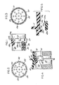
- FIGURE 1 illustrates a one piece plastic molded insert 20 which includes a first plurality of resiliently and radially deflectable fingers 21 disposed around the outside of the insert 20 and a second plurality of resiliently and axially deflectable fingers 22 also disposed on the outside of the insert 20 and adjacent the first plurality of fingers 21.
- the first and second plurality of fingers being an integral part of the one-piece molded insert 20.
- Each of the first plurality of radial fingers 21 includes a free end 21a and an outer surface 21b.
- Each of the second plurality of axial fingers 22 include an axial facing surface 22c.
- Also molded into the insert 20 are a plurality of bores each having contact retaining fingers 26 to retain a contact 30 in the bore.
- FIGURE 2 shows an end view of the insert 20 and illustrates how the axial fingers 22 are arranged completely around the outside of the insert 20. Although in the preferred embodiment the fingers are arranged completely around the outside of the insert 20, fingers spaced 90° apart may also suffice.
- the insert 20 also includes a plurality of axially extending bores 25 which are adapted to receive and retain respective contacts.
- FIGURE 3 illustrates a view of the other end of the insert 20 and illustrates how the radial exending fingers 21 are also arranged around the outside of the insert 20. Although the preferred embodiment shows the radial fingers 21 completely around the outside of the insert 20, fingers spaced 90° apart may also suffice.
- FIGURE 4 illustrates how the insert 20 is mounted within the connector housing 10.
- it includes an external annular flange 11, threads 12 on the forward portion and threads 13 on the rear portion.
- the housing 10 includes an internal annular shoulder 16 and an annular groove 15.
- the annular groove 15 is adapted to receive the radial fingers 21 and axial fingers 22 of the insert 20.
- the fingers 22, which were axially extending, are depressed rearwardly to take up the slack in the groove 15.
- FIGURE 5 illustrates an enlarged portion of the groove 15 in the housing 10 and the insert fingers 21 and 22.
- the groove 15 includes a bottom surface 15b and side surfaces 15a and 15c.
- the bottom surface 15b of the groove 15 is adapted to receive the outer surface 21b of the radially extending finger 21.
- the side surface 15a of the groove 15 is adapted to receive the free end 21a of the radial finger 21.
- the other side surface 15c of the groove 15 is adapted to receive the forwardly facing side surface 22c of the axially extending finger 22.
- the insert 20 is inserted into the rear of the housing 10 until the deflected fingers 21 snap outwardly into position in the groove 15.
- the forward movement of the insert 20 as it is inserted into the housing 10 also causes the axially extending fingers to be deflected rearwardly when they abut against the housing shoulder 15c.
- the first and second plurality of fingers operate to entirely fill the space between sides 15a and 15c of the groove and prevent free axial movement of the insert 20.
Abstract
Description
- This invention relates to electrical connectors and more specifically to the insert within the connector.
- An electrical connector assembly is generally comprised of two separate housings, each having contacts matable with contacts in the other one, the housings are connected together by a coupling member. Each of the housings include an insert of dielectric material provided with multiple openings within which electrical contacts are retained. The insert is generally introduced into the housing from the rear and then held in place by some mechanical means or by chemical bonding. An example of one such connector may be found in U.S. Patent 3,876,275 issued April 8, 1975 and entitled "Arrangement for Retaining Electrical Connector Insert". In electrical connectors where the insert is mechanically connected or chemically bonded to the housing, assembly fixtures, special cleaning, or the application of chemical agents and heating of the assembly is required. Further, in arrangements where the insert is snapped into an undercut within the housing axial movement of the insert is present and extra material, such an epoxy or a resilient material, is necessary to prevent such movement of the insert.
- This invention provides an insert for an electrical connector that may be easily mounted within the connector housing without the need for chemical bonding or for additional mounting members or assembly fixtures to prevent axial movement.
- The invention is an insert for an electrical connector characterized by a first plurality of resiliently and radially
reflectable fingers 21 located on the outside of the insert and a second plurality of resiliently and axiallydeflectable fingers 22 also disposed on the. outside of the insert. Both pluralities offingers - Accordingly, it is an object of this invention to provide an insert that is easily assembled into the connector housing.
- It is another object of this invention to provide an insert for electrical connectors that is comprised of a single integral molded piece that includes the means for mounting the insert inside the connector housing.
- It is another advantage of this invention to provide a one-piece insert for a connector assembly that does not move freely in the axial direction after it is mounted.
-
- FIGURE 1 illustrates an insert incorporating the principles of the invention.
- FIGURE 2 is a front view of the insert shown in FIGURE 1.
- FIGURE 3 is a rear view of the insert shown in FIGURE 1.
- FIGURE 4 is a diagramatic view of the insert shown in FIGURE 1 mounted in a connector housing.
- FIGURE 5 is an enlarged view of the groove in the connector housing shown in FIGURE 4.
- Referring now to the drawings, FIGURE 1 illustrates a one piece plastic molded
insert 20 which includes a first plurality of resiliently and radiallydeflectable fingers 21 disposed around the outside of theinsert 20 and a second plurality of resiliently and axiallydeflectable fingers 22 also disposed on the outside of theinsert 20 and adjacent the first plurality offingers 21. The first and second plurality of fingers being an integral part of the one-piece moldedinsert 20. Each of the first plurality ofradial fingers 21 includes afree end 21a and an outer surface 21b. Each of the second plurality ofaxial fingers 22 include an axial facing surface 22c. Also molded into theinsert 20 are a plurality of bores each havingcontact retaining fingers 26 to retain acontact 30 in the bore. - FIGURE 2 shows an end view of the
insert 20 and illustrates how theaxial fingers 22 are arranged completely around the outside of theinsert 20. Although in the preferred embodiment the fingers are arranged completely around the outside of theinsert 20, fingers spaced 90° apart may also suffice. Theinsert 20 also includes a plurality of axially extendingbores 25 which are adapted to receive and retain respective contacts. - FIGURE 3 illustrates a view of the other end of the
insert 20 and illustrates how the radial exendingfingers 21 are also arranged around the outside of theinsert 20. Although the preferred embodiment shows theradial fingers 21 completely around the outside of theinsert 20, fingers spaced 90° apart may also suffice. - FIGURE 4 illustrates how the
insert 20 is mounted within the connector housing 10. As in most cylindrical connector housings 10, it includes an external annular flange 11, threads 12 on the forward portion and threads 13 on the rear portion. The housing 10 includes an internal annular shoulder 16 and anannular groove 15. Theannular groove 15 is adapted to receive theradial fingers 21 andaxial fingers 22 of theinsert 20. When theinsert 20 is properly mounted in the housing 10, thefingers 22, which were axially extending, are depressed rearwardly to take up the slack in thegroove 15. - FIGURE 5 illustrates an enlarged portion of the
groove 15 in the housing 10 and theinsert fingers groove 15 includes a bottom surface 15b andside surfaces 15a and 15c. The bottom surface 15b of thegroove 15 is adapted to receive the outer surface 21b of the radially extendingfinger 21. Theside surface 15a of thegroove 15 is adapted to receive thefree end 21a of theradial finger 21. The other side surface 15c of thegroove 15 is adapted to receive the forwardly facing side surface 22c of the axially extendingfinger 22. - To mount the
insert 20 in the housing 10 theinsert 20 is inserted into the rear of the housing 10 until thedeflected fingers 21 snap outwardly into position in thegroove 15. The forward movement of theinsert 20 as it is inserted into the housing 10 also causes the axially extending fingers to be deflected rearwardly when they abut against the housing shoulder 15c. The first and second plurality of fingers operate to entirely fill the space betweensides 15a and 15c of the groove and prevent free axial movement of theinsert 20. - While a preferred embodiment of this invention has been disclosed, it will be apparent to those skilled in the art, that changes may be made to the invention as set forth in the appended claims, and in some instances, certain features of the invention may be used to advantage without corresponding use of other features. Accordingly, it is intended that the illustrative and descriptive materials herein will be used to illustrate the principles of the invention and not to limit the scope thereof.
Claims (4)
Applications Claiming Priority (2)
| Application Number | Priority Date | Filing Date | Title |
|---|---|---|---|
| US06/206,769 US4361376A (en) | 1980-11-14 | 1980-11-14 | Electrical connector |
| US206769 | 1980-11-14 |
Publications (2)
| Publication Number | Publication Date |
|---|---|
| EP0052531A1 true EP0052531A1 (en) | 1982-05-26 |
| EP0052531B1 EP0052531B1 (en) | 1984-08-15 |
Family
ID=22767877
Family Applications (1)
| Application Number | Title | Priority Date | Filing Date |
|---|---|---|---|
| EP81401528A Expired EP0052531B1 (en) | 1980-11-14 | 1981-10-02 | Mounting means of an insert in an electrical connector housing |
Country Status (5)
| Country | Link |
|---|---|
| US (1) | US4361376A (en) |
| EP (1) | EP0052531B1 (en) |
| JP (1) | JPS57109268A (en) |
| CA (1) | CA1151259A (en) |
| DE (1) | DE3165571D1 (en) |
Cited By (2)
| Publication number | Priority date | Publication date | Assignee | Title |
|---|---|---|---|---|
| GB2189089A (en) * | 1986-04-14 | 1987-10-14 | Schulte Elektrotech | Connector |
| EP0317925A2 (en) * | 1987-11-25 | 1989-05-31 | Itt Industries, Inc. | Retention and ground plane connector clip |
Families Citing this family (11)
| Publication number | Priority date | Publication date | Assignee | Title |
|---|---|---|---|---|
| DE3302924C3 (en) * | 1983-01-28 | 1995-09-21 | Grote & Hartmann | Electrical connector |
| JPH0138868Y2 (en) * | 1985-07-30 | 1989-11-20 | ||
| US4786261A (en) * | 1987-01-20 | 1988-11-22 | Ramos Jr Phillip M | Electrical connector assembly for a truck-trailer jumper cable |
| DE3823617A1 (en) * | 1988-07-12 | 1990-01-18 | Gore W L & Co Gmbh | METAL HOUSING FOR AN ELECTRICAL CONNECTOR AND CONNECTOR |
| US4985002A (en) * | 1988-10-25 | 1991-01-15 | Preh, Elektrofeinmechanische Werke Jakob Preh, Nachf, Gmbh & Co. | Shielded circular plug connector |
| US5320546A (en) * | 1991-04-16 | 1994-06-14 | The Whitaker Corporation | Electrical connector with interlocked components |
| US5145411A (en) * | 1991-08-14 | 1992-09-08 | Amp Incorporated | Connector insert retention system |
| DE9204386U1 (en) * | 1992-03-31 | 1992-06-25 | Escha Bauelemente Gmbh, 5884 Halver, De | |
| WO1999062145A1 (en) | 1998-05-27 | 1999-12-02 | Tyco Electronics Corporation | Electrical connector with split shells and retention clip and method of assembling the connector |
| US6042428A (en) * | 1998-06-22 | 2000-03-28 | Itt Manufacturing Enterprises, Inc. | Connector insert retention |
| DE102004018103B3 (en) * | 2004-04-14 | 2005-09-08 | U.I. Lapp Gmbh | Connector for signal transmission cable, has carrier unit for signal interface elements arranged in housing cavity |
Citations (3)
| Publication number | Priority date | Publication date | Assignee | Title |
|---|---|---|---|---|
| US2970352A (en) * | 1958-11-03 | 1961-02-07 | Int Harvester Co | Device for supporting tubes in core box assemblies |
| US3477061A (en) * | 1966-06-20 | 1969-11-04 | Bunker Ramo | Contact retention device |
| US3512119A (en) * | 1966-09-20 | 1970-05-12 | Bunker Ramo | Electrical connector |
Family Cites Families (4)
| Publication number | Priority date | Publication date | Assignee | Title |
|---|---|---|---|---|
| US3671921A (en) * | 1970-10-28 | 1972-06-20 | Amp Inc | Multi-contact electrical connector |
| US3970352A (en) * | 1972-09-25 | 1976-07-20 | Bunker Ramo Corporation | Electrical connector having improved contact retention system |
| IL43271A (en) * | 1972-09-27 | 1976-07-30 | Bunker Ramo | Electrical connector |
| US3845452A (en) * | 1972-12-26 | 1974-10-29 | Bendix Corp | Rear release contact retention assembly |
-
1980
- 1980-11-14 US US06/206,769 patent/US4361376A/en not_active Expired - Lifetime
-
1981
- 1981-08-20 CA CA000384275A patent/CA1151259A/en not_active Expired
- 1981-10-02 EP EP81401528A patent/EP0052531B1/en not_active Expired
- 1981-10-02 DE DE8181401528T patent/DE3165571D1/en not_active Expired
- 1981-11-13 JP JP56181270A patent/JPS57109268A/en active Pending
Patent Citations (3)
| Publication number | Priority date | Publication date | Assignee | Title |
|---|---|---|---|---|
| US2970352A (en) * | 1958-11-03 | 1961-02-07 | Int Harvester Co | Device for supporting tubes in core box assemblies |
| US3477061A (en) * | 1966-06-20 | 1969-11-04 | Bunker Ramo | Contact retention device |
| US3512119A (en) * | 1966-09-20 | 1970-05-12 | Bunker Ramo | Electrical connector |
Cited By (4)
| Publication number | Priority date | Publication date | Assignee | Title |
|---|---|---|---|---|
| GB2189089A (en) * | 1986-04-14 | 1987-10-14 | Schulte Elektrotech | Connector |
| GB2189089B (en) * | 1986-04-14 | 1990-03-21 | Schulte Elektrotech | Electrical connector |
| EP0317925A2 (en) * | 1987-11-25 | 1989-05-31 | Itt Industries, Inc. | Retention and ground plane connector clip |
| EP0317925A3 (en) * | 1987-11-25 | 1989-09-20 | Itt Industries Inc. | Retention and ground plane connector clip |
Also Published As
| Publication number | Publication date |
|---|---|
| JPS57109268A (en) | 1982-07-07 |
| DE3165571D1 (en) | 1984-09-20 |
| US4361376A (en) | 1982-11-30 |
| CA1151259A (en) | 1983-08-02 |
| EP0052531B1 (en) | 1984-08-15 |
Similar Documents
| Publication | Publication Date | Title |
|---|---|---|
| US4361376A (en) | Electrical connector | |
| US4389081A (en) | Electrical connector coupling ring | |
| US5389005A (en) | Waterproof electric connector seal member | |
| EP0052530B1 (en) | Electrical connector coupling ring having an integral spring | |
| EP0475415B1 (en) | Multiple pole electrical connector | |
| US4998889A (en) | Electrical connector | |
| US4629269A (en) | Electrical connector with environmental seal | |
| JPH07118346B2 (en) | Sealed electrical connector | |
| EP1168521A2 (en) | Connector | |
| EP0928980B1 (en) | Cap for optical connector | |
| US4941847A (en) | Electrical connector contact retention system | |
| EP0052538A2 (en) | Electrical connector coupling member | |
| US4362349A (en) | Electrical connector housing with integral retention mechanism | |
| US6325669B1 (en) | Electrical connector sealing system | |
| US3461258A (en) | Positive pressure cam type connector assembly and housings therefor | |
| US4387945A (en) | Electrical connector insert | |
| US20190319393A1 (en) | Electrical connector having a metallic inner shell with rear engaging finger situated within an insulative outer cover | |
| US4611880A (en) | Multipiece electrical connector | |
| US4361373A (en) | Electrical connector comprised of plastic | |
| EP4044409A1 (en) | Motor brush, motor and washing machine | |
| CN114696151A (en) | Seal for flat flexible conductors in an electrical connector assembly | |
| US5687836A (en) | Electrical switch assembly actuatable by a rotatable member | |
| US4461526A (en) | Anti-decoupling mechanism for an electrical connector | |
| EP0052540A2 (en) | Molded plastic connector | |
| US11527852B2 (en) | Separable high-voltage connector assembly and manufacturing method therefor |
Legal Events
| Date | Code | Title | Description |
|---|---|---|---|
| PUAI | Public reference made under article 153(3) epc to a published international application that has entered the european phase |
Free format text: ORIGINAL CODE: 0009012 |
|
| 17P | Request for examination filed |
Effective date: 19811016 |
|
| AK | Designated contracting states |
Designated state(s): DE FR GB IT |
|
| ITF | It: translation for a ep patent filed |
Owner name: ING. ZINI MARANESI & C. S.R.L. |
|
| GRAA | (expected) grant |
Free format text: ORIGINAL CODE: 0009210 |
|
| AK | Designated contracting states |
Designated state(s): DE FR GB IT |
|
| PGFP | Annual fee paid to national office [announced via postgrant information from national office to epo] |
Ref country code: FR Payment date: 19840903 Year of fee payment: 4 |
|
| REF | Corresponds to: |
Ref document number: 3165571 Country of ref document: DE Date of ref document: 19840920 |
|
| PGFP | Annual fee paid to national office [announced via postgrant information from national office to epo] |
Ref country code: DE Payment date: 19841018 Year of fee payment: 4 |
|
| ET | Fr: translation filed | ||
| PLBE | No opposition filed within time limit |
Free format text: ORIGINAL CODE: 0009261 |
|
| STAA | Information on the status of an ep patent application or granted ep patent |
Free format text: STATUS: NO OPPOSITION FILED WITHIN TIME LIMIT |
|
| 26N | No opposition filed | ||
| PG25 | Lapsed in a contracting state [announced via postgrant information from national office to epo] |
Ref country code: GB Effective date: 19881002 |
|
| PG25 | Lapsed in a contracting state [announced via postgrant information from national office to epo] |
Ref country code: FR Free format text: LAPSE BECAUSE OF NON-PAYMENT OF DUE FEES Effective date: 19890630 |
|
| PG25 | Lapsed in a contracting state [announced via postgrant information from national office to epo] |
Ref country code: DE Effective date: 19890701 |
|
| GBPC | Gb: european patent ceased through non-payment of renewal fee | ||
| REG | Reference to a national code |
Ref country code: FR Ref legal event code: ST |