EP0052350B1 - Process for reinforcing the edges of a band - Google Patents
Process for reinforcing the edges of a band Download PDFInfo
- Publication number
- EP0052350B1 EP0052350B1 EP81109650A EP81109650A EP0052350B1 EP 0052350 B1 EP0052350 B1 EP 0052350B1 EP 81109650 A EP81109650 A EP 81109650A EP 81109650 A EP81109650 A EP 81109650A EP 0052350 B1 EP0052350 B1 EP 0052350B1
- Authority
- EP
- European Patent Office
- Prior art keywords
- reinforcing element
- spirals
- band
- undulations
- reinforcing
- Prior art date
- Legal status (The legal status is an assumption and is not a legal conclusion. Google has not performed a legal analysis and makes no representation as to the accuracy of the status listed.)
- Expired
Links
Images


Classifications
-
- D—TEXTILES; PAPER
- D21—PAPER-MAKING; PRODUCTION OF CELLULOSE
- D21F—PAPER-MAKING MACHINES; METHODS OF PRODUCING PAPER THEREON
- D21F1/00—Wet end of machines for making continuous webs of paper
- D21F1/0027—Screen-cloths
- D21F1/0072—Link belts
Definitions
- the present invention relates to a method of reinforcing the edge of a strip consisting of spirals assembled together by their overlapping or by joining rods in which a reinforcing element is introduced at the edge of the strip which is supported on the ends of the spirals.
- the ends of the joining rods are used to make the reinforcement and a selvedge wire is added thereto.
- the method according to the invention does not have this drawback is characterized in that said element consists of a wire consisting of a series of the worst or of undulations of which at least one turn or undulation is introduced inside each spiral according to their axial direction.
- said edge of the strip parallel to the longitudinal axis. It is thus possible to catch up with the edges of the strips which, because of the variations in the stresses during assembly and / or thermofixing, are not very straight.
- the method according to the invention allows a rectification of the edges which obviously does not allow the known method using the ends of the rods as reinforcing elements.
- the positioning of the reinforcing element inside the spirals of the strip is further reinforced by coating the edge of the strip over a width L greater than the penetration of the turns of the reinforcing element.
- a conveyor belt 1 consists of spirals 2 and 3 arranged in the transverse direction relative to the longitudinal axis of the belt. These spirals 2 and 3 formed respectively in the right direction D and the left direction G are assembled by joining rods 5 made of synthetic material for example.
- the edge of the strip is cut straight parallel to the longitudinal axis.
- the ends of the cut spirals are at the same level as the end of the rod 5 connecting the spirals.
- the turns of a reinforcing spiral 10 are introduced inside the spirals in the channel left free and at the edge of the strip.
- the bottom 11 of a loop of the reinforcing spiral is applied against the ends e i spirals of the strip and e 2 of the junction ring.
- the turns 12 of the reinforcing spiral 10 are maintained inside the spirals 2, 3 of the strip by friction against these spirals.
- an additional reinforcement of the selvedge is obtained by introducing a reinforcing wire 13 into the bottom 11 of the reinforcement turns, between the ends e 1 of the spirals of the strip and the reinforcement spiral 10.
- the positioning of the reinforcement element 10 inside the spirals 2 and 3 of the strip is further reinforced by coating the edge 18 of the strip over a width L greater than the penetration of the spirals 12 of the reinforcement element 10 (fig 7).
- the width of the turns 12 of the reinforcing element 10 must be sufficient for them to penetrate well inside the selvedges 18, a width of 20 mm is suitable.
- the steps of the turns 12 depend on the number of spirals 2 and 3 joined in the longitudinal direction of the strip.
- the thickness of the turns 12 of the reinforcing element 10 depends on the space available inside the spirals 2 and 3 of the strip. Too much thickness prevents its introduction into the spirals of the strip. Too small a thickness will not block the reinforcing element 10 inside the spirals of the strip.
- the reinforcing element 10 may consist of monofilaments, multifilaments, impregnated braids, metallic threads. It can be covered with multifilament threads. It can be flocked to improve the adhesion of the selvedge impregnation adhesive.
- reinforcement element 10 of the selvedges can take different forms.
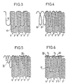
- FIG. 3 represents a variant in which the reinforcing element has a shape having pronounced undulations in a zigzag or accordion folding.
- FIG. 5 represents a variant in which the reinforcing element comprises turns 19 of unequal lengths in each spiral of the strip to facilitate their introduction into the selvedges.
- an additional reinforcement wire 13 can be introduced at the bottom 11 of the reinforcement coil, in a longitudinal direction, to improve the quality of the reinforcement.
- This wire can be a monofilament, a multifilament, a single or twisted or cabled fabric thread, a chain.
- FIG. 6 shows a variant of FIG. 2 in which a chain stitch reinforcement 20 connects the turns of the reinforcement element on the selvedge side; the chain, the meshes of which are formed around the spiral wires of the reinforcing element, acts as a reinforcement and maintains the correct spacing between the turns of the reinforcing element.
- Each turn of the reinforcing element can be distant from the previous one by a value equal to the pitch of the spirals of the strip in the longitudinal direction.
- the strip can consist of spirals assembled together by their nesting without the use of rods.
- the reinforcing element 10 which is introduced into the spirals 2 and 3 at the edge of the strip, is supported only on the ends e, of the turns cut from the spirals.
Abstract
Description
La présente invention a trait à un procédé de renforcement de lisière de bande constituée de spirales assemblées entre elles par leur imbrication ou par des joncs de jonctionnement dans lequel on introduit en lisière de la bande un élément de renforcement qui s'appuie sur les extrémités des spirales.The present invention relates to a method of reinforcing the edge of a strip consisting of spirals assembled together by their overlapping or by joining rods in which a reinforcing element is introduced at the edge of the strip which is supported on the ends of the spirals.
Un tel procédé est décrit dans le document CH-A-610 273.Such a process is described in document CH-A-610 273.
Dans le procédé connu on utilise les extrémités des joncs de jonctionnement pour réaliser le renforcement et on y ajoute un fil en lisière.In the known method, the ends of the joining rods are used to make the reinforcement and a selvedge wire is added thereto.
Ce procédé est malaisé à mettre en oeuvre puisqu'il faut prédéformer au moins une extrémité des joncs.This process is difficult to implement since it is necessary to preform at least one end of the rods.
Le procédé selon l'invention ne présentant pas cet inconvénient est caractérisé en ce que ledit élément est constitué par un fil constitué d'une suite des pires ou d'ondulations dont au moins une spire ou ondulation est introduite à l'intérieur de chaque spirale selon leur direction axiale. Selon une réalisation particulière de l'invention avant d'introduire l'élément de renforcement en coupe la lisière de la bande parallèlement à l'axe longitudinal. On peut ainsi rattraper les bords des bandes qui, à cause des variations dans le contraintes lors de l'assemblage et/ou de la thermofi- xation, ne sont pas très droits.The method according to the invention does not have this drawback is characterized in that said element consists of a wire consisting of a series of the worst or of undulations of which at least one turn or undulation is introduced inside each spiral according to their axial direction. According to a particular embodiment of the invention before introducing the reinforcing element in section the edge of the strip parallel to the longitudinal axis. It is thus possible to catch up with the edges of the strips which, because of the variations in the stresses during assembly and / or thermofixing, are not very straight.
Le procédé selon l'invention permet une rectification des bords ce que ne permet évidemment pas le procédé connu utilisant les extrémités des joncs comme éléments de renforcement.The method according to the invention allows a rectification of the edges which obviously does not allow the known method using the ends of the rods as reinforcing elements.
Le positionnement de l'élément de renforcement à l'intérieur des spirales de la bande est encore renforcé par l'enduction de la lisière de la bande sur une largeur L supérieure à la pénétration des spires de l'élément de renforcement.The positioning of the reinforcing element inside the spirals of the strip is further reinforced by coating the edge of the strip over a width L greater than the penetration of the turns of the reinforcing element.
Pour accroître le renforcement on peut introduire au fond des spires du fil de renforcement un fil de renfort supplémentaire de sens longitudinal. L'invention va être décrite plus en détail en se référant à des modes de réalisation particuliers cités à titre d'exemple et illustrés sur les dessins annexés.
- La figure 1 représente un mode préféré de réalisation du renforcement de lisière de bande selon l'invention.
- La figure 2 représente le même mode avec un élément de renfort supplémentaire.
- La figure 3 représente une variante de la figure 1.
- Les figures 4 et 5 représentent d'autres variantes.
- La figure 6 représente le mode de la figure 1 avec un autre élément de renfort supplémentaire.
- La figure 7 est une vue de dessus de la bande selon la figure 1 après enduction d'une lisière.
- Figure 1 shows a preferred embodiment of the strip edge reinforcement according to the invention.
- Figure 2 shows the same mode with an additional reinforcing element.
- FIG. 3 represents a variant of FIG. 1.
- Figures 4 and 5 show other variants.
- Figure 6 shows the mode of Figure 1 with another additional reinforcing element.
- Figure 7 is a top view of the strip according to Figure 1 after coating a selvedge.
Dans les formes de réalisation représentées une bande transporteuse 1 est constituée de spirales 2 et 3 disposées dans le sens transversal par rapport à l'axe longitudinal de la bande.Ces spirales 2 et 3 formées respectivement dans le sens droite D et le sens gauche G sont assemblées par des joncs de jonctionnement 5 en matière synthétique par exemple.In the embodiments shown a
La lisière de la bande est coupée droite parallèlement à l'axe longitudinal. Les extrémités des spirales coupées sont au même niveau que l'extrémité du jonc 5 reliant les spirales.The edge of the strip is cut straight parallel to the longitudinal axis. The ends of the cut spirals are at the same level as the end of the
A l'intérieur des spirales dans le canal laissé libre et en lisière de la bande, on introduit les spires d'une spirale de renforcement 10. Le fond 11 d'une boucle de la spirale de renforcement s'applique contre les extrémités ei des spirales de la bande et e2 du jonc de jonctionnement. Les spires 12 de la spirale de renforcement 10 se maintiennent à l'intérieur des spirales 2, 3 de la bande par frottement contre ces spirales.Inside the spirals in the channel left free and at the edge of the strip, the turns of a reinforcing
Dans la figure 2 un renforcement supplémentaire de la lisière est obtenu en introduisant un fil de renfort 13 dans le fond 11 des spires de renforcement, entre les extrémités e1 des spirales de la bande et la spirale de renforcement 10. Le positionnement de l'élément de renforcement 10 à l'intérieur des spirales 2 et 3 de la bande est encore renforcé par l'enduction de la lisière 18 de la bande sur une largeur L supérieure à la pénétration des spirales 12 de l'élément de renforcement 10 (fig. 7).In FIG. 2, an additional reinforcement of the selvedge is obtained by introducing a reinforcing
La largeur des spires 12 de l'élément de renforcement 10 doit être suffisante pour qu'elles péné- trent bien à l'intérieur des lisières 18, une largeur de 20 mm convient.The width of the
Les pas des spires 12 dépend du nombre de spirales 2 et 3 jonctionnées dans le sens longitudinal de la bande.The steps of the
L'épaisseur des spires 12 de l'élément de renforcement 10 dépend de l'espace disponible à l'intérieur des spirales 2 et 3 de la bande. Une épaisseur trop forte empêche son introduction dans les spirales de la bande. Une épaisseur trop faible ne bloquera pas l'élément de renforcement 10 à l'intérieur des spirales de la bande. L'élément de renforcement 10 peut être constitué de mono- filaments, de multifilaments, de tressses imprégnées, de fils métalliques. Il peut être guipé de fils multifilaments. Il peut être floqué pour améliorer l'adhérence de la colle d'imprégnation des lisières.The thickness of the
Dans des variantes l'élément de renforcement 10 des lisières peut prendre différentes formes.In variants the
La figure 3 représente une variante dans laquelle l'élément de renforcement a une forme présentant des ondulations prononcées 15 en zig-zag ou pliage accordéon.FIG. 3 represents a variant in which the reinforcing element has a shape having pronounced undulations in a zigzag or accordion folding.
Dans le cas de la figure 4 deux spires successives 16, 17 de l'élément de renforcement sont introduites dans chaque spirale de la bande pour améliorer la tenue de l'élément de renforcement par la colle d'imprégnation des lisiéres.In the case of FIG. 4, two
La figure 5 représente une variante dans laquelle l'élément de renforcement comporte des spires 19 de longueurs inégales dans chaque spirale de la bande pour faciliter leur introduction dans les lisières.FIG. 5 represents a variant in which the reinforcing element comprises turns 19 of unequal lengths in each spiral of the strip to facilitate their introduction into the selvedges.
Comme on l'a vu pour la figure 2, on peut introduire au fond 11 de la spire de renforcement un fil de renfort supplémentaire 13, de sens longitudinal, pour améliorer la qualité du renfort. Ce fil peut être un monofilament, un multifilament, un fil en tissu simple ou retors ou câblé, une chaîne.As we have seen for FIG. 2, an
La figure 6 représente une variante de la figure 2 dans laquelle un renfort en point de chaînette 20 relie entre elles les spires de l'élément de renforcement côté lisière; la chaînette dont les mailles sont formées autour des fils en spirale de l'élément de renforcement, joue le rôle de renfort et maintient le bon écartement entre les spires de l'élément de renforcement. Chaque spire de l'élément de renforcement peut être distante de la précédente d'une valeur égale au pas des spirales de la bande dans le sens longitudinal.FIG. 6 shows a variant of FIG. 2 in which a
La bande peut être constituée de spirales assemblées entre elles par leur imbrication sans utilisation de joncs. Dans ce cas l'élément de renforcement 10 qui est introduit dans les spirales 2 et 3 en lisière de la bande, s'appuie seulement sur les extrémités e, des spires coupées des spirales.The strip can consist of spirals assembled together by their nesting without the use of rods. In this case the reinforcing
Claims (7)
Priority Applications (1)
| Application Number | Priority Date | Filing Date | Title |
|---|---|---|---|
| AT81109650T ATE13776T1 (en) | 1980-11-19 | 1981-11-12 | PROCEDURE FOR REINFORCING THE EDGES OF A TAPE. |
Applications Claiming Priority (2)
| Application Number | Priority Date | Filing Date | Title |
|---|---|---|---|
| FR8024531 | 1980-11-19 | ||
| FR8024531A FR2494320A1 (en) | 1980-11-19 | 1980-11-19 | METHOD AND DEVICE FOR STRENGTHENING BAND EDGE |
Publications (2)
| Publication Number | Publication Date |
|---|---|
| EP0052350A1 EP0052350A1 (en) | 1982-05-26 |
| EP0052350B1 true EP0052350B1 (en) | 1985-06-12 |
Family
ID=9248125
Family Applications (1)
| Application Number | Title | Priority Date | Filing Date |
|---|---|---|---|
| EP81109650A Expired EP0052350B1 (en) | 1980-11-19 | 1981-11-12 | Process for reinforcing the edges of a band |
Country Status (5)
| Country | Link |
|---|---|
| EP (1) | EP0052350B1 (en) |
| AT (1) | ATE13776T1 (en) |
| DE (1) | DE3170953D1 (en) |
| ES (1) | ES269283Y (en) |
| FR (1) | FR2494320A1 (en) |
Families Citing this family (4)
| Publication number | Priority date | Publication date | Assignee | Title |
|---|---|---|---|---|
| DE3315696A1 (en) * | 1983-04-29 | 1984-10-31 | Württembergische Filztuchfabrik D. Geschmay GmbH, 7320 Göppingen | LINKED BAND, e.g. FOR PAPER PRODUCTION |
| DE3501981A1 (en) * | 1985-01-22 | 1986-07-24 | Hermann Wangner Gmbh & Co Kg, 7410 Reutlingen | SPIRAL LINK WITH PROTECTED EDGES |
| DE3914534C1 (en) * | 1989-05-02 | 1990-10-18 | Thomas Josef Heimbach Gmbh & Co, 5160 Dueren, De | |
| DE3914533A1 (en) * | 1989-05-02 | 1990-11-08 | Heimbach Gmbh Thomas Josef | TAPE FOR PAPER MACHINES |
Family Cites Families (1)
| Publication number | Priority date | Publication date | Assignee | Title |
|---|---|---|---|---|
| CH610273A5 (en) * | 1975-10-02 | 1979-04-12 | Munzinger Conrad & Cie Ag | Flat formation acting as a wire link conveyor |
-
1980
- 1980-11-19 FR FR8024531A patent/FR2494320A1/en active Granted
-
1981
- 1981-11-12 EP EP81109650A patent/EP0052350B1/en not_active Expired
- 1981-11-12 AT AT81109650T patent/ATE13776T1/en not_active IP Right Cessation
- 1981-11-12 DE DE8181109650T patent/DE3170953D1/en not_active Expired
- 1981-11-18 ES ES1981269283U patent/ES269283Y/en not_active Expired
Also Published As
| Publication number | Publication date |
|---|---|
| DE3170953D1 (en) | 1985-07-18 |
| ES269283U (en) | 1983-08-01 |
| FR2494320A1 (en) | 1982-05-21 |
| EP0052350A1 (en) | 1982-05-26 |
| ES269283Y (en) | 1984-02-16 |
| FR2494320B1 (en) | 1982-11-26 |
| ATE13776T1 (en) | 1985-06-15 |
Similar Documents
| Publication | Publication Date | Title |
|---|---|---|
| EP0198776B1 (en) | Textile reinforcing layer useful in the manufacture of laminated articles, and laminated articles containing such a reinforcing layer | |
| EP0193478B1 (en) | Textile reinforcement for the manufacture of layered products | |
| EP0052350B1 (en) | Process for reinforcing the edges of a band | |
| FR2711679A1 (en) | A wire yarn for smooth weaving smooth provided with such an eyelet and its method of realization. | |
| US6461713B2 (en) | Carrier with set down elongation reducing member | |
| EP1155186B1 (en) | Junction with symmetrical weave for woven band with asymmetric weave | |
| FR2477585A1 (en) | WEAVING STRIP AND USE OF SUCH A SMOOTH TO FORM A PAIR OF SMOOTH DOUBLE ROWS OF EYETS | |
| EP1203115B1 (en) | Sound absorbent protective sleeve | |
| FR2499107A1 (en) | Woven double ribbon with single selvedge - has weft laid on bias | |
| EP0124083B1 (en) | Woven web, especially for the paper industry | |
| EP0135944A2 (en) | Method and device for stringing tennis rackets | |
| EP0046465A1 (en) | Fastening ribbon provided with fungiform elements | |
| EP1384401B1 (en) | Method and trawl-type net facilitating the installation of the trawl-type net on the mounting bar of a sewing machine | |
| FR2504173A1 (en) | METAL REINFORCEMENT STRIPS FOR CONCRETE COATING OF UNDERWATER CONDUITS | |
| EP0106775B1 (en) | Method of making synthetic fabrics, in particular for paper-making machines, and synthetic fabric made by the method | |
| EP0243251B1 (en) | Deformable metallic frame for a sealing strip, and sealing strip using such a metallic frame | |
| EP0857410B1 (en) | Cutting line for bush- and edgetrimmer | |
| EP0516560A1 (en) | Textile reinforcement for making layered structures and method for its manufacture | |
| JPS6274815A (en) | Spiral link belt with filling helix wound around pintle wire | |
| WO2003105298A1 (en) | Method for making a partitioned textile cladding and resulting partitioned textile cladding | |
| FR2522027A1 (en) | Reinforcing fabric for composite materials - having stitch-bonded overlapping zigzag arrays of yarns for diagonal strength | |
| BE884906A (en) | TAPE TO READ. | |
| FR2672278A1 (en) | METHOD AND DEVICE FOR CONNECTING THE END OF TWO WIRE ASSEMBLIES. | |
| LU82790A1 (en) | REINFORCEMENT STRIP | |
| EP0179003A1 (en) | Device for limiting a thread balloon, for instance during unwinding, throwing or twisting operations |
Legal Events
| Date | Code | Title | Description |
|---|---|---|---|
| PUAI | Public reference made under article 153(3) epc to a published international application that has entered the european phase |
Free format text: ORIGINAL CODE: 0009012 |
|
| AK | Designated contracting states |
Designated state(s): AT BE CH DE FR GB IT NL SE |
|
| 17P | Request for examination filed |
Effective date: 19821102 |
|
| ITF | It: translation for a ep patent filed |
Owner name: JACOBACCI & PERANI S.P.A. |
|
| GRAA | (expected) grant |
Free format text: ORIGINAL CODE: 0009210 |
|
| AK | Designated contracting states |
Designated state(s): AT BE CH DE FR GB IT LI NL SE |
|
| REF | Corresponds to: |
Ref document number: 13776 Country of ref document: AT Date of ref document: 19850615 Kind code of ref document: T |
|
| REF | Corresponds to: |
Ref document number: 3170953 Country of ref document: DE Date of ref document: 19850718 |
|
| PLBE | No opposition filed within time limit |
Free format text: ORIGINAL CODE: 0009261 |
|
| STAA | Information on the status of an ep patent application or granted ep patent |
Free format text: STATUS: NO OPPOSITION FILED WITHIN TIME LIMIT |
|
| 26N | No opposition filed | ||
| PGFP | Annual fee paid to national office [announced via postgrant information from national office to epo] |
Ref country code: CH Payment date: 19920917 Year of fee payment: 12 |
|
| PGFP | Annual fee paid to national office [announced via postgrant information from national office to epo] |
Ref country code: BE Payment date: 19921001 Year of fee payment: 12 |
|
| PGFP | Annual fee paid to national office [announced via postgrant information from national office to epo] |
Ref country code: AT Payment date: 19921030 Year of fee payment: 12 |
|
| ITTA | It: last paid annual fee | ||
| PGFP | Annual fee paid to national office [announced via postgrant information from national office to epo] |
Ref country code: NL Payment date: 19921130 Year of fee payment: 12 |
|
| PGFP | Annual fee paid to national office [announced via postgrant information from national office to epo] |
Ref country code: SE Payment date: 19930922 Year of fee payment: 13 Ref country code: DE Payment date: 19930922 Year of fee payment: 13 |
|
| PGFP | Annual fee paid to national office [announced via postgrant information from national office to epo] |
Ref country code: GB Payment date: 19931022 Year of fee payment: 13 |
|
| PG25 | Lapsed in a contracting state [announced via postgrant information from national office to epo] |
Ref country code: AT Effective date: 19931112 |
|
| PG25 | Lapsed in a contracting state [announced via postgrant information from national office to epo] |
Ref country code: LI Effective date: 19931130 Ref country code: CH Effective date: 19931130 Ref country code: BE Effective date: 19931130 |
|
| BERE | Be: lapsed |
Owner name: COFPA CIE DES FEUTRES POUR PAPETERIES ET DES TISS Effective date: 19931130 |
|
| PG25 | Lapsed in a contracting state [announced via postgrant information from national office to epo] |
Ref country code: NL Effective date: 19940601 |
|
| NLV4 | Nl: lapsed or anulled due to non-payment of the annual fee | ||
| REG | Reference to a national code |
Ref country code: CH Ref legal event code: PL |
|
| PG25 | Lapsed in a contracting state [announced via postgrant information from national office to epo] |
Ref country code: GB Effective date: 19941112 |
|
| PG25 | Lapsed in a contracting state [announced via postgrant information from national office to epo] |
Ref country code: SE Effective date: 19941113 |
|
| EAL | Se: european patent in force in sweden |
Ref document number: 81109650.2 |
|
| GBPC | Gb: european patent ceased through non-payment of renewal fee |
Effective date: 19941112 |
|
| PG25 | Lapsed in a contracting state [announced via postgrant information from national office to epo] |
Ref country code: DE Effective date: 19950801 |
|
| EUG | Se: european patent has lapsed |
Ref document number: 81109650.2 |
|
| PGFP | Annual fee paid to national office [announced via postgrant information from national office to epo] |
Ref country code: FR Payment date: 19961105 Year of fee payment: 16 |
|
| PG25 | Lapsed in a contracting state [announced via postgrant information from national office to epo] |
Ref country code: FR Free format text: THE PATENT HAS BEEN ANNULLED BY A DECISION OF A NATIONAL AUTHORITY Effective date: 19971130 |
|
| REG | Reference to a national code |
Ref country code: FR Ref legal event code: ST |