EP0052091A1 - Schutzvorrichtung gegen Lichtbogen-Überströme - Google Patents
Schutzvorrichtung gegen Lichtbogen-Überströme Download PDFInfo
- Publication number
- EP0052091A1 EP0052091A1 EP81870046A EP81870046A EP0052091A1 EP 0052091 A1 EP0052091 A1 EP 0052091A1 EP 81870046 A EP81870046 A EP 81870046A EP 81870046 A EP81870046 A EP 81870046A EP 0052091 A1 EP0052091 A1 EP 0052091A1
- Authority
- EP
- European Patent Office
- Prior art keywords
- current
- electrode
- phase
- arc
- transducer
- Prior art date
- Legal status (The legal status is an assumption and is not a legal conclusion. Google has not performed a legal analysis and makes no representation as to the accuracy of the status listed.)
- Withdrawn
Links
- 230000008034 disappearance Effects 0.000 claims abstract description 4
- 229920006395 saturated elastomer Polymers 0.000 claims abstract description 3
- 238000004804 winding Methods 0.000 claims description 16
- 230000008878 coupling Effects 0.000 claims description 6
- 238000010168 coupling process Methods 0.000 claims description 6
- 238000005859 coupling reaction Methods 0.000 claims description 6
- 238000009434 installation Methods 0.000 claims description 5
- 238000006073 displacement reaction Methods 0.000 claims 1
- 230000009471 action Effects 0.000 description 10
- 230000000670 limiting effect Effects 0.000 description 9
- 238000005259 measurement Methods 0.000 description 7
- 238000004070 electrodeposition Methods 0.000 description 5
- 230000033228 biological regulation Effects 0.000 description 3
- 230000004907 flux Effects 0.000 description 3
- 230000004927 fusion Effects 0.000 description 3
- 238000003780 insertion Methods 0.000 description 3
- 230000037431 insertion Effects 0.000 description 3
- 238000000034 method Methods 0.000 description 3
- 230000008569 process Effects 0.000 description 3
- 230000009467 reduction Effects 0.000 description 3
- 230000004044 response Effects 0.000 description 3
- 238000006243 chemical reaction Methods 0.000 description 2
- 230000007423 decrease Effects 0.000 description 2
- 238000010891 electric arc Methods 0.000 description 2
- 206010063493 Premature ageing Diseases 0.000 description 1
- 208000032038 Premature aging Diseases 0.000 description 1
- 241000219094 Vitaceae Species 0.000 description 1
- 241000219095 Vitis Species 0.000 description 1
- 235000009754 Vitis X bourquina Nutrition 0.000 description 1
- 235000012333 Vitis X labruscana Nutrition 0.000 description 1
- 235000014787 Vitis vinifera Nutrition 0.000 description 1
- 230000021615 conjugation Effects 0.000 description 1
- 238000010276 construction Methods 0.000 description 1
- 238000010586 diagram Methods 0.000 description 1
- 230000000694 effects Effects 0.000 description 1
- 238000007499 fusion processing Methods 0.000 description 1
- 235000021021 grapes Nutrition 0.000 description 1
- 230000006698 induction Effects 0.000 description 1
- 238000012423 maintenance Methods 0.000 description 1
- 238000002844 melting Methods 0.000 description 1
- 230000008018 melting Effects 0.000 description 1
- 230000004048 modification Effects 0.000 description 1
- 238000012986 modification Methods 0.000 description 1
- 230000007935 neutral effect Effects 0.000 description 1
- 230000035699 permeability Effects 0.000 description 1
- 238000004321 preservation Methods 0.000 description 1
- 230000001105 regulatory effect Effects 0.000 description 1
- 238000004904 shortening Methods 0.000 description 1
- 230000001960 triggered effect Effects 0.000 description 1
Images

Classifications
-
- H—ELECTRICITY
- H05—ELECTRIC TECHNIQUES NOT OTHERWISE PROVIDED FOR
- H05B—ELECTRIC HEATING; ELECTRIC LIGHT SOURCES NOT OTHERWISE PROVIDED FOR; CIRCUIT ARRANGEMENTS FOR ELECTRIC LIGHT SOURCES, IN GENERAL
- H05B7/00—Heating by electric discharge
- H05B7/02—Details
- H05B7/144—Power supplies specially adapted for heating by electric discharge; Automatic control of power, e.g. by positioning of electrodes
-
- H—ELECTRICITY
- H01—ELECTRIC ELEMENTS
- H01F—MAGNETS; INDUCTANCES; TRANSFORMERS; SELECTION OF MATERIALS FOR THEIR MAGNETIC PROPERTIES
- H01F29/00—Variable transformers or inductances not covered by group H01F21/00
- H01F29/14—Variable transformers or inductances not covered by group H01F21/00 with variable magnetic bias
- H01F29/146—Constructional details
-
- H—ELECTRICITY
- H02—GENERATION; CONVERSION OR DISTRIBUTION OF ELECTRIC POWER
- H02H—EMERGENCY PROTECTIVE CIRCUIT ARRANGEMENTS
- H02H9/00—Emergency protective circuit arrangements for limiting excess current or voltage without disconnection
- H02H9/02—Emergency protective circuit arrangements for limiting excess current or voltage without disconnection responsive to excess current
- H02H9/021—Current limitation using saturable reactors
-
- H—ELECTRICITY
- H01—ELECTRIC ELEMENTS
- H01F—MAGNETS; INDUCTANCES; TRANSFORMERS; SELECTION OF MATERIALS FOR THEIR MAGNETIC PROPERTIES
- H01F29/00—Variable transformers or inductances not covered by group H01F21/00
- H01F29/14—Variable transformers or inductances not covered by group H01F21/00 with variable magnetic bias
- H01F2029/143—Variable transformers or inductances not covered by group H01F21/00 with variable magnetic bias with control winding for generating magnetic bias
-
- Y—GENERAL TAGGING OF NEW TECHNOLOGICAL DEVELOPMENTS; GENERAL TAGGING OF CROSS-SECTIONAL TECHNOLOGIES SPANNING OVER SEVERAL SECTIONS OF THE IPC; TECHNICAL SUBJECTS COVERED BY FORMER USPC CROSS-REFERENCE ART COLLECTIONS [XRACs] AND DIGESTS
- Y02—TECHNOLOGIES OR APPLICATIONS FOR MITIGATION OR ADAPTATION AGAINST CLIMATE CHANGE
- Y02P—CLIMATE CHANGE MITIGATION TECHNOLOGIES IN THE PRODUCTION OR PROCESSING OF GOODS
- Y02P10/00—Technologies related to metal processing
- Y02P10/25—Process efficiency
Definitions
- Some of these devices consist in regulating the arc impedance by adjusting the position of the electrodes.
- the electrode In arc furnace installations equipped with this device, the electrode is automatically wound up when the current flowing through it is excessive.
- These devices, modifying the position of the electrodes, are slow in their intervention and their lack of flexibility often leads to defusing the arc. The arc must then re-strike and this results in a loss of time and a reduction in productivity harmful to the economical operation of arc furnaces.
- the most sophisticated devices act, for example in the event of a short circuit on an electrode, both on the position of the electrode and on the value of the electrode current.
- some use electro-mechanical devices whose response time is of the order of ten periods during which the electrodes, subjected to an excessive current, rapidly degrade.
- Still others use thyristor devices which, by their mode of intervention, introduce harmonics of current which are difficult to control.
- the present invention overcomes these drawbacks by setting as primary objective the maximum preservation of the electrodes by an intervention approaching as much as possible the ideal protection.
- Figure 1 shows the interest of an extremely fast intervention by a diagram giving the quantitative distribution of the arcs according to the value of the current of these arcs.
- In 1 2 is located the value of the threshold fixed as maximum current tolerated in the electrode; subsequently called second setpoint,
- the device for protection against excessive arcing currents acts by inserting, in the electrical circuit, a current limiting device with instantaneous intervention, whose action is proportional to the difference observed and which coordinates its action with an electrode position regulator.
- the current limiting device acts by instantaneous insertion of the reactive power necessary to limit the current according to a second setpoint setting a current threshold slightly higher than the nominal value. In the absence of overcurrent, this reactive power is reduced to a minimum value.
- the instantaneous intervention is exercised continuously and is automatically erased when the ascent of the electrode substitutes an increase in resistance of the arc to the increase in inductance transiently produced.
- the operation of the proposed protection device can be summarized in three distinct phases.
- the first phase corresponds to a normal course of melting in the arc furnace; for example, there is no landslide on the electrodes nor in the immediate vicinity therefore there is no excessive current flowing through the electrodes.
- the current flowing through the electrode deviates from the nominal value, set in a first setpoint while remaining below the threshold set in a second setpoint to trigger the intervention of the current limiter, only the electrode position regulator corrects this difference by modifying the electrode position at normal speed. In this case, the current limiting device is inoperative and its presence in the electric power circuit practically does not disturb the latter.
- the second phase is that which characterizes the intervention of the current limiting device.
- the current limiting device intervenes to bring the electrode current to this threshold and thus to avoid the aforementioned harmful consequences.
- the last phase starts when the position of the electrode is such that the resistance of the arc can, by itself, limit the current flowing through it to its nominal value. From this moment, the action of the current limiting device ceases and the installation regains all the active power necessary to continue the fusion process.
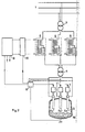
- FIG. 2 represents an embodiment, given by way of example, in which an electrical energy network 1 supplies an electric furnace with arc 2 via a step-down transformer 3 and an oven transformer 4.
- An electrical circuit connects each electrode 5 of the arc oven 2 to the secondary winding of the oven transformer 4.
- a current limiting device 6 is inserted into each phase of the circuit connecting the secondary of the step-down transformer 3 and the primary of the oven transformer 4.
- the electrodes 5 can be raised or lowered by motors 7 controlled by a position regulator 8
- the combined actions of the current limiter 6 and the position regulator 8 are provided by a coordinator 9, a first setpoint imposes the nominal current and a second setpoint sets the value maximum of the current tolerated in each electrode 5. Between the coordinator 9 and the current limiter 6 is inserted a repeater of order 10 whose role will be specified later.
- the current limiter is preferably a single-phase transducer 6 with series coupling inserted in each phase of the supply circuit of the arc furnace 2.
- transducer is meant a symmetrical mounting of two magnetic cores with variable saturation arranged so as to avoid the induction of electromotive force in the control winding.
- FIG. 3 The constitution of the single-phase transducer with series coupling is shown diagrammatically in FIG. 3.
- This device consists of two magnetic circuits 11, each having a saturable core 12 and an unsaturated return circuit 13.
- Two alternative windings 14 each arranged around the saturable core 12 are connected between them in series and in opposition.
- a continuous current winding 15 common to the two magnetic circuits 11 surrounds the two alternating windings 14 and constitutes the control winding.
- the essential function of the tightly coupled single-phase transducer is to limit the arc current as soon as it exceeds the second setpoint of the coordinator 9. This result is obtained by acting on the primary current of the furnace transformer 4 which, by magnetic coupling acts
- the coordinator 9 is responsible for achieving the conjugation between two different actions acting simultaneously when the electrode current becomes excessive.
- One of these actions the insertion of reactive power, is immediate and limits the electrode current as soon as it exceeds the threshold of the second setpoint of the coordinator 9, fixed for example at a value of ten percent higher. at face value.
- the other action raising the electrode to lengthen the arc and increase its resistance, is ordered as soon as the electrode current deviates from the nominal value displayed as the first setpoint in the coordinator 9.
- the power windings of the transducer 6 are traversed by the alternating current and constitute coils of ampere-turns whose total magnetomotor force plays the role of measured image magnitude.
- the second winding of the transducer, the control winding, is crossed by a constant direct current proportional to the current theoretical electrode.
- the proportionality constant of this direct current is basically greater than 1 so as to completely saturate the magnetic core of the transducer during normal operation.
- the specific objective is to render the transducer inoperative as long as the arc currents do not exceed a predetermined limit.
- the transducer therefore intervenes from a threshold determined by the increase in its impedance which limits the overcurrents, while below this threshold the device remains inoperative.
- the winding of the transducer supplied with DC as explained above constitutes a coil of ampere-turns whose total magnetomotive force plays the role of reference quantity.
- the comparison of the reference and measurement signals is done by the simultaneous presence of these coils around a common magnetic core, and fulfills the role of comparator. Taking into account the conventional orders of magnitude between the ampere-turns magnifying on the one hand and the ampere-turns of the direct and alternating currents on the other hand such a comparator achieves a gain of the order of 100.
- the wound wires traversed by the alternating current of the transducer 6 also serve as a member for limiting the electrode current by modulating the permeability of the magnetic core. This modulation is carried out by the resulting magnetomotive force, from the combined action of the coils traversed respectively by the direct current and the alternating current, which varies the magnetic state of the cores.
- FIG. 4 illustrates the relative magnitudes of the ampere-turns CC and AC for the normal values of the arc impedances ' which define the theoretical electrode current.
- the magnetic state of the core is located at A.
- direct current acts alone on the magnetic core of the transducer.
- Point B depending on the combined action of direct current and alternating current, corresponds to the theoretical electrode current for the normal value of the impedance of the arcs.
- the area of the characteristic located between point C and the origin 0 corresponds to the limiting action of the transducer which develops there the variation of flux necessary to induce the electromotive force which limits the electrode current.
- the intervention threshold of the transducer 6 represented by point B in FIG. 4
- the process is triggered on the basis of a measurement of the electrode current and of a measurement voltage reading between the secondary of the furnace transformer 4 and the outer casing 16 of the earthed arc furnace 2.
- this last voltage measurement is only an imperfect image of the arc voltage.
- the order repeater 10 instantly signals to the coordinator 9 the intervention of a transducer 6. In this way the ascent of the electrode 5 is done at high speed by the motor 7 via the regulator in position 8 and the coordinator 9.
- the operation of the order repeater, 10 must be selective. If, a short circuit appears on the electrode 5C, the neutral point will move in the scrap magma of the furnace and lead, for example, to an increase of the current in the electrode 5B and to a reduction of current in the 'electrode 5 A. Assuming that the current increase in electrode 5B reaches the value of the second setpoint of coordinator 9, the intervention of current limiter 6 will be done automatically at phase C and phase B, but the order repeater 10 will not give the order to modify the position of the electrodes, through the coordinator 9, the position regulator 8 and the motor 7, only at the level of the electrode 5C only following corrective information originating from phase B of the arc voltage measurement introduced into the order repeater 10.
- the motors 7 operate at normal speed to adjust the arc length and thus maintain the value of the electrode current in agreement with a first instruction from the coordinator 9.
- the motors 7 operate at high speed to remove the electrode when in a phase are detected, by the order repeater 10, both the desaturation of the single-phase transducer 6, controlled by the second coordinator instruction 9 , and the disappearance of the arc by a measurement of arc voltage.
- the order repeater 10 records the operation of the single-phase transducer 6 without detecting the disappearance of an arc, it does not issue an emergency order to put the motors 7 at high speed and in a first version those -this stay at normal speed. In a second version, the same situation leaves the engines stopped.
- the intervention of the device therefore takes place according to the following process.
- the electrode current does not reach the threshold predetermined by the second setpoint of the coordinator 9
- the magnetic circuit of the transducer is saturated with the control current and only a completely negligible residual reactive power is developed by the transducer in the electrical power circuit.
- the power winding of the transducer traversed by a higher alternating current desaturates the magnetic circuit and makes it sensitive to this new variation in flux which generates an induced electromotive force capable of instantly reducing the electrode current by insertion of an adequate reactive power.
- the current flowing through the electrode decreases and again allows saturation of the magnetic core of the transducer thus canceling out the reactive power developed.
- the electrode is again supplied with the normal value of active power and the fusion can continue according to the usual process.
Landscapes
- Engineering & Computer Science (AREA)
- Power Engineering (AREA)
- Physics & Mathematics (AREA)
- Plasma & Fusion (AREA)
- Discharge Heating (AREA)
- Vertical, Hearth, Or Arc Furnaces (AREA)
Applications Claiming Priority (2)
| Application Number | Priority Date | Filing Date | Title |
|---|---|---|---|
| EP80201069 | 1980-11-11 | ||
| EP80201069 | 1980-11-11 |
Publications (1)
| Publication Number | Publication Date |
|---|---|
| EP0052091A1 true EP0052091A1 (de) | 1982-05-19 |
Family
ID=8187050
Family Applications (1)
| Application Number | Title | Priority Date | Filing Date |
|---|---|---|---|
| EP81870046A Withdrawn EP0052091A1 (de) | 1980-11-11 | 1981-11-09 | Schutzvorrichtung gegen Lichtbogen-Überströme |
Country Status (1)
| Country | Link |
|---|---|
| EP (1) | EP0052091A1 (de) |
Cited By (4)
| Publication number | Priority date | Publication date | Assignee | Title |
|---|---|---|---|---|
| EP0183015A1 (de) * | 1984-10-31 | 1986-06-04 | BBC Brown Boveri AG | Strombegrenzungsvorrichtung |
| CH666770A5 (de) * | 1984-10-31 | 1988-08-15 | Bbc Brown Boveri & Cie | Strombegrenzungsvorrichtung. |
| US6606442B2 (en) | 1998-02-02 | 2003-08-12 | Matsushita Electric Industrial Co., Ltd. | Optical waveguide component and a method of producing the same |
| CN101808437A (zh) * | 2010-02-26 | 2010-08-18 | 成都高威节能科技有限公司 | 黄磷炉单相电极功率偏高的电极自动控制方法 |
Citations (4)
| Publication number | Priority date | Publication date | Assignee | Title |
|---|---|---|---|---|
| DE485607C (de) * | 1926-02-18 | 1929-11-04 | William E Moore | Selbsttaetiger elektrischer Regler in Gestalt eines mehrschenkligen Transformators |
| DE972422C (de) * | 1955-09-28 | 1959-07-16 | Siemens Ag | Einrichtung zur Minderung der Stromschwankungen bei Lichtbogenoefen |
| FR1299494A (fr) * | 1960-09-09 | 1962-07-20 | Gen Electric Co Ltd | Appareil de régulation de la tension |
| US3681679A (en) * | 1971-05-07 | 1972-08-01 | Kheemoy Chung | Constant voltage transformer three-phase ferro resonant |
-
1981
- 1981-11-09 EP EP81870046A patent/EP0052091A1/de not_active Withdrawn
Patent Citations (4)
| Publication number | Priority date | Publication date | Assignee | Title |
|---|---|---|---|---|
| DE485607C (de) * | 1926-02-18 | 1929-11-04 | William E Moore | Selbsttaetiger elektrischer Regler in Gestalt eines mehrschenkligen Transformators |
| DE972422C (de) * | 1955-09-28 | 1959-07-16 | Siemens Ag | Einrichtung zur Minderung der Stromschwankungen bei Lichtbogenoefen |
| FR1299494A (fr) * | 1960-09-09 | 1962-07-20 | Gen Electric Co Ltd | Appareil de régulation de la tension |
| US3681679A (en) * | 1971-05-07 | 1972-08-01 | Kheemoy Chung | Constant voltage transformer three-phase ferro resonant |
Cited By (5)
| Publication number | Priority date | Publication date | Assignee | Title |
|---|---|---|---|---|
| EP0183015A1 (de) * | 1984-10-31 | 1986-06-04 | BBC Brown Boveri AG | Strombegrenzungsvorrichtung |
| CH666770A5 (de) * | 1984-10-31 | 1988-08-15 | Bbc Brown Boveri & Cie | Strombegrenzungsvorrichtung. |
| US6606442B2 (en) | 1998-02-02 | 2003-08-12 | Matsushita Electric Industrial Co., Ltd. | Optical waveguide component and a method of producing the same |
| CN101808437A (zh) * | 2010-02-26 | 2010-08-18 | 成都高威节能科技有限公司 | 黄磷炉单相电极功率偏高的电极自动控制方法 |
| CN101808437B (zh) * | 2010-02-26 | 2012-01-11 | 成都高威节能科技有限公司 | 黄磷炉单相电极功率偏高的电极自动控制方法 |
Similar Documents
| Publication | Publication Date | Title |
|---|---|---|
| US4384243A (en) | Energy saving motor controller | |
| US5604437A (en) | Device for measuring circuit breaker wear | |
| JP6666295B2 (ja) | サイリスタ式自動電圧調整器 | |
| US3374609A (en) | Electrostatic precipitator control circuit | |
| EP0052091A1 (de) | Schutzvorrichtung gegen Lichtbogen-Überströme | |
| US2632862A (en) | Regulating system | |
| SE430366B (sv) | Sett och anordning for att styra forhallandet mellan aktiv och reaktiv effekt hos en overforingsanleggning for hogspend likstrom | |
| FR2427721A1 (fr) | Appareil et procede de commande d'une machine dynamo-electrique | |
| JPS5915257B2 (ja) | 高電圧直流送電装置 | |
| US3376374A (en) | Polyphase arc furnace with control system to raise one electrode prior to all electrodes striking an arc | |
| JP3527316B2 (ja) | 同期発電機の励磁制御装置 | |
| JP2704571B2 (ja) | 交流開閉装置 | |
| US1966232A (en) | Regulating system | |
| US1904500A (en) | Electrical regulating system | |
| CA1264806A (fr) | Procede et convertisseur pour l'alimentation en courant continu d'une pluralite de charges electriques | |
| BE707272A (de) | ||
| RU2254655C2 (ru) | Токоограничитель | |
| JPH0333174Y2 (de) | ||
| EP0033273A2 (de) | Stromunterbrechungsrelais | |
| JPH05316800A (ja) | 同期発電機の過励磁防止制御装置 | |
| FR2459567A1 (fr) | Relais electronique a maximum d'intensite | |
| EP0069171B1 (de) | Steuereinrichtung durch Polaritätsumkehrung an den Anschlüssen eines eine Asynchronmaschine speisenden Wechselrichters | |
| EP0045675B1 (de) | Steuerschaltung und Regelung der Geschwindigkeit der Umdrehungszahl eines Läufers, insbesondere der drehenden Anode einer Röntgenröhre | |
| US2252296A (en) | Regulating apparatus for dynamoelectric machines | |
| JP2000092897A (ja) | 発電機の逆相電流抑止制御方法 |
Legal Events
| Date | Code | Title | Description |
|---|---|---|---|
| PUAI | Public reference made under article 153(3) epc to a published international application that has entered the european phase |
Free format text: ORIGINAL CODE: 0009012 |
|
| AK | Designated contracting states |
Designated state(s): AT BE CH DE FR GB IT LI LU NL SE |
|
| 17P | Request for examination filed |
Effective date: 19821117 |
|
| RAP1 | Party data changed (applicant data changed or rights of an application transferred) |
Owner name: ATELIERS DE CONSTRUCTIONS ELECTRIQUES DE CHARLEROI |
|
| STAA | Information on the status of an ep patent application or granted ep patent |
Free format text: STATUS: THE APPLICATION IS DEEMED TO BE WITHDRAWN |
|
| 18D | Application deemed to be withdrawn |
Effective date: 19840829 |
|
| RIN1 | Information on inventor provided before grant (corrected) |
Inventor name: GOSSELIN, ROLAND Inventor name: FORTPIED, GERARD Inventor name: GEORGE, YVES-HENRI |