EP0051918A2 - Getriebe mit veränderbarer Übersetzung - Google Patents
Getriebe mit veränderbarer Übersetzung Download PDFInfo
- Publication number
- EP0051918A2 EP0051918A2 EP81304427A EP81304427A EP0051918A2 EP 0051918 A2 EP0051918 A2 EP 0051918A2 EP 81304427 A EP81304427 A EP 81304427A EP 81304427 A EP81304427 A EP 81304427A EP 0051918 A2 EP0051918 A2 EP 0051918A2
- Authority
- EP
- European Patent Office
- Prior art keywords
- control
- actuator
- disc
- lever
- variable
- Prior art date
- Legal status (The legal status is an assumption and is not a legal conclusion. Google has not performed a legal analysis and makes no representation as to the accuracy of the status listed.)
- Granted
Links
Images
Classifications
-
- F—MECHANICAL ENGINEERING; LIGHTING; HEATING; WEAPONS; BLASTING
- F16—ENGINEERING ELEMENTS AND UNITS; GENERAL MEASURES FOR PRODUCING AND MAINTAINING EFFECTIVE FUNCTIONING OF MACHINES OR INSTALLATIONS; THERMAL INSULATION IN GENERAL
- F16H—GEARING
- F16H61/00—Control functions within control units of change-speed- or reversing-gearings for conveying rotary motion ; Control of exclusively fluid gearing, friction gearing, gearings with endless flexible members or other particular types of gearing
- F16H61/66—Control functions within control units of change-speed- or reversing-gearings for conveying rotary motion ; Control of exclusively fluid gearing, friction gearing, gearings with endless flexible members or other particular types of gearing specially adapted for continuously variable gearings
- F16H61/662—Control functions within control units of change-speed- or reversing-gearings for conveying rotary motion ; Control of exclusively fluid gearing, friction gearing, gearings with endless flexible members or other particular types of gearing specially adapted for continuously variable gearings with endless flexible members
Definitions
- This invention relates to variable-ratio drive mechanisms.
- the invention is concerned with a variable-ratio drive mechanism in which a pair of sheaves each have a pair of facing belt-receiving discs at least one of which is axially movable to vary the drive belt radius, at least one disc on one.sheave being axially movable by fluid pressure application thereto.
- variable-ratio drive mechanisms to control the pulley. position by means of variable hydraulic pressure which is established by various drive parameters, and thereby provides a drive ratio that is proportional to the hydraulic control pressure.
- the present invention is characterised by.. a control lever supported outboard said one sheave for pivoting movement on axes normal to the plane of the rotary axes of said sheaves and having one end in slidable engagement with said one disc, a control actuator located outboard said one sheave and in engagement with the control lever in a sense to cause the said one end to bear against said one disc for pivoting, the control actuator being movable in relation to the movement of said one disc so that the control lever is pivoted in accordance with joint movement of said one disc and the control actuator, and a fluid control valve operatively connected to the control lever at a point outboard of said one disc and at a point spaced from the control actuator, the fluid control valve controlling fluid pressure to said one sheave to cause said one disc to follow movement of the control actuator.
- Such a mechanism provides a simple control, and the control lever, with its movable pivot and its direct connection between input and output elements, permits a compact structure, particularly since the lever can be accommodated between the two sheaves (drive and driven pulleys) in the space encompassed by the drive belt.
- Ratio control of the other pulley can be effected by means of a control pressure, for example system pressure derived from an engine-driven positive-displacement pump and an associated control system.
- a control pressure for example system pressure derived from an engine-driven positive-displacement pump and an associated control system.
- control actuator is operable on one end of the control lever to control the position thereof in response to the desired drive ratio. Movement of this end of the control lever results in pivoting about the other end, to produce linear movement of an actuator rod or like linkage actuating a valve spool (for example) of the fluid control valve.
- the movement of the valve spool results in a change in the operating pressure level so that the pulley is moved linearly to effect a change in the drive ratio . Movement of the pulley results in pivoting of the control lever about the one end thereof so that the actuator rod is again moved linearly, in a direction opposite to the previous movement, until the valve spool returns to its neutrallocation after the desired drive ratio has been obtained.
- a follow-up action is obtained.
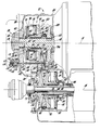
- a motor vehicle transmission which incorporates one embodiment of a variable-ratio drive mechanism, generally designated 12, in accordance with the present invention.
- the transmission 10 has an input axis 14 which is substantially coaxial with an engine crankshaft, not shown, and also has an output axis 16 which is substantially coaxial with a pair of vehicle drive axles, not shown.
- An input shaft 18 is rotatably supported in bearings 20 and 22 disposed in transmission housings 24 and 26, respectively.
- the input shaft 18 is coaxial with the input axis 14, and has drivingly connected thereto a pair of pulley halves (discs) 28 and 30.
- the pulley half 28 is maintained stationary in an axial (longitudinal) direction relative to the input shaft 18, whereas the pulley half 30 is permitted to move axially (longitudinally) relative to the input shaft 18.
- Both pulley halves 28 and 30 rotate in unison with the input shaft 18, which is adapted to be driven either directly by the engine crankshaft or through an intervening friction clutch or fluid drive mechanism, not shown. Any of the well-known friction-clutch mechanisms, either manually or automatically engaged, or fluid drive mechanisms can be utilized.
- the axially movable pulley half 30 is drivingly connected to a ball spline 32, and has formed integrally therewith an inner hub 34 and an outer hub 36.
- the inner hub 34 carries a seal member 38 which sealingly engages an inner cylinder portion 40 formed integrally with a cylinder housing 42.
- the cylinder housing 42 also includes an outer cylinder portion 44 which is sealingly engaged by a lip seal 46 secured in a longitudinally movable piston member 48.
- the piston member 48 has a hollow cylindrical portion 50 which abuts the pulley half 30.
- An annular dividing member 52 has fixed thereto a pair of lip seals 54 and 56 which sealingly engage the cylindrical portion 50 and outer hub 36 respectively.
- the dividing member 52 abuts the outer cylinder portion 44, and is secured on the input shaft 18 in a manner preventing longitudinal movement thereon.
- the piston member 48 and the cylinder housing 42 cooperate to form a pressure chamber 58
- the dividing member 52 and the axially movable pulley half 30 cooperate to form a pressure chamber 60.
- the piston member 48 and the axially movable pulley half 30 are operable to move in unison longitudinally relative to the input shaft 18 in response to fluid pressure within the chambers 58 and 60.
- These chambers 58 and 60 are interconnected by means of a fluid passage 62 and the space between the inner cylinder portion 40 and the hollow cylindrical portion 50.
- the pulley halves 28 and 30 cooperate to form a drive pulley (sheave) generally designated 64, which is operatively connected to drive belt 66.
- the drive belt 66 is also connected to a driven pulley (sheave) generally designated 68, having belt-receiving discs comprising an axially (longitudinally) stationary pulley half 70 and an axially (longitudinally) movable pulley half 72.
- the axially stationary pulley half 70 is drivingly connected directly to a sleeve shaft '74
- the axially movable pulley half 72 is drivingly connected by way of a ball spline 76 to the sleeve shaft 74.
- the sleeve shaft 74 is adapted to be connected to a planetary gearing mechansim (not shown) such as that disclosed in our European Patent application 81302025.2.
- variable-ratio pulley mechanism which can incorporate the drive mechanism described herein.
- the axially movable pulley half 72 has secured thereto a housing 78 which is sealingly engaged by a lip seal 80 disposed in a stationary wall 82.
- the stationary wall 82 cooperates with the housing 78 and the axially movable pulley half 72 to form a pressure chamber 84.
- the radially inner portion of the pressure chamber 84 is sealed by a lip seal 86 which is disposed in a hub 88 on the axially movable pulley half 72 and sealingly engages a housing 90 secured to the sleeve shaft 74.
- a compression spring 92 is disposed in the pressure chamber 84, and is operatively connected between the axially movable pulley half 72 and the stationary wall member 82. The spring 92, assisted by fluid pressure within the chamber 84,urges the pulley half 72 leftwardly towards the maximum underdrive ratio shown.
- the input shaft.18 is also drivingly connected to a positive-displacement pump, generally designated 94.
- the pump 94 may be of any of the well-known designs for transmission control pumps, and is preferably of the variable-displacement type, such that maxium efficiency can be obtained.
- such.fluid pumps provide positive fluid pressure for transmission control systems, wherein the fluid pressure can be controlled to be proportional to engine torque and engine speed or vehicle speed.
- the pump 94 is connected to a pressure control system of conventional design, not shown, which in turn directs system pressure to a passage 96 and a passage 98.
- the control system in conventional fashion, is effective to provide a system pressure proportional to the vehicle or engine operating parameters.
- the passage 98 is connected between the stationary wall 82 and the housing 90 to the chamber 84.
- the passage 96 is in fluid communication with a valve mechanism, generally desingated 100.
- the valve mechanism 100 includes a valve spool 102 having a pair of equal-diameter lands 104 and 106 slidably disposed in a valve bore 108.
- the valve spool 102 is urged to the right by a spring member 110 into abutment with an actuator rod 112,.which rod is reciprocable on an axis that is parallel to the input axis 14 representing the axis of rotation of the drive pulley 64.
- the valve land 106 registers with a fluid port 114 connected to a passage 116, which in turn is connected to the passage 62.
- the passage 62 is in fluid communication with the pressure chambers, 58 and 60.
- the space containing the spring member 110, and therefore the left-hand side of the land 106, is connected to an exhaust port 118, and the space between the valve lands 106 and 104 is in fluid communication with the system pressure in the passage 96.
- the valve land 106 is designed to provide either line-to-line sealing of the port port 114 or slight underlapping of the port: it is preferable that.slight underlapping be achieved.
- the pressure in the port 114 and therefore in the passages 116 and 62 is less than system pressure when the valve spool 102 is in the position shown. If the valve spool 102 is moved to the left, the pressure in the port 114 will be equal to system pressure, whereas if the valve spool 102 is moved to the right the pressure in the port 114 will be equal to exhaust pressure. Thus the pressure in the chambers 58 and 60 can be controlled between full system pressure and exhaust pressure by the movement of the valve spool 102. The pressure within the pressure chamber 84 of the pulley 68, however, is always maintained equal to system pressure, and thus establishes a primary tension force in the drive belt 66.
- the pulley half 30 will move to the right towards the phantom position shown at 120, which is the maximum overdrive position for the variable-ratio drive mechanism 12.
- Rotary movement of the pulley half 30 is transmitted by the drive belt 66 to the pulley half 72. If the force on the pulley half 62 is greater than the force on the pulley half 30, the pulley half 72 will move towards the position shown, and the drive belt 66 will cause the pulley half 30 to respond to such movement by movement leftwardly.
- the pressure chambers operable on the pulley half 30 must be greater in area than the pressure chamber operable on the pulley half 72.
- the pulley half 30 utilizes a double- chamber arrangement such that the wall of the pulley half 30 is effectively a pressure piston.
- a single-area chamber could be utilised if the space were available.
- the actuator rod 112 is slidably disposed in apertures 122 and 124 formed in the housing 26 and a block 125 respectively.
- a shoulder 126 is formed on the actuator rod 112, and a spring member,128 is compressed between the shoulder 126 and the housing 24. This spring member 128 biases the actuator rod 112.to the left, and has a force stored therein which is greater than the force in the spring member 110.
- the actuator rod 112 has secured thereto a pin 130 which forms a pivot for a control lever 132.
- the drive belt.66 interconnecting the drive and driven pulleys 64 and 68 encompasses a space which is between the pulleys under all conditions, and the control lever 132 is located in this space, substantially on a line intersecting the input and output axes of rotation 14 and 16 of the pulleys.
- the lever 132 has one end 134 in abutment with a conical surface 136 of the pulley half 30; and its other end 138 in abutment with a control rod 140 which is the output member for a control mechanism 142.
- the pin 130 engages the opposite side of the lever 132 from the side which is in abutment with the pulley half 30 and with the control rod 140.
- the control mechanism 142 is conventional linear actuator, such as a stepper motor or a variable force solenoid, which includes an output member that moves linearly in response to an input control signal.
- the control mechanism 142 could alternatively compirse a mechanical device effective to produce a linear actuator output.
- control signal may be proportional to any of the various or engine operting parameters such as engine torque, operator demand, vehicle speed and engine speed.
- variable drive ratio pulley mechanism 12 is shown in the maximum under dr i ve ratio. That is, speed is reduced as drive torque is transmitted from the pulley 64 to the pulley 68 by means of the drive belt.66, and torque is increased. If the operating conditions of the vehicle are such that the drive ratio should be changed to provide a higher output speed relative to input speed, the control rod 140 will move leftwardly towards the phantom position 144 shown for the lever 132.
- the spring member 128, which has a higher force stored therein than the spring member 110, will thereby move the actuator rod 112, and consequently the valve.spool 102, leftwardly such that system pressure is directed through the passage 114, the passage 116 and the passage 62 to the pressure chambers 58 and 60.
- This pressure in the chambers 58 and 60 will result in rightward movement of the piston member 4.8 and the pulley.half 30, such that the drive belt 66 will move outwardly on the conical surfaces of the drive pulley 64, thereby forcing the drive belt 66 inwardly on the conical surfaces of the driven pulley 68.
- the control rod 140 will be moved to the right, towards the lever position shown in solid lines, such that the lever 132 will pivot about its end 134 to the position 146 shown in phantom. This pivoting of the lever 132 will result in movement of the actuator rod 112 to the right, such that the spring member 110 will be able to move the valve spool 102 to the right.
- Such movement of the valve spool will provide an exhaust connection for the passage 114 such that the fluid pressure in the chambers 58 and 60 will be connected to exhaust.
Landscapes
- Engineering & Computer Science (AREA)
- General Engineering & Computer Science (AREA)
- Mechanical Engineering (AREA)
- Transmissions By Endless Flexible Members (AREA)
- Control Of Transmission Device (AREA)
Applications Claiming Priority (2)
| Application Number | Priority Date | Filing Date | Title |
|---|---|---|---|
| US204955 | 1980-11-07 | ||
| US06/204,955 US4403974A (en) | 1980-11-07 | 1980-11-07 | Position control mechanism for a variable drive ratio pulley system |
Publications (3)
| Publication Number | Publication Date |
|---|---|
| EP0051918A2 true EP0051918A2 (de) | 1982-05-19 |
| EP0051918A3 EP0051918A3 (en) | 1983-05-11 |
| EP0051918B1 EP0051918B1 (de) | 1986-02-26 |
Family
ID=22760162
Family Applications (1)
| Application Number | Title | Priority Date | Filing Date |
|---|---|---|---|
| EP81304427A Expired EP0051918B1 (de) | 1980-11-07 | 1981-09-25 | Getriebe mit veränderbarer Übersetzung |
Country Status (5)
| Country | Link |
|---|---|
| US (1) | US4403974A (de) |
| EP (1) | EP0051918B1 (de) |
| JP (1) | JPS57107459A (de) |
| CA (1) | CA1151444A (de) |
| DE (1) | DE3173890D1 (de) |
Cited By (4)
| Publication number | Priority date | Publication date | Assignee | Title |
|---|---|---|---|---|
| GB2129838A (en) * | 1982-11-10 | 1984-05-23 | Domar Sa | Variable speed drive |
| DE3307329A1 (de) * | 1983-03-02 | 1984-09-06 | Audi Nsu Auto Union Ag, 7107 Neckarsulm | Hydraulische steuervorrichtung |
| EP0168929A1 (de) * | 1984-06-18 | 1986-01-22 | General Motors Corporation | Druckkompensierende Anordnung |
| US4680991A (en) * | 1984-01-30 | 1987-07-21 | Fuji Jukogyo Kabushiki Kaisha | System for controlling the transmission ratio in an infinitely variable transmission |
Families Citing this family (16)
| Publication number | Priority date | Publication date | Assignee | Title |
|---|---|---|---|---|
| US4483687A (en) * | 1980-12-12 | 1984-11-20 | Ab Volvo | Vehicle gearbox with continuously variable gear ratio |
| IT1135352B (it) * | 1981-02-06 | 1986-08-20 | Alfa Romeo Spa | Cambio di velocita' automatico continuo per autoveicoli |
| JPS57161346A (en) * | 1981-03-28 | 1982-10-04 | Nissan Motor Co Ltd | Speed change control method for v-belt stepless speed change gear |
| US4494943A (en) * | 1981-09-08 | 1985-01-22 | Nippondenso Co., Ltd. | Power transmission device for vehicles |
| US4509125A (en) * | 1982-08-06 | 1985-04-02 | General Motors Corporation | Continuously variable transmission ratio control system |
| JPS60222647A (ja) * | 1984-04-18 | 1985-11-07 | Toyota Motor Corp | 自動車用無段変速機の制御装置 |
| JPH06100265B2 (ja) * | 1984-07-16 | 1994-12-12 | 本田技研工業株式会社 | 自動無段変速機における可動プ−リの側圧制御装置 |
| FI75035C (fi) * | 1986-06-17 | 1988-04-11 | Variped Oy | Automatisk reglervaexel foer fordon. |
| US4767384A (en) * | 1987-04-06 | 1988-08-30 | Ford Motor Company | Fluid pressure amplifier for an infinitely variable drive |
| JPS63195150U (de) * | 1987-06-05 | 1988-12-15 | ||
| US4909776A (en) * | 1987-08-28 | 1990-03-20 | Aisin Aw Co., Ltd. | Continuously variable transmission |
| JP2656501B2 (ja) * | 1987-08-28 | 1997-09-24 | アイシン・エィ・ダブリュ株式会社 | ベルト式無段変速装置 |
| US5795256A (en) * | 1996-01-22 | 1998-08-18 | Honda Giken Kogyo Kabushiki Kaisha | Jig apparatus for assembling belt onto variator |
| JP2004156658A (ja) * | 2002-11-05 | 2004-06-03 | Yamaha Motor Co Ltd | エンジン |
| US7351187B2 (en) * | 2005-10-22 | 2008-04-01 | Joseph Seliber | Resistance and power monitoring device and system for exercise equipment |
| US8459431B2 (en) * | 2009-07-27 | 2013-06-11 | Borgwarner Inc. | Housing member for clutch mechanism |
Family Cites Families (17)
| Publication number | Priority date | Publication date | Assignee | Title |
|---|---|---|---|---|
| US2087642A (en) * | 1936-01-21 | 1937-07-20 | Forsberg Fredrick | Pulley transmission system |
| FR1293574A (fr) * | 1961-04-04 | 1962-05-18 | Cazeneuve Sa | Variateur de vitesse à courroie trapézoïdale passant sur des poulies à flasques coniques de diamètre progressivement variable, à rapport de transmission asservi à la position de l'organe de commande |
| DE1081733B (de) * | 1958-07-19 | 1960-05-12 | Reimers Getriebe K G | Steuereinrichtung an stufenlos verstellbaren Getrieben mit zwischen axial verschiebbaren Kegelscheibenpaaren laufenden Zugmittelstraengen und hydraulischer Verstelleinrichtung |
| DE1210648B (de) * | 1958-12-12 | 1966-02-10 | Reimers Getriebe K G | Stufenlos verstellbares Kegelscheibengetriebe mit wenigstens einer auf eine der axial verschiebbaren Kegelscheiben einwirkenden mechanischen Anpresseinrichtung zur Erzeugung von dreh-moment- und uebersetzungsabhaengigen Anpress-kraeften |
| DE1141502B (de) * | 1959-03-06 | 1962-12-20 | Reimers Getriebe K G | Hydraulisch gesteuertes Kegelscheibenumschlingungsgetriebe |
| ES256110A1 (es) * | 1959-03-21 | 1960-08-16 | Doorne S Automobielfabriek N V | Un vehiculo de motor |
| DE1254981C2 (de) * | 1960-08-04 | 1973-03-01 | Piv Antrieb Reimers Kg Werner | Steuereinrichtung fuer das stufenlos verstellbare Wechselgetriebe eines Antriebsaggregates, insbesondere fuer Kraftfahrzeuge |
| US3110189A (en) * | 1961-01-25 | 1963-11-12 | Reimers Getriebe Kg | Infinitely variable pulley gear |
| GB1115362A (en) * | 1964-10-14 | 1968-05-29 | Hartridge Ltd Leslie | Improvements in and relating to variable speed drives |
| DE1455865A1 (de) * | 1965-03-10 | 1969-06-19 | Piv Antrieb Reimers Kg Werner | Vorrichtung zur Veraenderung der Verstellgeschwindigkeit zur Verwendung in Fahrzeugen bestimmter,hydraulisch gesteuerter,stufenlos verstellbarer Getriebe |
| US3451283A (en) * | 1967-08-16 | 1969-06-24 | Reimers Getriebe Ag | Infinitely variable cone pulley transmission |
| DE1816949B1 (de) * | 1968-12-24 | 1970-05-27 | Piv Antrieb Reimers Kg Werner | Kegelscheiben-Umschlingungsgetriebe |
| US3699827A (en) * | 1971-07-09 | 1972-10-24 | Hilmar Vogel | Axial actuator and force control for rotary members, especially variable speed drives |
| DE2301776B2 (de) * | 1973-01-15 | 1976-12-02 | P.I.V. Antrieb Werner Reimers Kg, 6380 Bad Homburg | Steuereinrichtung fuer einen aus einer brennkraftmaschine und motor und einem von dieser angetriebenen stufenlos einstellbarem zugorgangetriebe bestehenden fahrantrieb |
| DE2329364A1 (de) * | 1973-06-08 | 1975-01-02 | Bosch Gmbh Robert | Automatisches getriebe fuer kraftfahrzeuge |
| NL168038B (nl) * | 1978-05-03 | 1981-09-16 | Doornes Transmissie Bv | Inrichting voor het regelen van de overbrengings- verhouding van een traploos variabele transmissie van een motorvoertuig. |
| NL7811192A (nl) * | 1978-11-13 | 1980-05-16 | Doornes Transmissie Bv | Werkwijze en inrichting voor het regelen van een trap- loos variabele transmissie van een motorvoertuig. |
-
1980
- 1980-11-07 US US06/204,955 patent/US4403974A/en not_active Expired - Lifetime
-
1981
- 1981-09-14 CA CA000385863A patent/CA1151444A/en not_active Expired
- 1981-09-25 DE DE8181304427T patent/DE3173890D1/de not_active Expired
- 1981-09-25 EP EP81304427A patent/EP0051918B1/de not_active Expired
- 1981-11-07 JP JP56177845A patent/JPS57107459A/ja active Granted
Cited By (4)
| Publication number | Priority date | Publication date | Assignee | Title |
|---|---|---|---|---|
| GB2129838A (en) * | 1982-11-10 | 1984-05-23 | Domar Sa | Variable speed drive |
| DE3307329A1 (de) * | 1983-03-02 | 1984-09-06 | Audi Nsu Auto Union Ag, 7107 Neckarsulm | Hydraulische steuervorrichtung |
| US4680991A (en) * | 1984-01-30 | 1987-07-21 | Fuji Jukogyo Kabushiki Kaisha | System for controlling the transmission ratio in an infinitely variable transmission |
| EP0168929A1 (de) * | 1984-06-18 | 1986-01-22 | General Motors Corporation | Druckkompensierende Anordnung |
Also Published As
| Publication number | Publication date |
|---|---|
| EP0051918A3 (en) | 1983-05-11 |
| EP0051918B1 (de) | 1986-02-26 |
| JPS57107459A (en) | 1982-07-03 |
| JPS6349104B2 (de) | 1988-10-03 |
| US4403974A (en) | 1983-09-13 |
| DE3173890D1 (en) | 1986-04-03 |
| CA1151444A (en) | 1983-08-09 |
Similar Documents
| Publication | Publication Date | Title |
|---|---|---|
| EP0051918B1 (de) | Getriebe mit veränderbarer Übersetzung | |
| US5711730A (en) | Torque monitoring apparatus | |
| US4717368A (en) | Stepless belt transmission | |
| US4519790A (en) | Hydraulic control system for continuously variable V-belt transmission | |
| US3943715A (en) | Servo mechanism | |
| GB2043808A (en) | Infinitely variable conepulley belt-type transmission | |
| US6287227B1 (en) | Hydraulic control for a continuously variable transmission | |
| CA1293908C (en) | Control device for a continuously variable transmission for motor vehicles | |
| US3842694A (en) | Hydromechanical transmission and control | |
| US3949627A (en) | Fluid pressure control system for automatic fluid transmissions | |
| EP0061736A2 (de) | Stufenlos regelbares Riemengetriebe mit hydrodynamischem Drehmomentwandler mit Überbrückungskupplung | |
| US5407394A (en) | Guide for an adjustable pulley in a continuously variable transmission | |
| US5046592A (en) | Servo shift control for a forward/reverse mechanism | |
| GB2027854A (en) | Hydrostatic transmission control | |
| US4270415A (en) | Traction-drive transmission with hydraulic control | |
| US4111074A (en) | Hydraulic control for hydromechanical transmission | |
| US2916927A (en) | Variable speed belt drive | |
| US4601368A (en) | Infinitely variable ratio transmission | |
| CA2097202C (en) | Conduit valve providing wide neutral in a hydrostatic transmission | |
| US4131056A (en) | Pilot controlled variable displacement fluid motor | |
| US4608031A (en) | Control system for a continuously variable transmission | |
| EP0534971A1 (de) | Steuerungssystem für ein stufenloses kegelscheibengetriebe | |
| US4747809A (en) | Hydraulic control for a continuously variable transmission | |
| CA2114392C (en) | Bevel gear load balance in a hydrostatic transmission | |
| US4184330A (en) | Hydrodynamic reversing transmission |
Legal Events
| Date | Code | Title | Description |
|---|---|---|---|
| PUAI | Public reference made under article 153(3) epc to a published international application that has entered the european phase |
Free format text: ORIGINAL CODE: 0009012 |
|
| AK | Designated contracting states |
Designated state(s): DE FR GB IT NL |
|
| PUAL | Search report despatched |
Free format text: ORIGINAL CODE: 0009013 |
|
| AK | Designated contracting states |
Designated state(s): DE FR GB IT NL |
|
| 17P | Request for examination filed |
Effective date: 19830613 |
|
| GRAA | (expected) grant |
Free format text: ORIGINAL CODE: 0009210 |
|
| ITF | It: translation for a ep patent filed | ||
| AK | Designated contracting states |
Designated state(s): DE FR GB IT NL |
|
| REF | Corresponds to: |
Ref document number: 3173890 Country of ref document: DE Date of ref document: 19860403 |
|
| ET | Fr: translation filed | ||
| PLBE | No opposition filed within time limit |
Free format text: ORIGINAL CODE: 0009261 |
|
| STAA | Information on the status of an ep patent application or granted ep patent |
Free format text: STATUS: NO OPPOSITION FILED WITHIN TIME LIMIT |
|
| 26N | No opposition filed | ||
| PGFP | Annual fee paid to national office [announced via postgrant information from national office to epo] |
Ref country code: GB Payment date: 19900813 Year of fee payment: 10 |
|
| PGFP | Annual fee paid to national office [announced via postgrant information from national office to epo] |
Ref country code: FR Payment date: 19900927 Year of fee payment: 10 |
|
| PGFP | Annual fee paid to national office [announced via postgrant information from national office to epo] |
Ref country code: NL Payment date: 19900930 Year of fee payment: 10 |
|
| PGFP | Annual fee paid to national office [announced via postgrant information from national office to epo] |
Ref country code: DE Payment date: 19901114 Year of fee payment: 10 |
|
| PG25 | Lapsed in a contracting state [announced via postgrant information from national office to epo] |
Ref country code: GB Effective date: 19910925 |
|
| PG25 | Lapsed in a contracting state [announced via postgrant information from national office to epo] |
Ref country code: NL Effective date: 19920401 |
|
| NLV4 | Nl: lapsed or anulled due to non-payment of the annual fee | ||
| GBPC | Gb: european patent ceased through non-payment of renewal fee | ||
| PG25 | Lapsed in a contracting state [announced via postgrant information from national office to epo] |
Ref country code: FR Effective date: 19920529 |
|
| PG25 | Lapsed in a contracting state [announced via postgrant information from national office to epo] |
Ref country code: DE Effective date: 19920602 |
|
| REG | Reference to a national code |
Ref country code: FR Ref legal event code: ST |