EP0051547A1 - Pneumatically operated threading device for a two-for-one twisting spindle - Google Patents
Pneumatically operated threading device for a two-for-one twisting spindle Download PDFInfo
- Publication number
- EP0051547A1 EP0051547A1 EP81420147A EP81420147A EP0051547A1 EP 0051547 A1 EP0051547 A1 EP 0051547A1 EP 81420147 A EP81420147 A EP 81420147A EP 81420147 A EP81420147 A EP 81420147A EP 0051547 A1 EP0051547 A1 EP 0051547A1
- Authority
- EP
- European Patent Office
- Prior art keywords
- capsule
- piston
- bore
- wire
- sleeve
- Prior art date
- Legal status (The legal status is an assumption and is not a legal conclusion. Google has not performed a legal analysis and makes no representation as to the accuracy of the status listed.)
- Ceased
Links
Images

Classifications
-
- D—TEXTILES; PAPER
- D01—NATURAL OR MAN-MADE THREADS OR FIBRES; SPINNING
- D01H—SPINNING OR TWISTING
- D01H15/00—Piecing arrangements ; Automatic end-finding, e.g. by suction and reverse package rotation; Devices for temporarily storing yarn during piecing
- D01H15/007—Piecing arrangements ; Automatic end-finding, e.g. by suction and reverse package rotation; Devices for temporarily storing yarn during piecing for two-for-one twisting machines
-
- D—TEXTILES; PAPER
- D01—NATURAL OR MAN-MADE THREADS OR FIBRES; SPINNING
- D01H—SPINNING OR TWISTING
- D01H13/00—Other common constructional features, details or accessories
- D01H13/10—Tension devices
- D01H13/104—Regulating tension by devices acting on running yarn and not associated with supply or take-up devices
- D01H13/106—Regulating tension by devices acting on running yarn and not associated with supply or take-up devices for double-twist spindle
Definitions
- the present invention relates to improvements made to pneumatic threading systems for the wire in the bore of a double twist spindle, this bore being provided with a wire brake.
- the pneumatic threading device has a very small number of parts so that its construction is very economical.
- the compressed air used by the device according to the invention is introduced into this spindle by its usual bore through which the thread is twisted.
- the spindle is produced by two tubes joined by a connecting sleeve in which are arranged means for laterally moving the wire brake relative to said bore when the pressurized air is introduced into the latter.
- the wire brake which is produced in the form of a usual telescopic capsule, then releases the bore and allows a wire placed at the head of the spindle to be freely introduced into its bore.
- the introduction of the wire is carried out by means of a gun such as that described in the aforementioned French patent 77 22839 of the Applicant.
- the thread 1a of the tube 1 stops at some distance from its end to determine a smooth cylindrical seat 1b capable of cooperating with an O-ring 4 of the sleeve 3.
- a ring 5 cooperates with the thread 1a of the tube 1 to determine the relative position of the latter relative to the sleeve 3.
- the lower tube 2 has a thread 2a which stops before the end of the tube in order to determine a smooth cylindrical surface 2b.
- the sleeve also includes a seal 4 'for reasons which will be better explained below. Said end is associated with a stepped end-piece 6 pierced through and through and the part with a smaller diameter penetrates into the bore 2c of the tube 2. Between the shoulder 6a of the end-piece 6 and the annular end of the tube 2 a compression spring 7 is placed.
- the larger diameter part 6b of the end piece 6 is slidably mounted just in the bore 3a of the sleeve 3.
- the outlet upwards from the central hole 6c of the end piece 6 is chamfered as is the outlet of the bore lc of the tube 1.
- the outlets considered are connected by the usual wire brake which is produced by means of a capsule 8 formed by two telescopic tubular elements referenced 8a and 8b and the ends of which are each closed by a spherical cap.
- a compression spring 9 is placed between the two elements of the capsule 8 in order to separate them from one another.
- the adjustment of the penetration of the tubes 1 and 2 in the sleeve 3 is intended to allow suitable crushing of the spring 9 by penetration of the element 8b inside that 8a.
- the sleeve 3 is provided with a transverse groove 10 which passes through its central bore 3a to reach a cylindrical housing 11 opening outwards.
- a piston 12 with a cylindrical head comprising a flat tail 13 which slides with clearance in the groove 10.
- a plug 14 closes the outlet towards the outside of the housing 11.
- the bore 3a of the sleeve 3 communicates it with said housing.
- the latter is roughly rectangular and it comprises two intersecting circular openings one 13a with a diameter greater than that of the other 13b.
- the outside diameter of the element 8b of the capsule 8 has a diameter greater than the width of the opening 13c making the two openings 13a and 13b communicate for reasons which will be better explained below.
- the piston 12 Prior to placing the capsule 8 in the sleeve 3, the piston 12 is placed in the position shown in fig. l and 2 so that the capsule 8 can be engaged in the hole 13a of the tail 13 of this piston.
- seals 4, 4 ′ prevent any air from escaping between the sleeve and the tubes 1 and 2 respectively.
- a pneumatic threading device has thus been produced in a double twist spindle which is particularly effective while being very modest in cost.
Abstract
Il est disposé à l'intérieur d'un manchon (3) réunissant deux tubes (1, 2) propres à constituer la partie centrale d'une broche à double torsion. Une capsule (8) traversant la queue plate (13) d'un piston (12) est disposée à l'intérieur du manchon, ses extrémités prenant appui contre les débouchés de l'alésage (1c) du tube (1) et contre celui du trou central (6c) d'un embout monté à l'extrémité inférieure du tube (2). Lorsqu'on envoie de l'air comprimé dans l'alésage (1c) on provoque le retrait du piston (12) qui entraîne un décalage latéral de la capsule permettant ainsi le passage du fil tout le long de l'alésage de la broche.It is arranged inside a sleeve (3) joining two tubes (1, 2) suitable for constituting the central part of a double twist spindle. A capsule (8) passing through the flat tail (13) of a piston (12) is disposed inside the sleeve, its ends bearing against the outlets of the bore (1c) of the tube (1) and against that the central hole (6c) of a nozzle mounted at the lower end of the tube (2). When compressed air is sent into the bore (1c), the piston (12) is withdrawn, which causes a lateral offset of the capsule, thus allowing the passage of the wire all along the bore of the spindle.
Description
La présente invention est relative à des perfectionnements apportés aux systèmes d'enfilage pneumatique du fil dans l'alésage d'une broche à double torsion, cet alésage étant pourvu d'un frein de fil.The present invention relates to improvements made to pneumatic threading systems for the wire in the bore of a double twist spindle, this bore being provided with a wire brake.
On a décrit dans le brevet 77 22839 au nom de la présente Demanderesse un dispositif du genre en question qui donne tout à fait satisfaction sur le plan technique. Malheureusement sa réalisation est complexe et il comprend un nombre important de pièces de sorte que son prix de revient est élevé.There has been described in patent 77 22839 in the name of the present Applicant a device of the kind in question which is entirely satisfactory on the technical level. Unfortunately its realization is complex and it includes a large number of parts so that its cost price is high.
Les perfectionnements qui font l'objet de la présente invention visent à remédier aux inconvénients du brevet précité.The improvements which are the subject of the present invention aim to remedy the drawbacks of the aforementioned patent.
Le dispositif d'enfilage pneumatique suivant l'invention comporte un très faible nombre de pièces si bien que sa construction est très économique. Au lieu de prévoir deux alésages côte à côte dans la broche, L'air comprimé utilisé par le dispositif suivant l'invention est introduit dans cette broche par son alésage usuel par lequel passe.le fil à retordre. La broche est réalisée grâce à deux tubes réunis par un manchon de liaison dans lequel sont disposés des moyens de déplacer latéralement le frein de fil par rapport audit alésage quand l'air sous pression est introduit dans ce dernier. Le frein de fil, qui est réalisé sous la forme d'une capsule télescopique usuelle, dégage alors l'alésage et permet à un fil placé en tête de la broche d'être introduit librement dans son alésage.The pneumatic threading device according to the invention has a very small number of parts so that its construction is very economical. Instead of providing two bores side by side in the spindle, the compressed air used by the device according to the invention is introduced into this spindle by its usual bore through which the thread is twisted. The spindle is produced by two tubes joined by a connecting sleeve in which are arranged means for laterally moving the wire brake relative to said bore when the pressurized air is introduced into the latter. The wire brake, which is produced in the form of a usual telescopic capsule, then releases the bore and allows a wire placed at the head of the spindle to be freely introduced into its bore.
L'introduction du fil s'effectue au moyen d'un pistolet tel que celui décrit dans le brevet français 77 22839 précité de la Demanderesse.The introduction of the wire is carried out by means of a gun such as that described in the aforementioned French patent 77 22839 of the Applicant.
Le dessin annexé, donné à titre d'exemple, permettra de mieux comprendre l'invention les caractéristiques qu'elle présente et les avantages qu'elle est susceptible de procurer :
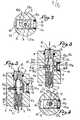
- Fig. 1 est une coupe longitudinale d'une broche à double torsion pourvue d'un dispositif d'enfilage pneumatique établi conformément à l'invention.
- Fig. 2 en est une coupe suivant II-II (fig. 1).
- Fig. 3 est une vue partielle correspondant à fig. l mais montrant le frein de fil à sa position effacée.
- Fig. 4 en est une coupe suivant IV-IV (fig. 3).
- Fig. 5 est une vue semblable à celle de fig. 3 mais montrant le fil coincé par le frein de fil après qu'il ait été engagé dans l'alésage de la broche.
- Fig. 1 is a longitudinal section of a double twist spindle provided with a pneumatic threading device established in accordance with the invention.
- Fig. 2 is a section along II-II (fig. 1).
- Fig. 3 is a partial view corresponding to FIG. l but showing the wire brake in its cleared position.
- Fig. 4 is a section on IV-IV (fig. 3).
- Fig. 5 is a view similar to that of FIG. 3 but showing the wire jammed by the wire brake after it has been engaged in the spindle bore.
On a illustré en fig. 1 la partie centrale d'une broche à double torsion réalisée au moyen de deux tubes 1, 2 dont les extrémités sont filetées de manière à être réunies par l'intermédiaire d'un manchon 3.Illustrated in fig. 1 the central part of a double twist spindle produced by means of two
On observe que le filetage la du tube 1 s'arrête à quelque distance de son extrémité pour déterminer une portée cylindrique lisse lb propre à coopérer avec un joint torique 4 du manchon 3. Une bague 5 coopère avec le filetage la du tube 1 pour déterminer la position relative de ce dernier par rapport au manchon 3.It is observed that the
De même manière le tube inférieur 2 comporte un filetage 2a qui s'arrête avant l'extrémité du tube en vue de déterminer une portée cylindrique lisse 2b. A ce niveau le manchon comprend également un joint d'étanchéité 4' pour des raisons qu'on expliquera mieux plus loin. Ladite extrémité est associée à un embout étagé 6 percé de part en part et dont la partie à plus faible diamètre pénètre dans l'alésage 2c du tube 2. Entre l'épaulement 6a de l'embout 6 et l'extrémité annulaire du tube 2 est placé un ressort de compression 7.Similarly, the
La partie à plus grand diamètre 6b de l'embout 6 est montée coulissante juste dans l'alésage 3a du manchon 3. Le débouché vers le haut du trou central 6c de l'embout 6 est chanfreiné de même que le débouché de l'alésage lc du tube 1. Les débouchés considérés sont reliés par le frein de fil usuel qui est réalisé au moyen d'une capsule 8 formée de deux éléments tubulaires télescopiques référencés 8a et 8b et dont les extrémités sont chacune fermées par une calotte sphérique. Un ressort de compression 9 est placé entre les deux éléments de la capsule 8 en vue de les écarter l'un de l'autre. Le réglage de la pénétration des tubes 1 et 2 dans le manchon 3 est destiné à permettre un écrasement convenable du ressort 9 par pénétration de l'élément 8b à l'intérieur de celui 8a.The
Le manchon 3 est pourvu d'une saignée transversale 10 qui traverse son alésage central 3a pour parvenir dans un logement cylindrique 11 débouchant vers l'extérieur. Dans ce logement est engagé un piston 12 à tête cylindrique comportant une queue plate 13 qui s'enfile avec jeu dans la saignée 10. Un bouchon 14 ferme le débouché vers l'extérieur du logement 11. Ainsi l'alésage 3a du manchon 3 communique-t-il avec ledit logement.The
On a illustré en fig. 2 la forme particulière de la queue 13 du piston 12. Celle-ci est en gros rectangulaire et elle comporte deux ouvertures circulaires sécantes l'une 13a d'un diamètre supérieur à celui de l'autre 13b. On notera que le diamètre extérieur de l'élément 8b de la capsule 8 présente un diamètre supérieur à la largeur de la lumière 13c faisant communiquer les deux ouvertures 13a et 13b pour des raisons qu'on expliquera mieux plus loin.Illustrated in fig. 2 the particular shape of the
Préalablement à la mise en place de la capsule 8 dans le manchon 3 on place le piston 12 dans la position représentée en fig. l et 2 de manière que la capsule 8 puisse être engagée dans le trou 13a de la queue 13 de ce piston.Prior to placing the
Le fonctionnement découle des explications qui précèdent : Lorsque le dispositif d'enfilage automatique ne fonctionne pas le piston 12 se trouve dans la position illustrée en fig. 1 et 2 c'est-à-dire que sa tête est en appui contre le fond du logement 11 tandis que les calottes sphériques des deux éléments 8a, 8b de la capsule 8 sont en appui contre les débouchés respectivement de l'alésage lc du tube 1 et du trou central 6c de l'embout 6.The operation follows from the above explanations: When the automatic threading device does not work, the
Si l'on désire introduire un fil traversant les deux tubes 1 et 2 on présente au débouché supérieur de l'alésage lc du . tube 1 un pistolet tel que celui décrit dans la demande de brevet 77 23839 de la présente Demanderesse mais qui ne comporterait qu'un seul trou d'amenée d'air au lieu de deux. L'air arrivant sous pression dans l'alésage lc du tube 1 pénètre dans l'espace entourant la capsule 8 et vient sous la tête du piston 12 pour provoquer son déplacement vers la droite jusqu'à ce que la tête soit en appui contre le bouchon 14 (fig. 3). Ce déplacement du piston entraîne celui latéral de la capsule 8 dont les deux éléments s'interpénètrent élastiquement à l'encontre de la réaction du ressort 9 de telle sorte que les débouchés en vis-à-vis des tubes 1 et 2 sont libres. On observe que l'entraînement de la capsule 8 par la queue 13 du piston 12 s'effectue par appui des deux bords de la lumière 13c contre la périphérie de la capsule 8. Par suite de l'évasement des débouchés de l'alésage lc et du trou 6c de l'embout 6, on provoque une contraction du ressort 9.If one wishes to introduce a wire passing through the two
En introduisant ensuite un fil 15 à l'extrémité libre de l'alésage lc, il est entraîné par l'air comprimé et passe dans le trou 6c de l'embout 6, puis dans celui 2c du tube 2 pour ressortir à l'endroit désiré de la broche à double torsion en ayant préalablement traversé le petit trou 13a de la queue 13 (fig. 4) lequel se trouve en gros dans l'axe géométrique des deux alésages lc, 2c.Then introducing a
La description ci-dessus a été faite comme si l'embout 6 était solidaire de l'extrémité intérieure du tube 2. En réalité et sans que cela soit une obligation l'on préfère utiliser l'embout 6 et le ressort 7 de telle sorte qu'une fois l'air arrivé dans la chambre formée au centre de l'alésage 3a du manchon 3 il provoque une légère descente de l'embout 6 qui favorise le déplacement latéral de la capsule 8 par l'intermédiaire de la queue 13 du piston 12.The above description has been made as if the
Bien entendu les joints 4, 4' évitent toute sortie d'air entre le manchon et respectivement les tubes 1 et 2.Of course the
Un fois que le fil est ressorti dans le bas de la broche on arrête l'émission d'air comprimé. L'action du ressort 9 par rapport aux deux éléments télescopiques 8a, 8b de la capsule 8 ainsi qu'éventuellement le déplacement vers le haut de l'embout 6 provoquent le retour vers le centre de la capsule qui entraîne celui du piston 12 à sa position initiale (fig. 5) toujours par action de la capsule contre les bords de la lumière 13c. Le fil 15 est alors pincé entre les deux extrémités de la capsule 8 et les débouchés de l'alésage lc du tube 1 et de celui 6c de l'embout 6.Once the wire has come out at the bottom of the spindle, the emission of compressed air is stopped. The action of the spring 9 relative to the two
On sait que le coincement n'est pas important mais qu'il est indispensable pour équilibrer La tension du ballon formé par le fil autour de la broche à double torsion. Le fil défile donc entre les extrémités de la capsule 8 et leurs points de contact en se déplaçant périphériquement autour des deux extrémités considérées de telle sorte que l'usure de la capsule, de l'embout 6 et du tube 1 est bien répartie.We know that the wedging is not important but that it is essential to balance the tension of the balloon formed by the wire around the double twist spindle. The wire therefore passes between the ends of the
On a ainsi réalisé un dispositif d'enfilage pneumatique du fil dans une broche à double torsion qui est particulièrement efficace tout en étant d'un prix de revient très modeste.A pneumatic threading device has thus been produced in a double twist spindle which is particularly effective while being very modest in cost.
Claims (6)
Applications Claiming Priority (2)
| Application Number | Priority Date | Filing Date | Title |
|---|---|---|---|
| FR8023666 | 1980-11-03 | ||
| FR8023666A FR2493353A1 (en) | 1980-11-03 | 1980-11-03 | PNEUMATIC THREADING DEVICE FOR A THREAD IN A DOUBLE TORSION PIN |
Publications (1)
| Publication Number | Publication Date |
|---|---|
| EP0051547A1 true EP0051547A1 (en) | 1982-05-12 |
Family
ID=9247712
Family Applications (1)
| Application Number | Title | Priority Date | Filing Date |
|---|---|---|---|
| EP81420147A Ceased EP0051547A1 (en) | 1980-11-03 | 1981-10-12 | Pneumatically operated threading device for a two-for-one twisting spindle |
Country Status (5)
| Country | Link |
|---|---|
| US (1) | US4391090A (en) |
| EP (1) | EP0051547A1 (en) |
| JP (1) | JPS57121626A (en) |
| ES (1) | ES506581A0 (en) |
| FR (1) | FR2493353A1 (en) |
Cited By (4)
| Publication number | Priority date | Publication date | Assignee | Title |
|---|---|---|---|---|
| DE3347318A1 (en) * | 1982-12-28 | 1984-07-05 | Murata Kikai K.K., Kyoto | TENSIONING DEVICE FOR A DOUBLE WIRE TWISTING MACHINE |
| EP0519539A1 (en) * | 1991-06-06 | 1992-12-23 | SAVIO S.p.A. | Method for pneumatic threading in a double hollow spindle of a twister |
| EP0528464A1 (en) * | 1991-08-02 | 1993-02-24 | SAVIO MACCHINE TESSILI S.r.l. | Improved method for pneumatic threading in a twister with a double hollow mandrel spindle |
| CN103628202A (en) * | 2012-08-24 | 2014-03-12 | 宜昌经纬纺机有限公司 | Parallel tensioning device of glass fiber protofilament cylinder |
Families Citing this family (8)
| Publication number | Priority date | Publication date | Assignee | Title |
|---|---|---|---|---|
| DE3330523C1 (en) * | 1983-08-24 | 1984-09-06 | Palitex Project-Company Gmbh, 4150 Krefeld | Double-wire twisting spindle |
| US4578939A (en) * | 1984-09-07 | 1986-04-01 | Queen Carpet Corporation | Choke guard for twisting machine spindle |
| WO1987002393A1 (en) * | 1985-10-15 | 1987-04-23 | Murata Kikai Kabushiki Kaisha | Tenser retracting structure for double twisting machines |
| DE9307835U1 (en) * | 1993-05-25 | 1993-07-22 | Fag Kugelfischer Georg Schaefer Kgaa, 8720 Schweinfurt, De | |
| DE4343458C2 (en) * | 1993-12-20 | 1996-09-05 | Palitex Project Co Gmbh | Thread brake, especially for double wire twisting spindles |
| DE10032140A1 (en) * | 2000-07-01 | 2002-01-17 | Volkmann Gmbh | Thread brake and spindles equipped with such a thread brake, double-wire twisting spindles and double-wire twisting machines |
| DE10032141A1 (en) * | 2000-07-01 | 2002-01-17 | Volkmann Gmbh | Thread brake and spindles equipped with such a thread brake, double-wire twisting spindles and double-wire twisting machines |
| DE102009058979A1 (en) * | 2009-12-18 | 2011-06-22 | Oerlikon Textile GmbH & Co. KG, 42897 | Yarn brake for a double twisting spindle |
Citations (4)
| Publication number | Priority date | Publication date | Assignee | Title |
|---|---|---|---|---|
| FR2325942A1 (en) * | 1975-09-25 | 1977-04-22 | Bosch Gmbh Robert | DEVICE FOR CHECKING THE RINGS OF PERMANENT MAGNETS INTENDED FOR ELECTRIC MOTORS |
| FR2413488A1 (en) * | 1977-12-28 | 1979-07-27 | Savio Spa | DOUBLE TORSION SPINDLE WITH PNEUMATIC THREADING |
| FR2438101A1 (en) * | 1978-10-04 | 1980-04-30 | Barmag Barmer Maschf | DOUBLE-TORSIONAL WRAPPING MACHINE WITH PNEUMATIC WIRE FEEDING DEVICES |
| DE2914656A1 (en) * | 1979-04-11 | 1980-10-23 | Palitex Project Co Gmbh | THREAD BRAKE AND DOUBLE-WIRE TWISTING SPINDLE EQUIPPED WITH SUCH A THREAD BRAKE |
Family Cites Families (4)
| Publication number | Priority date | Publication date | Assignee | Title |
|---|---|---|---|---|
| FR2398131A1 (en) * | 1977-07-20 | 1979-02-16 | Verdol Sa | IMPROVEMENTS TO AUTOMATIC WIRE THREADING DEVICES IN A DOUBLE TORSION SPINDLE |
| DE2830265C2 (en) * | 1978-07-10 | 1983-01-13 | Palitex Project-Company Gmbh, 4150 Krefeld | Two-for-one twisting spindle |
| DE2843207A1 (en) * | 1978-10-04 | 1980-04-24 | Barmag Barmer Maschf | Two-for-one twister threader - has the injector incorporated with the yarn brake |
| IT1195894B (en) * | 1979-09-24 | 1988-10-27 | Savio Spa | AUTOMATIC FEEDER FOR DOUBLE TORSION SPINDLES AND DOUBLE TORSION SPINDLES ADOPTING THAT INTRODUCER |
-
1980
- 1980-11-03 FR FR8023666A patent/FR2493353A1/en active Granted
-
1981
- 1981-10-06 US US06/308,969 patent/US4391090A/en not_active Expired - Fee Related
- 1981-10-12 EP EP81420147A patent/EP0051547A1/en not_active Ceased
- 1981-10-27 ES ES506581A patent/ES506581A0/en active Granted
- 1981-11-02 JP JP56174668A patent/JPS57121626A/en active Pending
Patent Citations (4)
| Publication number | Priority date | Publication date | Assignee | Title |
|---|---|---|---|---|
| FR2325942A1 (en) * | 1975-09-25 | 1977-04-22 | Bosch Gmbh Robert | DEVICE FOR CHECKING THE RINGS OF PERMANENT MAGNETS INTENDED FOR ELECTRIC MOTORS |
| FR2413488A1 (en) * | 1977-12-28 | 1979-07-27 | Savio Spa | DOUBLE TORSION SPINDLE WITH PNEUMATIC THREADING |
| FR2438101A1 (en) * | 1978-10-04 | 1980-04-30 | Barmag Barmer Maschf | DOUBLE-TORSIONAL WRAPPING MACHINE WITH PNEUMATIC WIRE FEEDING DEVICES |
| DE2914656A1 (en) * | 1979-04-11 | 1980-10-23 | Palitex Project Co Gmbh | THREAD BRAKE AND DOUBLE-WIRE TWISTING SPINDLE EQUIPPED WITH SUCH A THREAD BRAKE |
Cited By (6)
| Publication number | Priority date | Publication date | Assignee | Title |
|---|---|---|---|---|
| DE3347318A1 (en) * | 1982-12-28 | 1984-07-05 | Murata Kikai K.K., Kyoto | TENSIONING DEVICE FOR A DOUBLE WIRE TWISTING MACHINE |
| EP0519539A1 (en) * | 1991-06-06 | 1992-12-23 | SAVIO S.p.A. | Method for pneumatic threading in a double hollow spindle of a twister |
| EP0528464A1 (en) * | 1991-08-02 | 1993-02-24 | SAVIO MACCHINE TESSILI S.r.l. | Improved method for pneumatic threading in a twister with a double hollow mandrel spindle |
| US5291729A (en) * | 1991-08-02 | 1994-03-08 | Savio S.P.A. | Method for pneumatic threading in a twister with a double hollow mandrel spindle |
| CN103628202A (en) * | 2012-08-24 | 2014-03-12 | 宜昌经纬纺机有限公司 | Parallel tensioning device of glass fiber protofilament cylinder |
| CN103628202B (en) * | 2012-08-24 | 2017-02-15 | 宜昌经纬纺机有限公司 | Parallel tensioning device of glass fiber protofilament cylinder |
Also Published As
| Publication number | Publication date |
|---|---|
| FR2493353A1 (en) | 1982-05-07 |
| ES8300890A1 (en) | 1982-11-01 |
| US4391090A (en) | 1983-07-05 |
| FR2493353B1 (en) | 1983-01-21 |
| ES506581A0 (en) | 1982-11-01 |
| JPS57121626A (en) | 1982-07-29 |
Similar Documents
| Publication | Publication Date | Title |
|---|---|---|
| EP0051547A1 (en) | Pneumatically operated threading device for a two-for-one twisting spindle | |
| FR2493468A1 (en) | QUICK CLOSURE CONNECTOR FOR FLUID CONDUITS | |
| CA2321137A1 (en) | System for connecting one end of a conduit to a body | |
| CA2345735C (en) | Disposable injection device designed to be pre-filled | |
| FR2751765A1 (en) | PUSH BUTTON AND ASSEMBLY METHOD THEREOF | |
| FR2630524A1 (en) | VALVE COUPLER WITH MOBILE OUTER SOCKET | |
| EP0489448B1 (en) | Fuelling nozzle with power assist opening | |
| FR2591309A1 (en) | Hydraulic connector with rapid manual connection for a fluid pipeline | |
| FR2805900A1 (en) | Optical fibre coupling has one of two connectors holding reserve of fluid with same refractive index as fibres and injection pump | |
| FR2582378A1 (en) | IMPROVING THE VALVE COUPLERS TO FACILITATE THE RETURN OF THE LOCKING BALLS TO THE LATCHING POSITION | |
| FR2495022A1 (en) | Spray gun with moulded head - is integral with hand lever which displaces piston to lift sprung piston valve off seat and permit spray through piston cap | |
| FR2564173A1 (en) | NON-RETURN VALVE | |
| EP0265569A1 (en) | Coupling provided with decompression relief valves | |
| FR2626661A1 (en) | ASSEMBLY DEVICE FOR HEAT EXCHANGER ASSEMBLY / TUBULAR CONNECTION | |
| FR2582379A1 (en) | IMPROVING THE VALVE COUPLERS TO ENABLE A CONNECTION TO DESTROY A SIGNIFICANT RESIDUAL PRESSURE IN THE USAGE CIRCUIT | |
| FR2526403A1 (en) | HAND-OPERATED PUMP ASSEMBLY | |
| FR2540595A1 (en) | VALVE FOR LIQUEFIED GAS BOTTLE UNDER PRESSURE | |
| EP2775029B1 (en) | Ironing appliance including a steam-generating base connected by a cord to an iron | |
| BE897176A (en) | FLAVOR DRUM | |
| FR2545447A1 (en) | Locking device for strings and ribbons for closing parcels. | |
| FR2699640A1 (en) | Valve body for return valve | |
| FR2462587A1 (en) | Childproof trigger pump for direct connection to containers - has trigger connected to plunger in cylinder with locking position requiring two hand operation | |
| EP0180503B1 (en) | Quick-release coupling for pipes under fluid pressure and use of such a coupling in the filling of a container | |
| FR2466696A1 (en) | Spigot and socket joint fluid feed - uses bore in ball as socket with spigot secured by pivoting and nose cam opens spring piston valve | |
| FR2595783A1 (en) | Time-delayed tap with automatic closure of the valve |
Legal Events
| Date | Code | Title | Description |
|---|---|---|---|
| PUAI | Public reference made under article 153(3) epc to a published international application that has entered the european phase |
Free format text: ORIGINAL CODE: 0009012 |
|
| AK | Designated contracting states |
Designated state(s): DE GB IT |
|
| 17P | Request for examination filed |
Effective date: 19820518 |
|
| STAA | Information on the status of an ep patent application or granted ep patent |
Free format text: STATUS: THE APPLICATION HAS BEEN REFUSED |
|
| 18R | Application refused |
Effective date: 19840127 |
|
| RIN1 | Information on inventor provided before grant (corrected) |
Inventor name: CHARBONNIER, SIMON |