EP0051293B1 - Respiration flowmeter - Google Patents
Respiration flowmeter Download PDFInfo
- Publication number
- EP0051293B1 EP0051293B1 EP19810109303 EP81109303A EP0051293B1 EP 0051293 B1 EP0051293 B1 EP 0051293B1 EP 19810109303 EP19810109303 EP 19810109303 EP 81109303 A EP81109303 A EP 81109303A EP 0051293 B1 EP0051293 B1 EP 0051293B1
- Authority
- EP
- European Patent Office
- Prior art keywords
- ultrasonic
- respiration
- transducers
- clock
- propagating
- Prior art date
- Legal status (The legal status is an assumption and is not a legal conclusion. Google has not performed a legal analysis and makes no representation as to the accuracy of the status listed.)
- Expired
Links
Images

Classifications
-
- A—HUMAN NECESSITIES
- A61—MEDICAL OR VETERINARY SCIENCE; HYGIENE
- A61B—DIAGNOSIS; SURGERY; IDENTIFICATION
- A61B5/00—Measuring for diagnostic purposes; Identification of persons
- A61B5/08—Detecting, measuring or recording devices for evaluating the respiratory organs
- A61B5/087—Measuring breath flow
-
- G—PHYSICS
- G01—MEASURING; TESTING
- G01F—MEASURING VOLUME, VOLUME FLOW, MASS FLOW OR LIQUID LEVEL; METERING BY VOLUME
- G01F1/00—Measuring the volume flow or mass flow of fluid or fluent solid material wherein the fluid passes through a meter in a continuous flow
- G01F1/66—Measuring the volume flow or mass flow of fluid or fluent solid material wherein the fluid passes through a meter in a continuous flow by measuring frequency, phase shift or propagation time of electromagnetic or other waves, e.g. using ultrasonic flowmeters
- G01F1/667—Arrangements of transducers for ultrasonic flowmeters; Circuits for operating ultrasonic flowmeters
Definitions
- the present invention relates to a respiration flowmeter comprising a conduit through which expiration and inspiration flow, the conduit having a pair of recesses formed respectively on opposite portions of the inner wall of the conduit along an axis inclined to the direction of the respiration gas flow; a pair of ultrasonic transducers disposed in the recesses, respectively, and having ultrasonic transmitting and receiving surfaces facing each other and perpendicular to the axis; switching means for simultaneously switching the operation modes of said ultrasonic transducers, from a drive mode to a receiving mode, and vice versa; digital counting means for receiving signals generated by the transducers upon reception of ultrasonic pulses and measuring the two propagating periods required by ultrasonic pulses radiated from each of said driven transducers to reach the receiving transducers and the difference between these propagating periods; judging means for judging the direction of the respiration gas flow; means for generating a signal for requesting calculation of a flow velocity of the respiration gas every time said transducers are driven; storing means for storing signals representing
- US-A-3,237,453 and 3,329,017 disclose ultrasonic flowmeter apparatus which use so-called “sing around systems” in which two probes are reversed in their operation modes as transmitter and receiver of ultrasonic waves, respectively, by means of switching means, and a counter counts the difference between the frequencies of the pulse repetition in the cocurrent and the counter-current cases, thereby to measure the flow velocity of the fluid flowing in a vessel.
- US-A-4,052,096 discloses an ultrasonic flowmeter which uses the technique of mixing two signals of different frequencies, thus obtaining sideband frequencies. These sideband frequencies are supplied to a transducer which causes ultrasonic waves to penetrate a fluid flow.
- an object of the present invention is to provide a respiration flowmeter which does not need a complex calculation circuitry and which can accurately measure the flow velocity, not influenced by the sonic velocity and without inflicting a pain or load on patients.
- the respiration flowmeter as defined above is characterized in that the digital counting means is composed of a first clock means generating first clock pulses a second clock means generating second clock pulses having a frequency lower than that of the first clock, a first clock counting means for measuring the time difference AT by counting the first clock pulses, and a second clock counting means for measuring the propagating period T1 by counting the second clock pulses, and that the calculating and storing means performs the calculation of (2T1-OT) Z for obtaining a value of (T1+T2) 2 using the measured values AT and T1.
- FIG. 1 A structure of a conduit provided with a pair of ultrasonic transducers used in an embodiment of a respiration flowmeter according to the present invention will first be described referring to Fig. 1.
- an expiration gas flows through a conduit 11, which is made of polycarbonate, for example, and has an inner diameter D, along its axis and at a flow velocity V in the direction of an arrow.
- the conduit 11 may also be made of metal or plastic. Accordingly, the inspiration gas flows at a flow velocity V' in the opposite direction to that of the arrow.
- a pair of recesses 12a and 12b are provided on the inner wall of the conduit 11 along a line slanted at a center of the respiration gas flow, for example, with respect to the gas flow.
- a pair of ultrasonic transducers 13a and 13b are respectively provided on the inner wall of the recesses 12a and 12b, facing at their transmitting and receiving surfaces each other along the slant line.
- Lead wires (not shown) for leading drive signals to the ultrasonic transducers 13a and 13b and ultrasonic signals received from the ultrasonic transducers 13a and 13b may be connected through the walls of the recesses 12a and 12b to the transducers 13a and 13b from the rear sides of the transducers, respectively. This structure allows the respiration gas to smoothly flow through the conduit 11 without being interrupted by the pair of transducers 13a and 13b.
- the sonic velocity C changes depending on temperature, humidity and gas composition of the respiration air. Accordingly, if the flow velocity of the respiration is measured by merely using the ultrasonic propagating time difference ⁇ T, the measured value is influenced by the above factors.
- the equation (7) implies that the flow velocity V can be measured by measuring only the ultrasonic propagating time difference AT and the ultrasonic propagating time T1, independently of the sonic velocity C, that is, without directly accounting for effects by temperature, humidity and gas composition.
- an electric heater 14 is mounted around the conduit 11 and/or the transducers 13a and 13b, if necessary, in order to prevent the condensation made when the expiration of 100% humidity flows through the conduit 11.
- a pulse a (Fig. 3(a)) produced from a timing circuit 21 for each time TO is applied to driving circuits 22 and 23, a first clock generating circuit 24 and a T counter 25.
- the time TO designates a time in the order of several msec to 10 msec.
- the first clock generating circuit 24 generates clock signals at 100 MHz, for example, for transfer to a AT counter 26 for counting the ultrasonic propagating time difference AT (0 to several ⁇ sec).
- the T counter 25 counts a propagating time T1, and starts to count in response to the pulse a.
- the clock signal used for counting the propagating time T1 is supplied from a second clock generating circuit 27.
- the second clock generating circuit 27 is driven by an output signal from the first clock generating circuit 24, and produces second clock signals at 10 MHz, which is, for example, 1/10 that of the first clock signals.
- the driving circuits 22 and 23 Upon receipt of the pulse a, the driving circuits 22 and 23 generate signals b' and c' (Figs. 3(b) and 3(c)) for driving ultrasonic transducers 13a and 13b.
- Ultrasonic waves simultaneously radiated from the ultrasonic transducers 13a and 13b travel toward the opposite side ultrasonic transducers 13b and 13a, and velocity of the waves is changed on the way by the flow velocity of the respiration gas flowing through the conduit 11.
- the ultrasonic waves transmitted are received by the corresponding transducers 13a and 13b and are transformed into electrical siganls b" and c" which are in turn applied to the receivers 30 and 31, respectively.
- the mask pulse generating circuit 32 is also driven by the output pulses from the timing circuit 21 and produces pulses d (Fig. 3(d)).
- the output signals from the receivers 30 and 31 are respectively applied to waveform shapers 33 and 34 where those are waveform-shaped, and those waveform-shaped ones are applied to a direction judgment circuit 35, the AT counter 26, and the T counter 25.
- the T counter 25 receives the output signal from the waveform shaper 33 to terminate its counting which has been performed under drive of the timing circuit 21.
- the T counter 25 counts a time taken for an ultrasonic wave to travel from the ultrasonic wave transducer 13a to the transducer 13b (Fig. 3(e)).
- an inspiration condition is illustrated as shown in Fig. 2 in which a patient 10 breathes in the direction of the arrow. Under this condition, the signal b" goes ahead of the signal c", as shown in Fig. 3. In an expiration condition that the patient 10 breathes out, the signal c" goes ahead the signal b".
- the AT counter 26 starts its counting responsive to the leading signal of those output signals from the wavefrom shapers 33 and 34, that is, the output signal from the waveform shaper 33 in this case, and stops its counting responsive to the lagged signal, that is, the output signal from the waveform shaper 34. In this way, the counter 26 counts the ultrasonic propagating time difference ⁇ T, as shown in Fig. 3(f).
- the direction judging circuit 35 also receives output signals from the waveform shapers 33 and 34.
- the circuit 35 judges that the respiration is the inspiration when the output signal from the waveform shaper 33 leads ahead the output signal derived from the waveform shaper 34. On the other hand, it judges that the respiration is the expiration when the former lags behind the latter. At this judgment, its output goes high (see Fig 3(g)) or low in level.
- the direction judging circuit 35 may be formed of a general flip-flop with a clear terminal.
- an interruption signal which is the output pulse a derived from the timing circuit 21 delayed by time T D , 1 msec, for example, is applied from an interruption signal generating circuit 36 (see Fig. 3(h)).
- the interruption signal is a signal for driving an arithmetic circuit 100 so as to cause it to calculate a flow velocity by using the above three data.
- the arithmetic circuit 100 is comprised of a microprocessor (MP) 101, a read only memory (ROM) 102 for storing a program executed by the arithmetic circuit 100 and constants, a random access memory (RAM) 103 for storing the data produced during, before or after the execution of the program, an arithmetic processor (AP) 104 for executing the operations such as numerical operation, and ports (I/O) 105 and 106 for inputting the three data, and a digital to analog (D/A) converter 107 for producing a calculated flow velocity in the form of an analog signal.
- Those components are interconnected by a control bus 108, an address bus 109 and a data bus 110.
- the arithmetic circuit 100 proceeds with the operation in accordance with a flow chart shown in Fig. 4.
- a step 201 following the power on, initial values are set in the microprocessor 101, the ports 105 and 106 for inputting data, the memory 102 and the like in the arithmetic circuit 100. Then, in a step 202, the arithmetic circuit 100 is in a standby mode for waiting the interruption signal.
- the microprocessor 101 sets itself to be in an interruption inhibiting mode, in a step 203.
- the microprocessor 101 fetches the data of the direction of the gas flow, the ultrasonic propagating time difference AT, and the ultrasonic propagating time T1 from the ports 105 and 106 for the data inputting, arranges the data into a format easy to be processed.
- the data are then stored in the RAM 102.
- the AT will be treated as data with a sign representing a direction of the gas flow.
- the microprocessor 101 executes a flow velocity of the gas in accordance with a flow chart shown in Fig. 5 by using the data in the step 204.
- the resultant data of flow velocity is delivered from D/A converter 107 through the step 206.
- the microprocessor 101 sets itself to be in an interruption permission mode and waits an interruption signal produced in the next transmission and reception of the ultrasonic wave.
- the respiration flowmeter of the present embodiment can measure at a rate of about 100 times per second, a flow velocity and a direction of the pulsating gas flow which instantaneously change with the respiration.
- the AT used when the Ta is calculated has a sign representing the flow direction, as described above, and a direction of the inspiration flow is represented by a negative sign in the present embodiment.
- a step 302 an instruction for squaring the ultrasonic propagating time sum Ta is transferred to the AP 104 where Ta 2 is calculated.
- the AT data is read out from the RAM 103 and set in the AP 104 where the ratio ⁇ T/Ta 2 is calculated.
- the constant in the equation (7) is read out from the ROM 102 and is similarly set in the AP 104. Then, the MP 101 transfers an instruction to multiply the constant in the equation (7) by the ratio ⁇ T/Ta 2 to the AP 104 where the flow rate is calculated.
- the data transmission between the ROM (102), the RAM (103) or the ports I/O 105 and 106 for data inputting and the microprocessor MP 101 is performed in a usual way.
- the ROM 102 is designated through the address bus 109; a control signal for data read or data write is transferred to the ROM 102 through the control bus 108; the data to be read or written is transferred through the data bus 110.
- the present invention successfully solves the problems of the prior art as previously stated and provides an almost ideal respiration flowmeter.
- the signal processing for the measurement is digitally performed, not through the D/A converting process, in the almost entire circuit portions except the ultrasonic transmitting and receiving portions.
- This feature eliminates the temperature drift which is problematic in the low flow rate measurement. Additionally, there is no need of the fine circuit adjustment essential to the analog circuit. This feature makes easy the manufacture of the flowmeter. Further, the analog to digital converter connected to the data processing is of course unnecessary, leading to simplification of the circuit construction, cost reduction and high reliability of the operation.
- the respiration flowmeter of the present invention which measures the flow velocity of the respiration by using the ultrasonic propagating time and the ultrasonic propagating time difference, allows the frequency of the clock signal to be selected for securing a measuring accuracy required for the measurement to be made. Therefore, the circuit construction is simple and an unnecessary high speed circuit is omitted. Further, the values thus measured are arranged in a minimum data length, so that the succeeding data process may be effectively performed.
- the receiver circuits 30 and 31 are so connected to be supplied with the mask pulse for discriminate signals b' and c' for driving ultrasonic transducers 13a and 13b from received signals b" and c".
- the waveform shapers 33 and 34 may also be connected to be controlled by the mask pulse.
Description
- The present invention relates to a respiration flowmeter comprising a conduit through which expiration and inspiration flow, the conduit having a pair of recesses formed respectively on opposite portions of the inner wall of the conduit along an axis inclined to the direction of the respiration gas flow; a pair of ultrasonic transducers disposed in the recesses, respectively, and having ultrasonic transmitting and receiving surfaces facing each other and perpendicular to the axis; switching means for simultaneously switching the operation modes of said ultrasonic transducers, from a drive mode to a receiving mode, and vice versa; digital counting means for receiving signals generated by the transducers upon reception of ultrasonic pulses and measuring the two propagating periods required by ultrasonic pulses radiated from each of said driven transducers to reach the receiving transducers and the difference between these propagating periods; judging means for judging the direction of the respiration gas flow; means for generating a signal for requesting calculation of a flow velocity of the respiration gas every time said transducers are driven; storing means for storing signals representing said flew direction, the propagation periods, and said progagation period difference, in response to said calculation request signal; and means for calculating and storing the flow rate of said respiration gas on the basis of the values stored in said storing means, said calculating and storing means including an arithmetic process for obtaining the flow velocity V by executing the following operation:

- Document "IEEE Transactions on Boimedocal Engineering, BME-27, October 1980, pages 549-558 discloses a similar ultrasonic measurement of the respiratory flow in which, to compute the flow velocity, the sum of the downstream transit time and the upstream transit time is used. An ultrasonic transducer is disposed in a recess of a conduit. However, the length of this recess is not included in the length of the transducer separation which reduces the accuracy of the measurements, and an accurate measurement of the transit times requires the use of high frequency clocks so that a complex circuit for performing the calculations is needed.
- Furthermore, US-A-3,237,453 and 3,329,017 disclose ultrasonic flowmeter apparatus which use so-called "sing around systems" in which two probes are reversed in their operation modes as transmitter and receiver of ultrasonic waves, respectively, by means of switching means, and a counter counts the difference between the frequencies of the pulse repetition in the cocurrent and the counter-current cases, thereby to measure the flow velocity of the fluid flowing in a vessel.
- Finally, US-A-4,052,096 discloses an ultrasonic flowmeter which uses the technique of mixing two signals of different frequencies, thus obtaining sideband frequencies. These sideband frequencies are supplied to a transducer which causes ultrasonic waves to penetrate a fluid flow.
- Recently, there has been recognized the necessity of monitoring a respiration function of a patient, inter alia a postoperative serious case. To effect this, it is essential to continuously monitor a flow velocity or flow rate of the respiration, as its basic approach. A first and important requirement for the inspiration flowmeter used for such end is not to inflict a physical and mental load on the patient. Particularly, the respiration flowmeter structured to give a difficulty in breathing, is improper. Conventional flowmeters such as differential-pressure type flowmeters, hot-wire type flowmeters or turbine type flowmeters have been used as respiration flowmeters, but, in measuring the respiration at a low flow velocity of a newborn, for example, the respiration flowmeters of these types work unstably or more adversely can not measure the respiration flow rate. Generally, on the other hand, when comparing the expiration with the inspiration, there are great differences in temperature, humidity and gas composition. Therefore, even in case of the respiration flowmeter using the ultrasonic wave, a measuring error arising from a change of an ultrasonic propagating velocity in the respiration gas under measurement is not negligible. Thus, the conventional respiration flowmeters have been unsuccessfully in providing perfect solutions to the above problems.
- Accordingly, an object of the present invention is to provide a respiration flowmeter which does not need a complex calculation circuitry and which can accurately measure the flow velocity, not influenced by the sonic velocity and without inflicting a pain or load on patients.
- To achieve the above object, the respiration flowmeter as defined above is characterized in that the digital counting means is composed of a first clock means generating first clock pulses a second clock means generating second clock pulses having a frequency lower than that of the first clock, a first clock counting means for measuring the time difference AT by counting the first clock pulses, and a second clock counting means for measuring the propagating period T1 by counting the second clock pulses, and that the calculating and storing means performs the calculation of (2T1-OT)Z for obtaining a value of (T1+T2)2 using the measured values AT and T1.
- This invention can be more fully understood from the following detailed description when taken in conjunction with the accompanying drawings, in which:
- Fig. 1 shows a cross sectional view of a conduit provided with a pair of ultrasonic transducers used in an embodiment of a respiration flowmeter according to the present invention;
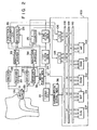
- Fig. 2 is a block diagram illustrating an overall arrangement of the embodiment used together with the conduit shown in Fig. 1;
- Fig. 3 shows timing diagrams of signals at the respective portions of the embodiment shown in Fig. 2; and
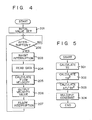
- Figs. 4 and 5 illustrate flow charts useful in explaining the operation of the embodiment shown in Fig. 2.
- A structure of a conduit provided with a pair of ultrasonic transducers used in an embodiment of a respiration flowmeter according to the present invention will first be described referring to Fig. 1. In the figure, an expiration gas, for example, flows through a
conduit 11, which is made of polycarbonate, for example, and has an inner diameter D, along its axis and at a flow velocity V in the direction of an arrow. Theconduit 11 may also be made of metal or plastic. Accordingly, the inspiration gas flows at a flow velocity V' in the opposite direction to that of the arrow. A pair ofrecesses 12a and 12b are provided on the inner wall of theconduit 11 along a line slanted at a center of the respiration gas flow, for example, with respect to the gas flow. A pair ofultrasonic transducers recesses 12a and 12b, facing at their transmitting and receiving surfaces each other along the slant line. Lead wires (not shown) for leading drive signals to theultrasonic transducers ultrasonic transducers recesses 12a and 12b to thetransducers conduit 11 without being interrupted by the pair oftransducers recesses 12a and 12b are not influenced by a flow velocity of the respiration gas. Accordingly, a distance over which the propagating velocity is influenced by the flow velocity of the gas between thetransducers transducer 13a to thetransducer 13b in the respiration flow direction V is given by
transducer 13b to 13a is


- The sonic velocity C changes depending on temperature, humidity and gas composition of the respiration air. Accordingly, if the flow velocity of the respiration is measured by merely using the ultrasonic propagating time difference ΔT, the measured value is influenced by the above factors.
- Let us calculate the sonic velocity C by using the sum Ta of the two ultrasonic propagating times T1 and T2. Then,


- The equation (7) implies that the flow velocity V can be measured by measuring only the ultrasonic propagating time difference AT and the ultrasonic propagating time T1, independently of the sonic velocity C, that is, without directly accounting for effects by temperature, humidity and gas composition.
- In the structure shown in Fig. 1, an
electric heater 14 is mounted around theconduit 11 and/or thetransducers conduit 11. - An arrangement of an embodiment of the present inventoin will be described referring to a block diagram of a device shown in Fig. 2 and signal waveforms shown in Fig. 3. In Fig. 2, a pulse a (Fig. 3(a)) produced from a
timing circuit 21 for each time TO is applied to drivingcircuits 22 and 23, a firstclock generating circuit 24 and aT counter 25. The time TO designates a time in the order of several msec to 10 msec. The firstclock generating circuit 24 generates clock signals at 100 MHz, for example, for transfer to aAT counter 26 for counting the ultrasonic propagating time difference AT (0 to several µsec). TheT counter 25 counts a propagating time T1, and starts to count in response to the pulse a. The clock signal used for counting the propagating time T1 is supplied from a secondclock generating circuit 27. The secondclock generating circuit 27 is driven by an output signal from the firstclock generating circuit 24, and produces second clock signals at 10 MHz, which is, for example, 1/10 that of the first clock signals. - Upon receipt of the pulse a, the
driving circuits 22 and 23 generate signals b' and c' (Figs. 3(b) and 3(c)) for drivingultrasonic transducers ultrasonic transducers ultrasonic transducers conduit 11. The ultrasonic waves transmitted are received by thecorresponding transducers receivers Receivers pulse generating circuit 32, reject signals applied during a period Tm after theultrasonic transducers receivers ultrasonic transducers pulse generating circuit 32 is also driven by the output pulses from thetiming circuit 21 and produces pulses d (Fig. 3(d)). The output signals from thereceivers waveform shapers direction judgment circuit 35, theAT counter 26, and theT counter 25. - The
T counter 25 receives the output signal from thewaveform shaper 33 to terminate its counting which has been performed under drive of thetiming circuit 21. TheT counter 25 counts a time taken for an ultrasonic wave to travel from theultrasonic wave transducer 13a to thetransducer 13b (Fig. 3(e)). In the present embodiment, an inspiration condition is illustrated as shown in Fig. 2 in which a patient 10 breathes in the direction of the arrow. Under this condition, the signal b" goes ahead of the signal c", as shown in Fig. 3. In an expiration condition that the patient 10 breathes out, the signal c" goes ahead the signal b". - The
AT counter 26 starts its counting responsive to the leading signal of those output signals from thewavefrom shapers waveform shaper 33 in this case, and stops its counting responsive to the lagged signal, that is, the output signal from thewaveform shaper 34. In this way, thecounter 26 counts the ultrasonic propagating time difference ΔT, as shown in Fig. 3(f). - The
direction judging circuit 35 also receives output signals from thewaveform shapers circuit 35 judges that the respiration is the inspiration when the output signal from thewaveform shaper 33 leads ahead the output signal derived from thewaveform shaper 34. On the other hand, it judges that the respiration is the expiration when the former lags behind the latter. At this judgment, its output goes high (see Fig 3(g)) or low in level. Thedirection judging circuit 35 may be formed of a general flip-flop with a clear terminal. - At the time that the three data necessary for measuring the flow velocity, i.e. the direction of the respiration, the ultrasonic propagating time T1 and the ultrasonic propagating time difference AT, are measured, an interruption signal which is the output pulse a derived from the
timing circuit 21 delayed by time TD, 1 msec, for example, is applied from an interruption signal generating circuit 36 (see Fig. 3(h)). The interruption signal is a signal for driving anarithmetic circuit 100 so as to cause it to calculate a flow velocity by using the above three data. - The
arithmetic circuit 100 is comprised of a microprocessor (MP) 101, a read only memory (ROM) 102 for storing a program executed by thearithmetic circuit 100 and constants, a random access memory (RAM) 103 for storing the data produced during, before or after the execution of the program, an arithmetic processor (AP) 104 for executing the operations such as numerical operation, and ports (I/O) 105 and 106 for inputting the three data, and a digital to analog (D/A)converter 107 for producing a calculated flow velocity in the form of an analog signal. Those components are interconnected by a control bus 108, anaddress bus 109 and a data bus 110. - The
arithmetic circuit 100 proceeds with the operation in accordance with a flow chart shown in Fig. 4. - In a
step 201, following the power on, initial values are set in themicroprocessor 101, theports memory 102 and the like in thearithmetic circuit 100. Then, in astep 202, thearithmetic circuit 100 is in a standby mode for waiting the interruption signal. When the interruption pulse enters themicroprocessor 101, themicroprocessor 101 sets itself to be in an interruption inhibiting mode, in astep 203. In thenext step 204, themicroprocessor 101 fetches the data of the direction of the gas flow, the ultrasonic propagating time difference AT, and the ultrasonic propagating time T1 from theports RAM 102. For ease of explanation, the AT will be treated as data with a sign representing a direction of the gas flow. Then, in astep 205, themicroprocessor 101 executes a flow velocity of the gas in accordance with a flow chart shown in Fig. 5 by using the data in thestep 204. The resultant data of flow velocity is delivered from D/A converter 107 through thestep 206. Finally, in -astep 207, themicroprocessor 101 sets itself to be in an interruption permission mode and waits an interruption signal produced in the next transmission and reception of the ultrasonic wave. Through the repetition of the above-mentioned operation, the respiration flowmeter of the present embodiment can measure at a rate of about 100 times per second, a flow velocity and a direction of the pulsating gas flow which instantaneously change with the respiration. - The flow chart shown in Fig. 5 illustrating a process flow of the calculation of the flow velocity according to the equation (7) will be given hereinafter.
- In a
step 301, the ultrasonic propagating time T1 and the ultrasonic propagating time difference AT stored in theRAM 103 are set in the arithmetic processor (AP) 104 where the ultrasonic propagating time sum TA (=2T1 ―AT) is obtained. The AT used when the Ta is calculated has a sign representing the flow direction, as described above, and a direction of the inspiration flow is represented by a negative sign in the present embodiment. - In a
step 302, an instruction for squaring the ultrasonic propagating time sum Ta is transferred to theAP 104 where Ta2 is calculated. In thenext step 303, the AT data is read out from theRAM 103 and set in theAP 104 where the ratio ΔT/Ta2 is calculated. Finally, in astep 304, the constant in the equation (7),
ROM 102 and is similarly set in theAP 104. Then, theMP 101 transfers an instruction to multiply the constant in the equation (7) by the ratio ΔT/Ta2 to theAP 104 where the flow rate is calculated. During the course of the operation, the data transmission between the ROM (102), the RAM (103) or the ports I/O microprocessor MP 101 is performed in a usual way. For example, theROM 102 is designated through theaddress bus 109; a control signal for data read or data write is transferred to theROM 102 through the control bus 108; the data to be read or written is transferred through the data bus 110. - As described above, the present invention successfully solves the problems of the prior art as previously stated and provides an almost ideal respiration flowmeter. It should be noted that, in the respiration flowmeter according to the present invention, the signal processing for the measurement is digitally performed, not through the D/A converting process, in the almost entire circuit portions except the ultrasonic transmitting and receiving portions. This feature eliminates the temperature drift which is problematic in the low flow rate measurement. Additionally, there is no need of the fine circuit adjustment essential to the analog circuit. This feature makes easy the manufacture of the flowmeter. Further, the analog to digital converter connected to the data processing is of course unnecessary, leading to simplification of the circuit construction, cost reduction and high reliability of the operation.
- Further, the respiration flowmeter of the present invention, which measures the flow velocity of the respiration by using the ultrasonic propagating time and the ultrasonic propagating time difference, allows the frequency of the clock signal to be selected for securing a measuring accuracy required for the measurement to be made. Therefore, the circuit construction is simple and an unnecessary high speed circuit is omitted. Further, the values thus measured are arranged in a minimum data length, so that the succeeding data process may be effectively performed.
- In the above-mentioned embodiment, the
receiver circuits ultrasonic transducers waveform shapers
Claims (3)

Applications Claiming Priority (4)
| Application Number | Priority Date | Filing Date | Title |
|---|---|---|---|
| JP153261/80 | 1980-10-31 | ||
| JP55153261A JPS5777914A (en) | 1980-10-31 | 1980-10-31 | Fluid measuring apparatus |
| JP153264/80 | 1980-10-31 | ||
| JP55153264A JPS5777915A (en) | 1980-10-31 | 1980-10-31 | Fluid measuring apparatus |
Publications (2)
| Publication Number | Publication Date |
|---|---|
| EP0051293A1 EP0051293A1 (en) | 1982-05-12 |
| EP0051293B1 true EP0051293B1 (en) | 1985-08-14 |
Family
ID=26481941
Family Applications (1)
| Application Number | Title | Priority Date | Filing Date |
|---|---|---|---|
| EP19810109303 Expired EP0051293B1 (en) | 1980-10-31 | 1981-10-29 | Respiration flowmeter |
Country Status (2)
| Country | Link |
|---|---|
| EP (1) | EP0051293B1 (en) |
| DE (1) | DE3171832D1 (en) |
Cited By (1)
| Publication number | Priority date | Publication date | Assignee | Title |
|---|---|---|---|---|
| DE4222286C1 (en) * | 1992-06-03 | 1994-05-11 | Reutter Georg Dr | Ultrasound spirometer |
Families Citing this family (8)
| Publication number | Priority date | Publication date | Assignee | Title |
|---|---|---|---|---|
| FR2551204B1 (en) * | 1983-04-12 | 1987-07-31 | Faes Yves | METHOD AND DEVICE FOR MEASURING THE TIME OF PROPAGATION OF A WAVE IN A FLOW AND APPLICATION TO A METHOD OF DETERMINING THE SPEED OF THIS FLOW |
| JPS60117131A (en) * | 1983-11-30 | 1985-06-24 | Toshiba Corp | Measuring tube for simultaneously measuring flow rate and concentration of fluid |
| GB2197472A (en) * | 1986-11-17 | 1988-05-18 | British Gas Plc | Ultrasonic flowmeter |
| ATE105080T1 (en) * | 1989-07-14 | 1994-05-15 | Haiges Elektronik Gmbh | METHOD OF MEASUREMENT OF A TIME DELAY OF ASSOCIATED ULTRASONIC SIGNALS AND RELATED MEASUREMENT ARRANGEMENTS. |
| DE19522697A1 (en) * | 1995-06-22 | 1997-01-09 | Sick Optik Elektronik Erwin | Method and circuit arrangement for measuring the flow velocity by means of acoustic transit time differences |
| WO1998004309A2 (en) * | 1996-07-27 | 1998-02-05 | Zygmunt Podolec | Device for controlled administration of medicines |
| DE102005015456A1 (en) * | 2005-04-04 | 2006-10-05 | Viasys Healthcare Gmbh | Wave packet`s temporal position determining method for e.g. spirometer, involves computing sum of product as product from value of comparison function and measurement value, and computing temporal position from sum of product |
| FR3098599B1 (en) * | 2019-07-12 | 2021-08-06 | Sagemcom Energy & Telecom Sas | Method of measuring the speed of a fluid |
Family Cites Families (6)
| Publication number | Priority date | Publication date | Assignee | Title |
|---|---|---|---|---|
| US3237453A (en) * | 1962-08-24 | 1966-03-01 | Tokyo Keiki Seizosho Company L | Ultrasonic flowmeter system |
| US3329017A (en) * | 1963-05-07 | 1967-07-04 | Tokyo Keiki Seizosho Co Ltd | Ultrasonic flow quantity measuring apparatus |
| US3918304A (en) * | 1973-11-23 | 1975-11-11 | Westinghouse Electric Corp | Flowmeter computer |
| US3922525A (en) * | 1974-05-13 | 1975-11-25 | Kozak Zdenek | Bidirectional spirometer |
| US4052896A (en) * | 1975-11-26 | 1977-10-11 | Badger Meter, Inc. | Ultrasonic flow meter |
| JPS5310454A (en) * | 1976-07-16 | 1978-01-30 | Nippon Kokan Kk | Apparatus for detecting change of fluid character by singgaround method |
-
1981
- 1981-10-29 DE DE8181109303T patent/DE3171832D1/en not_active Expired
- 1981-10-29 EP EP19810109303 patent/EP0051293B1/en not_active Expired
Cited By (1)
| Publication number | Priority date | Publication date | Assignee | Title |
|---|---|---|---|---|
| DE4222286C1 (en) * | 1992-06-03 | 1994-05-11 | Reutter Georg Dr | Ultrasound spirometer |
Also Published As
| Publication number | Publication date |
|---|---|
| DE3171832D1 (en) | 1985-09-19 |
| EP0051293A1 (en) | 1982-05-12 |
Similar Documents
| Publication | Publication Date | Title |
|---|---|---|
| US4425805A (en) | Respiration flowmeter | |
| US4024760A (en) | Fluid flow measurement apparatus | |
| EP0094148B1 (en) | Ultrasonic flowmeter | |
| US3564912A (en) | Fluid flow measurement system | |
| EP0100584A2 (en) | Ultrasonic flowmeter | |
| EP0051293B1 (en) | Respiration flowmeter | |
| EP0017475A1 (en) | Acoustic flowmeter with Reynolds number compensation | |
| US4391150A (en) | Electro-acoustic flowmeter | |
| US4078427A (en) | Ultrasonic flow or current meter | |
| EP0179541A2 (en) | Sonic flow meter | |
| JPH073346B2 (en) | Ultrasonic flowmeter measurement value processing method | |
| JPH063384B2 (en) | Ultrasonic flow meter | |
| KR100321074B1 (en) | Measuring method of distance between sensors of ultrasonic flowmeter | |
| JPH0561571B2 (en) | ||
| JPS6040916A (en) | Correcting method of temperature-change error of ultrasonic wave flow speed and flow rate meter | |
| JPS5897633A (en) | Temperature measurement system | |
| JP3521622B2 (en) | Ultrasonic flow meter and ultrasonic flow meter | |
| JPH073348B2 (en) | Method and apparatus for processing measured values of ultrasonic flowmeter | |
| GB2099146A (en) | A phase difference flowmeter | |
| JP3497279B2 (en) | Ultrasonic flow meter | |
| JPS5899717A (en) | Ultrasonic wave flowmeter | |
| JPH02116745A (en) | Ultrasonic solution density measuring apparatus | |
| JPS5927568B2 (en) | Breathing gas measuring device | |
| JPH0336889Y2 (en) | ||
| JPS62180220A (en) | Method and device for processing measured value of ultrasonic flow meter |
Legal Events
| Date | Code | Title | Description |
|---|---|---|---|
| PUAI | Public reference made under article 153(3) epc to a published international application that has entered the european phase |
Free format text: ORIGINAL CODE: 0009012 |
|
| 17P | Request for examination filed |
Effective date: 19811029 |
|
| AK | Designated contracting states |
Designated state(s): DE FR GB NL |
|
| RAP1 | Party data changed (applicant data changed or rights of an application transferred) |
Owner name: KABUSHIKI KAISHA TOSHIBA |
|
| GRAA | (expected) grant |
Free format text: ORIGINAL CODE: 0009210 |
|
| AK | Designated contracting states |
Designated state(s): DE FR GB NL |
|
| REF | Corresponds to: |
Ref document number: 3171832 Country of ref document: DE Date of ref document: 19850919 |
|
| ET | Fr: translation filed | ||
| PLBE | No opposition filed within time limit |
Free format text: ORIGINAL CODE: 0009261 |
|
| STAA | Information on the status of an ep patent application or granted ep patent |
Free format text: STATUS: NO OPPOSITION FILED WITHIN TIME LIMIT |
|
| 26N | No opposition filed | ||
| PGFP | Annual fee paid to national office [announced via postgrant information from national office to epo] |
Ref country code: GB Payment date: 19971020 Year of fee payment: 17 |
|
| PGFP | Annual fee paid to national office [announced via postgrant information from national office to epo] |
Ref country code: FR Payment date: 19981009 Year of fee payment: 18 |
|
| PGFP | Annual fee paid to national office [announced via postgrant information from national office to epo] |
Ref country code: NL Payment date: 19981028 Year of fee payment: 18 |
|
| PG25 | Lapsed in a contracting state [announced via postgrant information from national office to epo] |
Ref country code: GB Free format text: LAPSE BECAUSE OF NON-PAYMENT OF DUE FEES Effective date: 19981029 |
|
| GBPC | Gb: european patent ceased through non-payment of renewal fee |
Effective date: 19981029 |
|
| PG25 | Lapsed in a contracting state [announced via postgrant information from national office to epo] |
Ref country code: NL Free format text: LAPSE BECAUSE OF NON-PAYMENT OF DUE FEES Effective date: 20000501 |
|
| PG25 | Lapsed in a contracting state [announced via postgrant information from national office to epo] |
Ref country code: FR Free format text: LAPSE BECAUSE OF NON-PAYMENT OF DUE FEES Effective date: 20000630 |
|
| NLV4 | Nl: lapsed or anulled due to non-payment of the annual fee |
Effective date: 20000501 |
|
| REG | Reference to a national code |
Ref country code: FR Ref legal event code: ST |
|
| PGFP | Annual fee paid to national office [announced via postgrant information from national office to epo] |
Ref country code: DE Payment date: 20001023 Year of fee payment: 20 |