EP0051263A2 - Quick-change toolholder for lathes - Google Patents
Quick-change toolholder for lathes Download PDFInfo
- Publication number
- EP0051263A2 EP0051263A2 EP81109083A EP81109083A EP0051263A2 EP 0051263 A2 EP0051263 A2 EP 0051263A2 EP 81109083 A EP81109083 A EP 81109083A EP 81109083 A EP81109083 A EP 81109083A EP 0051263 A2 EP0051263 A2 EP 0051263A2
- Authority
- EP
- European Patent Office
- Prior art keywords
- tool holder
- quick
- holder
- clamping
- guide
- Prior art date
- Legal status (The legal status is an assumption and is not a legal conclusion. Google has not performed a legal analysis and makes no representation as to the accuracy of the status listed.)
- Granted
Links
Images

Classifications
-
- B—PERFORMING OPERATIONS; TRANSPORTING
- B23—MACHINE TOOLS; METAL-WORKING NOT OTHERWISE PROVIDED FOR
- B23B—TURNING; BORING
- B23B29/00—Holders for non-rotary cutting tools; Boring bars or boring heads; Accessories for tool holders
- B23B29/04—Tool holders for a single cutting tool
-
- Y—GENERAL TAGGING OF NEW TECHNOLOGICAL DEVELOPMENTS; GENERAL TAGGING OF CROSS-SECTIONAL TECHNOLOGIES SPANNING OVER SEVERAL SECTIONS OF THE IPC; TECHNICAL SUBJECTS COVERED BY FORMER USPC CROSS-REFERENCE ART COLLECTIONS [XRACs] AND DIGESTS
- Y10—TECHNICAL SUBJECTS COVERED BY FORMER USPC
- Y10T—TECHNICAL SUBJECTS COVERED BY FORMER US CLASSIFICATION
- Y10T82/00—Turning
- Y10T82/25—Lathe
- Y10T82/2572—Attachment
- Y10T82/2574—Stop [e.g., carriage, tool, work, etc.]
-
- Y—GENERAL TAGGING OF NEW TECHNOLOGICAL DEVELOPMENTS; GENERAL TAGGING OF CROSS-SECTIONAL TECHNOLOGIES SPANNING OVER SEVERAL SECTIONS OF THE IPC; TECHNICAL SUBJECTS COVERED BY FORMER USPC CROSS-REFERENCE ART COLLECTIONS [XRACs] AND DIGESTS
- Y10—TECHNICAL SUBJECTS COVERED BY FORMER USPC
- Y10T—TECHNICAL SUBJECTS COVERED BY FORMER US CLASSIFICATION
- Y10T82/00—Turning
- Y10T82/25—Lathe
- Y10T82/2585—Tool rest
Definitions
- the innovation relates to a quick-change tool holder for lathes, consisting of a basic holder and a tool holder for the tool holder, which can be positioned relative to each other on prismatic or round guides by abutment against an adjustable stop and can be clamped perpendicular to the guide level by means of a clamping device Actuators for the clamping device are arranged in the change holder.
- Such a tool holder is known from DE-OS 27 45 4o2, in which only one adjustment direction or two adjustment directions are provided depending on the type of application for a plunging tool (FIGS. 1-3) or a facing tool (FIGS. 4-6), in the latter case, the necessary adjustment and clamping means are identical, that is, they are also duplicated.
- tools for multi-spindle automatic lathes are not double-adjustable and only one adjustment level is provided, which is arranged in such a way that the turning height can be adjusted with a stop screw (track, MULTI-SPINDLE LATHE-AUTOMATES, Carl Hanser Verlag, Kunststoff, Page 173).
- This generally customary arrangement of the guide level has the disadvantage that an adjustment of the workpiece dimensions is not possible.
- opposing threads are formed in axially separated areas, which engage in clamping jaws which are guided in a non-rotatable manner in the interchangeable holder and which accordingly move towards one another when the screw is actuated. or moved away from each other.
- Wedge surfaces are formed on the clamping sides of these clamping jaws, which grip appropriately designed wedge surfaces of a sliding block arranged displaceably in a T-slot of the basic holder and are thereby able to clamp the interchangeable insert with respect to the basic holder.
- clamping screw is arranged transversely to the longitudinal axis of the holder in an interchangeable insert. If several interchangeable inserts have to be arranged close to each other on a plate-shaped basic holder, then access to the clamping device of most interchangeable inserts is blocked and the neighboring interchangeable inserts must first be removed before the clamping of an inner insert can be released.
- Both Ausqestaltungsformen the clamping device in DE-OS 27 45 4o7 also have the disadvantage that when the interchangeable insert is placed on the basic holder, the exact engagement between the clamping element and the sliding block cannot be monitored visually and cannot be produced by a long training of the sliding block, because a long sliding block requires a correspondingly long shifting of the change holder before lifting.
- the innovation is based on the object in a quick-change tool holder of the type mentioned with only one guide level, in which one or more prismatic or round guide means are provided, to arrange them so that a sufficient adjustability of the tool is made possible for all types of use.
- the clamping device should be improved so that the after Parts of the known tool holder can be avoided and with only a short actuation path, immediate loosening can take place both in the direction of the guide means and perpendicular to the guide plane.
- this object is achieved in that the guide means are arranged parallel to the clamping surface of the basic holder on the tool slide and at right angles to the main feed direction, in that the clamping device has an eccentric bolt which projects through a bore in a clamping piece, and in that the eccentric bolt is both rotatable in the interchangeable insert as well as axially displaceable in the main feed direction and is displaceable from an operative position to an ineffective position in which it releases the clamping piece which is displaceable in the basic holder in a T-slot by means of a sliding block, so that the interchangeable holder can be removed perpendicular to the guide plane.
- a quick-change tool holding system for a lathe requires three adjustment directions per se, namely the x-direction for the diameter adjustment, the y-direction for the height adjustment (turning height) and the z-direction for the length adjustment. If all three adjustment devices are arranged in the tool holder, which is technically possible - solutions with four-fold adjustment have already become known, including a swiveling movement - the costs are so high that the use of these tool holders is only economically justifiable in exceptional cases . In any case, these solutions are uneconomical for a quick-change tool holding system, which must be offered as normal accessories for a lathe.
- the innovation is therefore based on the consideration that it makes more sense to move one of these adjustment options into the lathe itself, namely the positioning of the basic holder in the feed direction, for example using path-limiting stops for the feed slide, and the formation of a slide bar upper part or the arrangement of adjustable stops for the basic holder on the slide. It follows from this that then only one adjustment option transverse to the feed direction is sufficient in the tool holder to nevertheless ensure adjustment in two directions (x and z direction). The resulting economic advantage of making use of the adjustment facility arranged in the machine for all tool holders is evident.
- the quick-change tool holder according to the invention can be used not only with mechanically or hydraulically operated lathes, in particular multi-spindle automatic lathes, but because of its economic advantages, e.g. can also be used with numerically controlled lathes. This provides a general applicability that further underlines the economic importance.
- a first advantageous embodiment results from the fact that the T-slot with the sliding block of the clamping piece is arranged asymmetrically between the two guides so that it is closer to the Tool cutting edge runs adjacent to the other guide.
- This configuration makes it possible, when using only one such clamping device, to safely absorb the tilting moments resulting from the attack of the turning tool on the workpiece and to transmit them to the basic holder.
- the eccentric pin is so spring-loaded in the axial direction that it is automatically displaced in the axial direction after the eccentric tension has been released. As a result, the state of the clamping device is displayed visibly from the outside.
- a special embodiment of the new clamping device results from the fact that the eccentric bolt has an axial groove and a radial groove adjoining one end thereof, into which a guide means arranged in the form of a screw or a pin engages. This prevents the eccentric bolt from being lost.
- the drawing shows a basic holder 1 with two circular guides 2 and an exchangeable insert 3 attachable thereon.
- the basic holder 1 is designed as a plate and has an attachment 4 with which it is inserted into a groove in a slide of a lathe and fastened by means of screws 5 and sliding blocks 6 can be.
- the tool (not shown), namely a lathe tool, is clamped in the insert 3 via a pressure plate 7 by means of clamping screws 8 in a known manner.
- the pressure plate 7 is held in the interchangeable insert 3 by a screw 1o loaded by a spring 9 so that it is constantly on the Clamping screws 8 abut and thus allow unhindered replacement of the tool.
- the position of the tool in the tool channel 11 can be adjusted using adjusting screws 12 and 13 (13a, 13b).
- a sliding block 15 is slidably inserted, which engages with a cylindrical extension 16 in a bore 17 of the interchangeable insert 3 and forms a standing piece.
- G parallel to the tool press channel 11 is alternately insert 3 an eccentric pin 18 mounted, the 19 interspersed with its eccentric portion 18a is a hole in the extension 16 of the sliding block 15 and is supported with a smaller diameter cylindrical end portion 18b in the change insert.
- a compression spring 2o which is fastened on its other end face 2oa in a suitable manner, for example by gluing, in the bore 21 receiving the end part 18b of the eccentric pin 18.
- the eccentric pin 18 contains a circumferential groove 22 and an axial groove 23 which opens at one end into the circumferential groove 22, extends through the eccentric part 18a and is closed on the end face before the end there.
- a screw 24 arranged in the interchangeable insert engages in the circumferential groove 22, so that the eccentric bolt 18 can only be rotated in this position, but cannot be axially displaced.
- the interchangeable insert 3 is clamped with the basic holder 1 or the clamp is released.
- the eccentric pin 18 If the eccentric pin 18 is rotated when loosening so that the screw 24 comes in front of the axial groove 23, then the eccentric pin 18 is automatically moved under the action of the spring 2o into a more protruding position from the interchangeable insert.
- the eccentric bolt 18 thus always assumes an externally recognizable position in the released state, which signals the installer to the release position.
- the groove 23 is formed so long that the extension 16 of the sliding block is released when the eccentric pin 18 is pulled out to the extreme position. In this position, the interchangeable insert 3 can be lifted off the basic holder 1 perpendicular to the circular guides 2. So that the sliding block 15 is not lost, a spring-loaded clamping bolt 25 is arranged in a known manner in its base, which secures the sliding block in the T-slot 14 in a frictionally locking manner.
- a further, preferably dovetail-shaped groove 26 is formed in the basic holder 1 transversely to the feed direction, in which a stop 27 is clamped by means of a threaded pin 28.
- the interchangeable insert 3 can be adjusted against this stop 27 by means of an adjusting screw 29.
- FIG. 5 shows the load conditions under the action of the cutting forces F, which is broken down into the components Fx and Fy.
- the forces involved in overhead machining are shown in dashed lines and indicated by an apostrophe.
Abstract
Description
Die Neuerung bezieht sich auf einen Schnellwechsel-Werkzeughalter für Drehmaschinen, bestehend aus einem Grundhalter und einem das Werkzeug aufnehmenden Wechseleinsatz, die relativ zueinander auf prismatischen oder runden Führungen durch Anlage gegen einen verstellbaren Anschlag positionierbar und mittels einer Klemmeinrichtung senkrecht zur Führungsebene verspannbar sind, wobei die Betätigungselemente für die Klemmeinrichtung im Wechselhalter angeordnet sind.The innovation relates to a quick-change tool holder for lathes, consisting of a basic holder and a tool holder for the tool holder, which can be positioned relative to each other on prismatic or round guides by abutment against an adjustable stop and can be clamped perpendicular to the guide level by means of a clamping device Actuators for the clamping device are arranged in the change holder.
Aus der DE-OS 27 45 4o2 ist ein derartiger Werkzeughalter bekannt, bei welchem in Abhängigkeit von der Anwendungsart für ein Einstechwerkzeug (Fig. 1-3) oder ein Plandrehwerkzeug (Fig. 4-6) nur eine Verstellrichtung oder zwei Verstellrichtungen vorgesehen sind, wobei im letzteren Fall die erforderlichen Verstell- und Klemmittel identisch ausgebildet, also ebenfalls doppelt vorhanden sind. Dies bedeutet, daß anstelle eines Wechseleinsatzes ebenfalls zwei auswechselbare Halteteile für das Werkzeug mit identischen Führungs-und Klemmitteln erforderlich werden. Dies hat eine erhebliche Verteuerung zur Folge und erfordert beim Anwender doppelte Lagerhaltung.Such a tool holder is known from DE-OS 27 45 4o2, in which only one adjustment direction or two adjustment directions are provided depending on the type of application for a plunging tool (FIGS. 1-3) or a facing tool (FIGS. 4-6), in the latter case, the necessary adjustment and clamping means are identical, that is, they are also duplicated. This means that instead of an interchangeable insert, two interchangeable holding parts for the tool with identical guiding and clamping means are also required. This results in considerable price increases and requires double storage for the user.
Aus diesen Gründen verzichtet man beispielsweise bei Werkzeugen für Mehrspindel-Drehautomaten auf die doppelte Verstellbarkeit und sieht nur eine Verstellebene vor, die so angeordnet ist, daß durch eine Anschlaqschraube die Drehhöhe eingestellt werden kann (Spur, MEHRSPINDEL-DREHAUTOMATEN, Carl Hanser Verlag, München, Seite 173). Dieser allgemein üblichen Anordnung der Führungsebene haftet der Nachteil an, daß eine Einstellung der Werkstückmaße nicht möglich ist.For these reasons, for example, tools for multi-spindle automatic lathes are not double-adjustable and only one adjustment level is provided, which is arranged in such a way that the turning height can be adjusted with a stop screw (track, MULTI-SPINDLE LATHE-AUTOMATES, Carl Hanser Verlag, Munich, Page 173). This generally customary arrangement of the guide level has the disadvantage that an adjustment of the workpiece dimensions is not possible.
Der aus der DE-OS 27 45 4o2 vorbekannte Schnellwechsel-Werkzeuqhalter weist auch eine im Wechseleinsatz angeordnete schraubenbetätigte Klemmeinrichtung (Finuren Z,3,7,8,9) auf.The previously known from DE-OS 27 45 4o2 quick-change Werkzeuqhalter also includes a change in the use s arranged on chraubenbetätigte clamping means (Finuren Z, 3,7,8,9).
An einer axial feststehenden Betätigunqsschraube sind in axial getrennten Bereichen gegenläufige Gewinde ausgebildet, die in undrehbar im Wechselhalter geführte Spannbacken eingreifen, welche demgemäß beim Betätigen der Schraube aufeinanderzu. oder voneinanderwegbewegt werden. An den Spannseiten dieser Spannbacken sind Keilflächen ausgebildet, die entsprechend ausgebildete Keilflächen eines in einer T-Nut des Grundhalters verschieblich angeordneten Nutensteins erfassen und dadurch den Wechseleinsatz gegenüber dem Grundhalter zu verspannen vermögen. Diese Ausbildung ermöglicht durch entsprechend weites Zurückstellen der Spannbacken, daß der Wechseleinsatz nicht nur in Richtung der Führunqen, sondern auch senkrecht zur Führungsebene entfernt werden kann, was im Hinblick auf die engen Platzverhältnisse im Arbeitsraum von z.B. Mehrspindel-Drehautomaten einen erheblichen Vorteil darstellt. Jedoch ist diese Ausbildung der Spanneinrichtung sehr aufwendig,und die Funktion der Klemmeinrichtung ist dann nicht gewährleistet, wenn der Nutenstein im Grundhalter verschieblich angeordnet ist, da bei aufgesetztem Wechselhalter der Nutenstein nicht mehr zu sehen ist und somit der exakte Angriff der Spannbacken am Stein nicht überwacht werden kann. Dies erfordert die Verwendung sehr langer und damit teuerer Nutensteine, oder es muß stattdessen ein mit dem Grundhalter einstückig ausgebildeter langer Steg mit schrägen Spannflächen vorgesehen werden.On an axially fixed actuating screw, opposing threads are formed in axially separated areas, which engage in clamping jaws which are guided in a non-rotatable manner in the interchangeable holder and which accordingly move towards one another when the screw is actuated. or moved away from each other. Wedge surfaces are formed on the clamping sides of these clamping jaws, which grip appropriately designed wedge surfaces of a sliding block arranged displaceably in a T-slot of the basic holder and are thereby able to clamp the interchangeable insert with respect to the basic holder. This training made possible by correspondingly wide reset of the jaws that the change insert can be removed for management level not only towards the Guide e q s, but also vertically, which multi-spindle automatic lathes represents a significant advantage in view of the limited space in the working area of eg. However, this design of the clamping device is very complex, and the function of the clamping device is not guaranteed if the sliding block is displaceably arranged in the basic holder, since when the interchangeable holder is attached, the sliding block can no longer be seen and therefore the exact attack of the clamping jaws on the stone is not monitored can be. This requires the use of very long and therefore expensive sliding blocks, or instead a long web with inclined clamping surfaces formed integrally with the basic holder must be provided.
Ein weiterer Nachteil der bekannten Klemmeinrichtung besteht darin, daß die Spannschraube quer zur Längsachse des Halters im Wechseleinsatz angeordnet ist. Müssen auf einem plattenförmigen Grundhalter mehrere Wechseleinsätze eng nebeneinander angeordnet werden, dann ist der Zugang zur Klemmeinrichtunq der meisten Wechseleinsätze versperrt, und es müssen erst die benachbarten Wechseleinsätze entfernt werden, bevor die Klemmung eines inneren Einsatzes gelöst werden kann.Another disadvantage of the known clamping device is that the clamping screw is arranged transversely to the longitudinal axis of the holder in an interchangeable insert. If several interchangeable inserts have to be arranged close to each other on a plate-shaped basic holder, then access to the clamping device of most interchangeable inserts is blocked and the neighboring interchangeable inserts must first be removed before the clamping of an inner insert can be released.
In der DE-OS 27 45 4o7 wird, vermutlich um diesen Nachteil zu beseitigen, auch noch vorqeschlagen (Fig. 6), die Klemmung von oben her zu betätigen, wobei mittels einer sich gegen die Oberseite des Wechseleinsatzes abstützenden Schraube ein im Gewindeeingriff mit dieser stehendes Spannelement verschoben wird, das über eine schwalbenschwanzförmiqe Ausnehmung am unteren Ende den im Grundhalter angeordneten und den mit entsprechenden Keilflächen versehenen Nutenstein erfaßt. Dieser Lösung haftet der Nachteil an, daß der Wechseleinsatz nach dem Lösen der Schraube entweder ebenfalls in Richtung der Führungsebene verschoben werden muß, um das Spannelement vom Nutenstein zu trennen, oder der Wechseleinsatz nach Lösen der Spannschraube oder einer radial geschlitzten Unterlegscheibe vom Spannelement abgehoben werden muß, was große Mühe beim Wiederaufsetzen bereitet.In DE-OS 27 45 4o7, presumably in order to eliminate this disadvantage, it is also proposed (Fig. 6) to actuate the clamping from above, with a screw which is supported against the top of the interchangeable insert in threaded engagement with it standing clamping element is moved, which detects the dovetail arranged in the basic holder and provided with the corresponding wedge surfaces via a dovetail-shaped recess at the lower end. This solution has the disadvantage that after the screw has been loosened, the interchangeable insert must either also be displaced in the direction of the guide plane in order to separate the clamping element from the sliding block, or the interchangeable insert must be lifted off the clamping element after loosening the clamping screw or a radially slotted washer , which is very difficult when you put it back on.
Beide Ausqestaltungsformen der Klemmeinrichtung bei der DE-OS 27 45 4o7 haben außerdem den Nachteil, daß beim Aufsetzen des Wechseleinsatzes auf den Grundhalter der exakte Eingriff zwischen Spannelement und Nutenstein nicht visuell überwachbar ist und auch nicht durch eine lange Ausbildung des Nutensteins hergestellt werden kann, denn ein langer Nutenstein erfordert ein entsprechend langes Verschieben des Wechselhalters vor dem Abheben. Darüber hinaus wirkt sich nachteilig aus, daß die Verschieberichtung von der Drehspindel weg durch den Anschlag blockiert ist, so daß der Wechseleinsatz beim Entfernen immer zur Drehspindel hin geschoben werden muß.Both Ausqestaltungsformen the clamping device in DE-OS 27 45 4o7 also have the disadvantage that when the interchangeable insert is placed on the basic holder, the exact engagement between the clamping element and the sliding block cannot be monitored visually and cannot be produced by a long training of the sliding block, because a long sliding block requires a correspondingly long shifting of the change holder before lifting. In addition, it is disadvantageous that the direction of displacement away from the rotating spindle is blocked by the stop, so that the interchangeable insert must always be pushed toward the rotating spindle during removal.
Der Neuerung liegt die Aufgabe zugrunde, bei einem Schnellwechsel-Werkzeughalter der eingangs genannten Art mit nur einer Führungsebene, in der ein oder mehrere prismatische oder runde Führungsmittel vorgesehen sind, diese so anzuordnen, daß eine für alle Einsatzarten ausreichende Einstellbarkeit des Werkzeuges ermöglicht wird. Außerdem soll die Klemmeinrichtung dahingehend verbessert werde, daß die Nachteile der bekannten Werkzeughalter vermieden werden und bei nur kurzem Betätigungsweg ein unmittelbares Lösen sowohl in Richtung der Führungsmittel als auch senkrecht zur Führungsebene erfolgen kann.The innovation is based on the object in a quick-change tool holder of the type mentioned with only one guide level, in which one or more prismatic or round guide means are provided, to arrange them so that a sufficient adjustability of the tool is made possible for all types of use. In addition, the clamping device should be improved so that the after Parts of the known tool holder can be avoided and with only a short actuation path, immediate loosening can take place both in the direction of the guide means and perpendicular to the guide plane.
Die Lösung dieser Aufgabe erfolgt neuerungsgemäß dadurch, daß die Führungsmittel parallel zur Aufspannfläche des Grundhalters auf dem Werkzeugschlitten und rechtwinkelig zur Hauptvorschubrichtung angeordnet sind, daß die Klemmeinrichtung, einen Exzenterbolzen aufweist, der eine Bohrung in einem Spannstück durchragt, und daß der Exzenterbolzen im Wechseleinsatz sowohl drehbar als auch in Hauptvorschubrichtung axial verschiebbar gelagert ist und aus einer Wirkungsstellung in eine wirkungslose Stellung verschiebbar ist, in welcher er das im Grundhalter in einer T-Nut mittels eines Nutensteins verschiebliche Spannstück freigibt, so daß der Wechselhalter senkrecht zur Führungsebene abnehmbar ist.According to the innovation, this object is achieved in that the guide means are arranged parallel to the clamping surface of the basic holder on the tool slide and at right angles to the main feed direction, in that the clamping device has an eccentric bolt which projects through a bore in a clamping piece, and in that the eccentric bolt is both rotatable in the interchangeable insert as well as axially displaceable in the main feed direction and is displaceable from an operative position to an ineffective position in which it releases the clamping piece which is displaceable in the basic holder in a T-slot by means of a sliding block, so that the interchangeable holder can be removed perpendicular to the guide plane.
Die Neuerung geht davon aus, daß ein Schnellwechsel-Werkzeughaltesystem für eine Drehmaschine an sich drei Verstellrichtungen erfordert, nämlich die x-Richtung für die Durchmessereinstellung, die y-Richtung für die Höheneinstellung (Drehhöhe) und die z-Richtung für die Längeneinstellung. Ordnet man alle drei Verstelleinrichtungen im Werkzeughalter an, was technisch durchaus möglich ist - es sind bereits Lösungen mit vierfacher Verstellung bekanntgeworden, wobei auch eine Schwenkbewegung berücksichtigt ist -, so ergeben sich so hohe Kosten, daß der Einsatz dieser Werkzeughalter nur in Ausnahmefällen wirtschaftlich vertretbar ist. Für ein Schnellwechsel-Werkzeughaltesystem, das als Normalzubehör für eine Drehmaschine angeboten werden muß, sind diese Lösungen in jedem Falle unwirtschaftlich. Die Neuerung geht deshalb von der Überlegung aus, daß es sinnvoller ist, eine dieser Verstellmöglichkeiten in die Drehmaschine selbst zu verlegen, und zwar die Positionierung des Grundhalters in Vorschubrichtung beispielsweise unter Verwendung von wegbegrenzenden Anschläqen für den Vorschubschlitten, die Ausbildung eines Schlittens mit einstellbarem Oberteil oder die Anordnung von verstellbaren Anschlägen für den Grundhalter auf dem Schlitten. Hieraus ergibt sich, daß dann im Werkzeughalter nur eine Verstellmöglichkeit quer zur Vorschubrichtung ausreichend ist, um dennoch eine Verstellung in zwei Richtungen (x- und z-Richtung) zu gewährleisten. Der sich daraus ergebende wirtschaftliche Vorteil, die in der Maschine angeordnete Verstellmöglichkeit für alle Werkzeughalter nutzbringend heranzuziehen, ist evident.The innovation assumes that a quick-change tool holding system for a lathe requires three adjustment directions per se, namely the x-direction for the diameter adjustment, the y-direction for the height adjustment (turning height) and the z-direction for the length adjustment. If all three adjustment devices are arranged in the tool holder, which is technically possible - solutions with four-fold adjustment have already become known, including a swiveling movement - the costs are so high that the use of these tool holders is only economically justifiable in exceptional cases . In any case, these solutions are uneconomical for a quick-change tool holding system, which must be offered as normal accessories for a lathe. The innovation is therefore based on the consideration that it makes more sense to move one of these adjustment options into the lathe itself, namely the positioning of the basic holder in the feed direction, for example using path-limiting stops for the feed slide, and the formation of a slide bar upper part or the arrangement of adjustable stops for the basic holder on the slide. It follows from this that then only one adjustment option transverse to the feed direction is sufficient in the tool holder to nevertheless ensure adjustment in two directions (x and z direction). The resulting economic advantage of making use of the adjustment facility arranged in the machine for all tool holders is evident.
Als weiterer Vorteil ergibt sich, daß der neuerungsgemäße Schnellwechsel-Werkzeughalter nicht nur bei mechanisch oder hydraulisch betätigten Drehmaschinen, insbesondere Mehrspindel-Drehautomaten anwendbar ist, sondern aufgrund seiner wirtschaftlichen Vorteile z.B. auch bei numerisch gesteuerten Drehmaschinen eingesetzt werden kann. Damit ist eine generelle Anwendbarkeit gegeben, die die wirtschaftliche Bedeutung weiter unterstreicht.Another advantage is that the quick-change tool holder according to the invention can be used not only with mechanically or hydraulically operated lathes, in particular multi-spindle automatic lathes, but because of its economic advantages, e.g. can also be used with numerically controlled lathes. This provides a general applicability that further underlines the economic importance.
Hervorzuheben ist ferner, daß sich durch die Beschränkung auf nur eine Verstellrichtung, die Anordnung der Führungsrichtung quer zur Vorschubrichtung und die besondere Ausbildung der Klemmeinrichtung mehrere Vorteile gleichzeitig einstellen:
- - die Wechseleinsätze können eng nebeneinander positioniert werden;
- - der Exzenterbolzen zum Lösen und Klemmen ist jederzeit zugänglich;
- - jeder Wechseleinsatz kann unabhängig von weiteren Einsätzen auf einfachem Wege senkrecht zur Führungsebene entfernt und in dieser Richtung wieder aufgesetzt werden;
- - es ist stets eine einwandfreie Klemmung gewährleistet, da der Exzenterbolzen das Spannstück durchdrinqt und somit unabhängig von der Verschiebbarkeit des Spannstücks immer eine eindeutige räumliche Zuordnung dieser Teile zueinander gewährleistet.
- - The interchangeable inserts can be positioned close to each other;
- - The eccentric bolt for loosening and clamping is accessible at all times;
- - Each interchangeable insert can be easily removed perpendicular to the guide plane and put back on in this direction, irrespective of further inserts;
- - A perfect clamping is always guaranteed, since the eccentric bolt penetrates the clamping piece and thus, regardless of the displaceability of the clamping piece, always ensures a clear spatial assignment of these parts to one another.
Gegenüber dem Stand der Technik (DE-AS 16 27 oo7) mit Anordnung des Exzenterbolzens im Grundhalter ergibt sich der weitere Vorteil, daß der Kraftangriffspunkt der Klemmkraft durch die unveränderliche Lage des Exzenters im Wechseleinsatz exakt definiert ist, während er sich beim Stande der Technik mit der Verstellung des Wechseleinsatzes verändert. Der neuerungsgemäße Werkzeughalter erlaubt deshalb auch wesentlich größere Verstellwege.Compared to the prior art (DE-AS 16 27 o7) with the arrangement of the eccentric bolt in the basic holder, there is the further advantage that the force application point of the clamping force is precisely defined by the unchangeable position of the eccentric in the interchangeable insert, while in the prior art with the adjustment of the change insert changed. The tool holder according to the innovation therefore also allows much longer adjustment paths.
Bei einem Schnellwechsel-Werkzeughalter gemäß der Neuerung mit zwei in Hauptvorschubrichtung beabstandeten prismatischen oder runden Führungen ergibt sich eine erste vorteilhafte Ausgestaltung dadurch, daß die T-Nut mit dem Nutenstein des Spannstücks derart asymmetrisch zwischen den beiden Führungen angeordnet ist, daß sie näher an der der Werkzeugschneide benachbarten Führung als der anderen Führung verläuft. Durch diese Ausgestaltung ist es möglich, bei Verwendung nur einer einzigen derartigen Klemmeinrichtung dennoch die vom Angriff des Drehmeißels am Werkstück herrührenden Kippmomente sicher aufzufangen und auf dem Grundhalter zu übertragen.In a quick-change tool holder according to the innovation with two prismatic or round guides spaced apart in the main feed direction, a first advantageous embodiment results from the fact that the T-slot with the sliding block of the clamping piece is arranged asymmetrically between the two guides so that it is closer to the Tool cutting edge runs adjacent to the other guide. This configuration makes it possible, when using only one such clamping device, to safely absorb the tilting moments resulting from the attack of the turning tool on the workpiece and to transmit them to the basic holder.
Nach einem anderen Ausgestaltungsmerkmal der Neuerung ist der Exzenterbolzen in Axialrichtung so federbelastet, daß er nach dem Lösen der Exzenterverspannung selbsttätig in Axialrichtung verschoben wird. Dadurch wird der Zustand der Klemmeinrichtung nach außen sichtbar angezeigt.According to another design feature of the innovation, the eccentric pin is so spring-loaded in the axial direction that it is automatically displaced in the axial direction after the eccentric tension has been released. As a result, the state of the clamping device is displayed visibly from the outside.
Eine besondere Ausgestaltung der neuerungsgemäßen Klemmeinrichtung ergibt sich ferner dadurch, daß der Exzenterbolzen eine Axialnut und eine an das eine Ende derselben anschließende Radialnut aufweist, in die ein im Wechseleinsatz angeordnetes Führungsmittel in Gestalt einer Schraube oder eines Stiftes eingreift. Auf diesem Wege wird verhindert, daß der Exzenterbolzen verlorengeht.A special embodiment of the new clamping device results from the fact that the eccentric bolt has an axial groove and a radial groove adjoining one end thereof, into which a guide means arranged in the form of a screw or a pin engages. This prevents the eccentric bolt from being lost.
Ein Ausführungsbeispiel des neuerungsgemäßen Schnellwechsel-Werkzeughalters wird nachstehend in Verbindung mit der Zeichnung näher erläutert. Es zeigen:
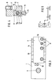
- Fig. 1: in voneinander getrennter Darstellung und teilweise im Schnitt eine Seitenansicht des Grundhalters und des Wechseleinsatzes des Schnellwechsel-Werkzeughalters,
- Fig. 2: einen Schnitt durch den Grundhalter und den Wechseleinsatz nach Linie II-II in Fig. 1,
- Fig. 3: eine Draufsicht auf den montierten Schnellwechsel-Werkzeughalter,
- Fig. 4: einen Schnitt durch den Wechseleinsatz nach IV-IV in Fig. 1 und
- Fig. 5: eine Darstellung der Momentverhältnisse bei Vorkopf- und Uberkopfbearbeitung.
- 1: in a separate representation and partially in section, a side view of the basic holder and the changing insert of the quick-change tool holder,
- 2: a section through the basic holder and the interchangeable insert according to line II-II in FIG. 1,
- 3: a top view of the assembled quick-change tool holder,
- Fig. 4: a section through the interchangeable insert according to IV-IV in Fig. 1 and
- Fig. 5: a representation of the momentary relationships in pre-head and overhead machining.
Die Zeichnung zeigt einen Grundhalter 1 mit zwei Rundführungen 2 und eiren darauf anbringbaren Wechseleinsatz 3. Der Grundhalter 1 ist als Platte ausgebildet und weist einen Ansatz 4 auf, mit dem er in eine Nut eines Schlittens einer Drehmaschine eingesetzt und mittels Schrauben 5 und Nutensteinen 6 befestigt werden kann.The drawing shows a basic holder 1 with two
Das (nicht gezeigte) Werkzeug, nämlich ein Drehmeißel,wird im Wechseleinsatz 3 über eine Druckplatte 7 mittels Spannschrauben 8 in bekannter Weise eingespannt. Die Druckplatte 7 ist im Wechseleinsatz 3 über eine durch eine Feder 9 belastete Schraube 1o so gehalten, daß sie ständig an den Spannschrauben 8 anliegt und somit ein unbehindertes Auswechseln des Werkzeugs ermöglicht. Die Position des Werkzeugs im Werkzeugkanal 11 kann durch Einstellschrauben 12 und 13 (13a, 13b) justiert werden.The tool (not shown), namely a lathe tool, is clamped in the
In einer Nut 14 des Grundhalters 1, die T- oder schwalbenschwanzförmig ausgebildet sein kann, ist ein Nutenstein 15 verschieblich eingesetzt, der mit einem zylindrischen Fortsatz 16 in eine Bohrung 17 des Wechseleinsatzes 3 eingreift und ein Standstück bildet. Parallel zum Werkzeugkanal 11 ist im Wechseleinsatz 3 ein Exzenterbolzen 18 gelagert, der mit seinem exzentrischen Teil 18a eine Bohrung 19 im Fortsatz 16- des Nutensteins 15 durchsetzt und mit einem im Durchmesser kleineren zylindrischen Endteil 18b im Wechseleinsatz 3 gelagert ist.In a
An dem Exzenterbolzen 18 greift stirnseitig eine Druckfeder 2o an, die an ihrer anderen Stirnseite 2oa in der den Endteil 18b des Exzenterbolzens 18 aufnehmenden Bohrung 21 in geeigneter Weise, z.B. durch Kleben, befestigt ist. Der Exzenterbolzen 18 enthält eine Umfangsnut 22 und eine Axialnut 23, die mit ihrem einen Ende in die Umfangsnut 22 mündet, sich durch den exzentrischen Teil 18a erstreckt und vor dem dortigen Ende stirnseitig geschlossen ist. In der Wirkstellung des Exzenterbolzens greift eine im Wechseleinsatz angeordnete Schraube 24 in die Umfangsnut 22 ein, so daß der Exzenterbolzen 18 in dieser Stellung nur verdreht, jedoch nicht axial verschoben werden kann. Durch das Verdrehen wird der Wechseleinsatz 3 mit dem Grundhalter 1 geklemmt oder die Klemmung gelöst. Wird der Exzenterbolzen 18 beim Lösen soweit gedreht, daß die Schraube 24 vor die Axialnut 23 gelangt, dann wird der Exzenterbolzen 18 unter der Wirkung der Feder 2o selbsttätig in eine aus dem Wechseleinsatz stärker vorstehende Stellung verschoben. Der Exzenterbolzen 18 nimmt somit im gelösten Zustand immer eine von außen erkennbare Stellung ein, die dem Einrichter die Lösestellung signalisiert. Die Nut 23 ist so lang ausgebildet, daß der Fortsatz 16 des Nutensteins freigegeben wird, wenn der Exzenterbolzen 18 in die äußerste Position herausgezogen ist. In dieser Position kann der Wechseleinsatz 3 senkrecht zu den Rundführungen 2 vom Grundhalter 1 abgehoben werden. Damit der Nutenstein 15 nicht verlorengeht, ist in seiner Grundfläche ein federbelasteter Klemmbolzen 25 in bekannter Weise angeordnet, der den Nutenstein reibungsschlüssig in der T-Nut 14 sichert.On the
Im Grundhalter 1 ist eine weitere, vorzugsweise schwalbenschwanzförmige Nut 26 quer zur Vorschubrichtung ausgebildet, in der ein Anschlag 27 mittels Gewindestift 28 festgeklemmt ist. Gegen diesen Anschlag 27 ist der Wechseleinsatz 3 mittels einer Einstellschraube 29 justierbar.A further, preferably dovetail-shaped
In Fig. 5 sind die Belastungsverhältnisse unter der Einwirkung der Zerspanunkrafte F dargestellt, die in die Komponenten Fx und Fy zerlegt wird. Die Kräfte bei der Uberkopfbearbeitung sind gestrichelt eingezeichnet und durch Apostroph gekennzeichnet. Bildet man für den Normalfall der Vorkopf-Bearbeitung die Momente um den Lagerpunkt A, der der drehspindelseitigen Rundführung entspricht, so erkennt man, daß die Wirkungsrichtungen der Kräfte Fx und Fy entgegengesetzt zueinander sind und demgemäß im Lagerpunkt B eine verhältnismäßig geringe Auflagerkraft hervorrufen. Betrachtet man hingegen für den Fall der Uberkopfbearbeitung die Momente der Kräfte F'x und F'y um den Punkt B, so ergibt sich für die Auflagerkräfte in A, daß beide Kraftwirkungen gleichgerichtet sind und sich demgemäß addieren. Daraus wird ersichtlich, daß im Lagerpunkt A eine höhere Klemmkraft aufzubringen ist als in B. Ausgehend von dieser Überlegung ist die Aufnahmenut 14 für den Nutenstein 15 nicht mittig zwischen den Rundführungen angeordnet, sondern näher in Richtung zum Ort der Zerspanung verlagert, wie diese aus den Figuren 1 und 3 erkennbar ist.5 shows the load conditions under the action of the cutting forces F, which is broken down into the components Fx and Fy. The forces involved in overhead machining are shown in dashed lines and indicated by an apostrophe. Forming for the normal case, the pre-header processing, the moments about the supporting point A, which corresponds to the drehspindelseiti g en circular guide, it can be seen that the directions of action of the forces Fx and Fy are opposite to each other and accordingly, cause a relatively small reaction force in the bearing point B. If, on the other hand, one considers the moments of the forces F'x and F'y around point B in the case of overhead machining, it results for the support forces in A that both force effects are aligned and add up accordingly. From this it can be seen that a higher clamping force is to be applied in bearing point A than in B. Based on this consideration, the receiving
Claims (6)
Priority Applications (1)
| Application Number | Priority Date | Filing Date | Title |
|---|---|---|---|
| AT81109083T ATE17453T1 (en) | 1980-11-03 | 1981-10-28 | QUICK CHANGE TOOL HOLDER FOR LATHES. |
Applications Claiming Priority (2)
| Application Number | Priority Date | Filing Date | Title |
|---|---|---|---|
| DE19808029160U DE8029160U1 (en) | 1980-11-03 | 1980-11-03 | QUICK-CHANGE TOOL HOLDER FOR LATHE |
| DE8029160U | 1980-11-03 |
Publications (3)
| Publication Number | Publication Date |
|---|---|
| EP0051263A2 true EP0051263A2 (en) | 1982-05-12 |
| EP0051263A3 EP0051263A3 (en) | 1983-07-20 |
| EP0051263B1 EP0051263B1 (en) | 1986-01-15 |
Family
ID=6720235
Family Applications (1)
| Application Number | Title | Priority Date | Filing Date |
|---|---|---|---|
| EP81109083A Expired EP0051263B1 (en) | 1980-11-03 | 1981-10-28 | Quick-change toolholder for lathes |
Country Status (5)
| Country | Link |
|---|---|
| US (1) | US4515049A (en) |
| EP (1) | EP0051263B1 (en) |
| AT (1) | ATE17453T1 (en) |
| BR (1) | BR8106925A (en) |
| DE (2) | DE8029160U1 (en) |
Cited By (2)
| Publication number | Priority date | Publication date | Assignee | Title |
|---|---|---|---|---|
| EP0485662A1 (en) * | 1990-11-16 | 1992-05-20 | GÖLTENBODT PRÄZISIONSWERKZEUG- UND MASCHINENFABRIK GmbH & CO. | Method and device to change with presetting for chipcutting machines |
| CN103286602A (en) * | 2013-05-14 | 2013-09-11 | 六安市龙兴汽车零部件有限公司 | Multipurpose eccentric turning clamp for automotive transmission rear covers |
Families Citing this family (9)
| Publication number | Priority date | Publication date | Assignee | Title |
|---|---|---|---|---|
| US5367754A (en) * | 1991-03-29 | 1994-11-29 | Hardinge Brothers, Inc. | Gang tooling for a computerized numerically controlled lathe |
| DE10224126B4 (en) * | 2002-05-29 | 2004-05-13 | Ernst Graf | Multiple tool holder for a lathe, especially for a Swiss type automatic lathe |
| DE102005029140B4 (en) * | 2005-06-23 | 2008-04-03 | Elke Weigelt | Tool fastening device for a wedge drive |
| DE102005052314A1 (en) * | 2005-11-01 | 2007-05-03 | Satisloh Gmbh | Fast tool arrangement, in particular for lathes for processing optical workpieces |
| DE102006036654B4 (en) * | 2006-08-03 | 2008-12-04 | Harald Weigelt | Wedge drive with forced return device |
| US8430385B2 (en) * | 2007-09-24 | 2013-04-30 | Harald Weigelt | Wedge drive with slider receiving means |
| CN101524765B (en) * | 2009-04-13 | 2010-07-21 | 吴淼东 | Small inner bore lathe grooving tool |
| JP5539012B2 (en) * | 2010-05-17 | 2014-07-02 | 東芝機械株式会社 | Automatic tool changer for precision roll lathe |
| CN112548122B (en) * | 2020-12-07 | 2022-04-22 | 台州市路桥先创自动化设备有限公司 | Lathe machining device convenient for tool mounting |
Citations (2)
| Publication number | Priority date | Publication date | Assignee | Title |
|---|---|---|---|---|
| DE1939132A1 (en) * | 1969-08-01 | 1971-02-04 | Schiess Ag | Quick change tool holder |
| DE2150518A1 (en) * | 1971-10-09 | 1973-05-17 | Walter Goeltenbodt Kg | QUICK-CHANGE AND PRE-ADJUSTABLE TURNING CHISEL HOLDER FOR ROUND AND FLAT SHAPED CHISEL |
Family Cites Families (10)
| Publication number | Priority date | Publication date | Assignee | Title |
|---|---|---|---|---|
| US3107562A (en) * | 1963-10-22 | Tool head with removable tool holder | ||
| US2023869A (en) * | 1933-11-22 | 1935-12-10 | Sundstrand Machine Tool Co | Work supports for machine tools |
| US2763176A (en) * | 1953-07-09 | 1956-09-18 | Maurice J Chartier | Cross slide tool holder |
| US3163062A (en) * | 1962-07-25 | 1964-12-29 | Honeywell Inc | Tool holders |
| US3232153A (en) * | 1964-05-28 | 1966-02-01 | Gen Motors Corp | Adjustable tool block |
| US3503287A (en) * | 1967-03-17 | 1970-03-31 | Robert C Zeller | Tool and toolholder |
| US3545319A (en) * | 1969-02-03 | 1970-12-08 | Usm Corp | Tool block |
| US3822619A (en) * | 1969-08-29 | 1974-07-09 | Willen & Cie C | Tool holder assembly having means for selectively adjusting the position of the work tool |
| US4043229A (en) * | 1976-04-05 | 1977-08-23 | Devlieg Machine Company | Self-retracting tool |
| CH612869A5 (en) * | 1977-08-15 | 1979-08-31 | Emile Albert Minder |
-
1980
- 1980-11-03 DE DE19808029160U patent/DE8029160U1/en not_active Expired
-
1981
- 1981-10-23 US US06/314,228 patent/US4515049A/en not_active Expired - Fee Related
- 1981-10-27 BR BR8106925A patent/BR8106925A/en not_active IP Right Cessation
- 1981-10-28 AT AT81109083T patent/ATE17453T1/en not_active IP Right Cessation
- 1981-10-28 DE DE8181109083T patent/DE3173525D1/en not_active Expired
- 1981-10-28 EP EP81109083A patent/EP0051263B1/en not_active Expired
Patent Citations (2)
| Publication number | Priority date | Publication date | Assignee | Title |
|---|---|---|---|---|
| DE1939132A1 (en) * | 1969-08-01 | 1971-02-04 | Schiess Ag | Quick change tool holder |
| DE2150518A1 (en) * | 1971-10-09 | 1973-05-17 | Walter Goeltenbodt Kg | QUICK-CHANGE AND PRE-ADJUSTABLE TURNING CHISEL HOLDER FOR ROUND AND FLAT SHAPED CHISEL |
Cited By (2)
| Publication number | Priority date | Publication date | Assignee | Title |
|---|---|---|---|---|
| EP0485662A1 (en) * | 1990-11-16 | 1992-05-20 | GÖLTENBODT PRÄZISIONSWERKZEUG- UND MASCHINENFABRIK GmbH & CO. | Method and device to change with presetting for chipcutting machines |
| CN103286602A (en) * | 2013-05-14 | 2013-09-11 | 六安市龙兴汽车零部件有限公司 | Multipurpose eccentric turning clamp for automotive transmission rear covers |
Also Published As
| Publication number | Publication date |
|---|---|
| US4515049A (en) | 1985-05-07 |
| EP0051263A3 (en) | 1983-07-20 |
| EP0051263B1 (en) | 1986-01-15 |
| DE8029160U1 (en) | 1981-04-16 |
| ATE17453T1 (en) | 1986-02-15 |
| BR8106925A (en) | 1982-07-13 |
| DE3173525D1 (en) | 1986-02-27 |
Similar Documents
| Publication | Publication Date | Title |
|---|---|---|
| DE2339873C2 (en) | Arrangement for setting and securing a block carrying a cutting tip in a groove-shaped receptacle in the tool body of a cutting tool | |
| EP0117557B1 (en) | Workpiece pallet for machine tools | |
| DE3324312C2 (en) | Machine tool with tool changing device | |
| EP0051263B1 (en) | Quick-change toolholder for lathes | |
| DE2234389B2 (en) | Tool head of lathe non-rotary tool holder - locates with conical surface on retainer bar with springs engaging in its grooves | |
| DE2916272C2 (en) | Tool changing device of a hydraulic punch press | |
| DE3519754A1 (en) | TOOL CHANGING DEVICE FOR A MACHINE TOOL | |
| DE19643590A1 (en) | Boring tool | |
| DE19845386A1 (en) | Punch for machine tool has each pressure part intended for side support against clamping device | |
| EP0901884A1 (en) | Clamping device, specially vice | |
| DE3528943C1 (en) | Top jaw for chuck | |
| DE3246994C2 (en) | ||
| DE4207353A1 (en) | TOOL HOLDER FOR A CUTTING TOOL | |
| DE2427413C3 (en) | Multiple tool holders for lathes | |
| EP0421069B1 (en) | Locating device | |
| EP0623420A1 (en) | Transporting and locating device | |
| EP0189528A1 (en) | Chuck for machine tools | |
| DE2100860A1 (en) | Tool holders on machine tools | |
| DE102019112337A1 (en) | Tool holding device | |
| DE3320851A1 (en) | Machine tool | |
| DE2700726C2 (en) | Lathe | |
| DE2808272C2 (en) | Chuck | |
| DE19739269C1 (en) | Machine tool clamping table | |
| DE3634364C2 (en) | ||
| DE2745402A1 (en) | TOOL HOLDER FOR A MACHINE TOOL |
Legal Events
| Date | Code | Title | Description |
|---|---|---|---|
| PUAI | Public reference made under article 153(3) epc to a published international application that has entered the european phase |
Free format text: ORIGINAL CODE: 0009012 |
|
| AK | Designated contracting states |
Designated state(s): AT CH DE FR GB IT SE |
|
| PUAL | Search report despatched |
Free format text: ORIGINAL CODE: 0009013 |
|
| AK | Designated contracting states |
Designated state(s): AT CH DE FR GB IT LI SE |
|
| 17P | Request for examination filed |
Effective date: 19830729 |
|
| ITF | It: translation for a ep patent filed |
Owner name: STUDIO INGG. FISCHETTI & WEBER |
|
| GRAA | (expected) grant |
Free format text: ORIGINAL CODE: 0009210 |
|
| AK | Designated contracting states |
Designated state(s): AT CH DE FR GB IT LI SE |
|
| REF | Corresponds to: |
Ref document number: 17453 Country of ref document: AT Date of ref document: 19860215 Kind code of ref document: T |
|
| REF | Corresponds to: |
Ref document number: 3173525 Country of ref document: DE Date of ref document: 19860227 |
|
| ET | Fr: translation filed | ||
| PGFP | Annual fee paid to national office [announced via postgrant information from national office to epo] |
Ref country code: AT Payment date: 19861015 Year of fee payment: 6 |
|
| PLBE | No opposition filed within time limit |
Free format text: ORIGINAL CODE: 0009261 |
|
| STAA | Information on the status of an ep patent application or granted ep patent |
Free format text: STATUS: NO OPPOSITION FILED WITHIN TIME LIMIT |
|
| 26N | No opposition filed | ||
| PG25 | Lapsed in a contracting state [announced via postgrant information from national office to epo] |
Ref country code: AT Effective date: 19871028 |
|
| PG25 | Lapsed in a contracting state [announced via postgrant information from national office to epo] |
Ref country code: SE Effective date: 19871029 |
|
| PG25 | Lapsed in a contracting state [announced via postgrant information from national office to epo] |
Ref country code: LI Effective date: 19871031 Ref country code: CH Effective date: 19871031 |
|
| GBPC | Gb: european patent ceased through non-payment of renewal fee | ||
| PG25 | Lapsed in a contracting state [announced via postgrant information from national office to epo] |
Ref country code: FR Free format text: LAPSE BECAUSE OF NON-PAYMENT OF DUE FEES Effective date: 19880630 |
|
| REG | Reference to a national code |
Ref country code: CH Ref legal event code: PL |
|
| REG | Reference to a national code |
Ref country code: FR Ref legal event code: ST |
|
| PG25 | Lapsed in a contracting state [announced via postgrant information from national office to epo] |
Ref country code: GB Effective date: 19881118 |
|
| EUG | Se: european patent has lapsed |
Ref document number: 81109083.6 Effective date: 19880707 |
|
| PGFP | Annual fee paid to national office [announced via postgrant information from national office to epo] |
Ref country code: DE Payment date: 19951223 Year of fee payment: 15 |
|
| PG25 | Lapsed in a contracting state [announced via postgrant information from national office to epo] |
Ref country code: DE Effective date: 19970701 |