EP0051025B1 - Dispositif de fractionnement de pièces métalliques - Google Patents
Dispositif de fractionnement de pièces métalliques Download PDFInfo
- Publication number
- EP0051025B1 EP0051025B1 EP81401661A EP81401661A EP0051025B1 EP 0051025 B1 EP0051025 B1 EP 0051025B1 EP 81401661 A EP81401661 A EP 81401661A EP 81401661 A EP81401661 A EP 81401661A EP 0051025 B1 EP0051025 B1 EP 0051025B1
- Authority
- EP
- European Patent Office
- Prior art keywords
- combs
- cutting apparatus
- sub
- teeth
- supports
- Prior art date
- Legal status (The legal status is an assumption and is not a legal conclusion. Google has not performed a legal analysis and makes no representation as to the accuracy of the status listed.)
- Expired
Links
- 210000001520 comb Anatomy 0.000 claims description 7
- 239000012634 fragment Substances 0.000 claims description 3
- 239000002184 metal Substances 0.000 description 5
- 239000004020 conductor Substances 0.000 description 2
- 231100000331 toxic Toxicity 0.000 description 2
- 230000002588 toxic effect Effects 0.000 description 2
- 229910001369 Brass Inorganic materials 0.000 description 1
- OKTJSMMVPCPJKN-UHFFFAOYSA-N Carbon Chemical compound [C] OKTJSMMVPCPJKN-UHFFFAOYSA-N 0.000 description 1
- 239000010951 brass Substances 0.000 description 1
- 230000003750 conditioning effect Effects 0.000 description 1
- 230000000694 effects Effects 0.000 description 1
- 238000005194 fractionation Methods 0.000 description 1
- 229910002804 graphite Inorganic materials 0.000 description 1
- 239000010439 graphite Substances 0.000 description 1
- 238000012423 maintenance Methods 0.000 description 1
- 239000007769 metal material Substances 0.000 description 1
- 238000004806 packaging method and process Methods 0.000 description 1
- 238000004064 recycling Methods 0.000 description 1
- 238000010008 shearing Methods 0.000 description 1
- 229910001220 stainless steel Inorganic materials 0.000 description 1
Images
Classifications
-
- B—PERFORMING OPERATIONS; TRANSPORTING
- B23—MACHINE TOOLS; METAL-WORKING NOT OTHERWISE PROVIDED FOR
- B23K—SOLDERING OR UNSOLDERING; WELDING; CLADDING OR PLATING BY SOLDERING OR WELDING; CUTTING BY APPLYING HEAT LOCALLY, e.g. FLAME CUTTING; WORKING BY LASER BEAM
- B23K11/00—Resistance welding; Severing by resistance heating
- B23K11/22—Severing by resistance heating
-
- B—PERFORMING OPERATIONS; TRANSPORTING
- B26—HAND CUTTING TOOLS; CUTTING; SEVERING
- B26F—PERFORATING; PUNCHING; CUTTING-OUT; STAMPING-OUT; SEVERING BY MEANS OTHER THAN CUTTING
- B26F3/00—Severing by means other than cutting; Apparatus therefor
- B26F3/06—Severing by using heat
Definitions
- the present invention relates to a device for splitting metal parts. It applies to the splitting of metal parts with a view to their conditioning, recycling or storage.
- the thermal machines can be cutting torches or plasma torches for example. They can also be of the thermoelectric type, as described in patent application EP-A-0 001 557. This type of machine does not allow multiple splitting of parts. In addition, its implementation is impractical since the piece to be cut must be maintained on a support. These different machines also have the disadvantage of wearing out quickly; in the case of mechanical machines, when filiform objects (wires, small tubes, springs, etc.) have to be split, these objects often get stuck in the moving parts of the machine, which are used for shearing. These machines are also very difficult to maintain, especially in hostile environments (toxic, dusty ).
- the object of the present invention is to remedy these drawbacks and in particular to produce a device for splitting metal parts, of the thermoelectric type, by means of which any jamming of the parts to be split is avoided, this device also being able to operate in a hostile environment.
- thermoelectric type fractionation device for filiform metallic parts in bars or tubes, comprising at least two conductive supports connected to an electrical power source and capable of at least partially supporting the part to be fractionated, characterized in that said piece comes to fall on the supports to be split simultaneously into several fragments, the conductive supports being constituted by two combs, the teeth of which are respectively nested to form a hopper receiving the piece to be split by contact with at least part of the teeth of two combs.
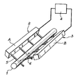
- This device allows the splitting of metal parts such as parts 1, of threadlike appearance; it comprises at least two supports 2, 3 conductors connected to an electrical power source 4; these conductors are capable of at least partially supporting the part to be split.
- the two supports 1, 2 are formed by combs, the teeth 5, 6 of which are nested so as to give the assembly the shape of a hopper. Any metallic object and in particular any filiform metallic piece falling into this hopper causes a short circuit between the teeth of the two combs; this object is thus split either by Joule effect or by sparkling.
- the device of the invention in this first embodiment, has the advantage of being very simple, of very easy maintenance and can operate in a hostile environment.
- the device which has just been described makes it possible to condition, for example, metallic wires or tubes of exchangers for example.
Landscapes
- Engineering & Computer Science (AREA)
- Mechanical Engineering (AREA)
- Life Sciences & Earth Sciences (AREA)
- Forests & Forestry (AREA)
- Elimination Of Static Electricity (AREA)
- Crushing And Grinding (AREA)
- Manufacture And Refinement Of Metals (AREA)
Applications Claiming Priority (2)
| Application Number | Priority Date | Filing Date | Title |
|---|---|---|---|
| FR8022683A FR2492707A1 (fr) | 1980-10-23 | 1980-10-23 | Dispositif de fractionnement de pieces metalliques |
| FR8022683 | 1980-10-23 |
Publications (2)
| Publication Number | Publication Date |
|---|---|
| EP0051025A1 EP0051025A1 (fr) | 1982-05-05 |
| EP0051025B1 true EP0051025B1 (fr) | 1985-03-27 |
Family
ID=9247235
Family Applications (1)
| Application Number | Title | Priority Date | Filing Date |
|---|---|---|---|
| EP81401661A Expired EP0051025B1 (fr) | 1980-10-23 | 1981-10-21 | Dispositif de fractionnement de pièces métalliques |
Country Status (6)
| Country | Link |
|---|---|
| US (1) | US4447694A (enExample) |
| EP (1) | EP0051025B1 (enExample) |
| JP (1) | JPS57100883A (enExample) |
| CA (1) | CA1192620A (enExample) |
| DE (1) | DE3169582D1 (enExample) |
| FR (1) | FR2492707A1 (enExample) |
Families Citing this family (5)
| Publication number | Priority date | Publication date | Assignee | Title |
|---|---|---|---|---|
| US4628169A (en) * | 1983-11-16 | 1986-12-09 | Ch Ing Lung Hsieh | Mini electrical syringe needle destroyer |
| JPH031697U (enExample) * | 1990-05-10 | 1991-01-09 | ||
| JP2557016B2 (ja) * | 1993-07-15 | 1996-11-27 | 株式会社エス・マック | 注射針処理装置 |
| US5637238A (en) * | 1995-01-31 | 1997-06-10 | Innovative Medical Equipment, Inc. | Apparatus for electrical destruction of medical instruments |
| WO2019034092A1 (zh) * | 2017-08-17 | 2019-02-21 | 河南大学 | 一种可施加电场的辊压机 |
Family Cites Families (4)
| Publication number | Priority date | Publication date | Assignee | Title |
|---|---|---|---|---|
| FR599690A (fr) * | 1925-06-18 | 1926-01-18 | Appareils de cuisine électrique à chauffage direct | |
| US2606266A (en) * | 1949-03-29 | 1952-08-05 | Duch Gabriel Victor Alphonse | Method for cutting cables, tubes, bars, rods, and the like |
| US2966572A (en) * | 1958-11-17 | 1960-12-27 | Harry J Hobbs | Electric shaver |
| DE2746803C2 (de) * | 1977-10-18 | 1986-08-28 | Siemens AG, 1000 Berlin und 8000 München | Verfahren zum Trennen eines aus einer Vielzahl von Drähten bestehenden Seiles |
-
1980
- 1980-10-23 FR FR8022683A patent/FR2492707A1/fr active Granted
-
1981
- 1981-10-16 CA CA000388161A patent/CA1192620A/en not_active Expired
- 1981-10-19 US US06/312,773 patent/US4447694A/en not_active Expired - Fee Related
- 1981-10-21 EP EP81401661A patent/EP0051025B1/fr not_active Expired
- 1981-10-21 JP JP56167332A patent/JPS57100883A/ja active Pending
- 1981-10-21 DE DE8181401661T patent/DE3169582D1/de not_active Expired
Also Published As
| Publication number | Publication date |
|---|---|
| DE3169582D1 (en) | 1985-05-02 |
| CA1192620A (en) | 1985-08-27 |
| JPS57100883A (en) | 1982-06-23 |
| FR2492707B1 (enExample) | 1984-04-27 |
| EP0051025A1 (fr) | 1982-05-05 |
| FR2492707A1 (fr) | 1982-04-30 |
| US4447694A (en) | 1984-05-08 |
Similar Documents
| Publication | Publication Date | Title |
|---|---|---|
| EP0051025B1 (fr) | Dispositif de fractionnement de pièces métalliques | |
| ES2142378T3 (es) | Calentador electrico semiconductor y metodo para su fabricacion. | |
| FR2550411A1 (fr) | Support de voyant lumineux sur circuit imprime | |
| FR2492703A1 (fr) | Machine a decouper un materiau en feuille au moyen d'un faisceau laser | |
| CA1147933A (fr) | Procede de frittage de pieces tubulaires en ceramique | |
| US2978847A (en) | Abrasive cutting wheel | |
| FR2987288A1 (fr) | Tete d'un dispositif de decharge electrohydraulique par fil explose | |
| EP3464914A1 (fr) | Rondelle d'appui | |
| CH620618A5 (enExample) | ||
| FR2492276A1 (fr) | Dispositif de mouture a grande vitesse de matieres ou de biomasse | |
| EP1541506B1 (fr) | Dispositif de transfert de pièces à sole vibrante notamment de pièces à équilibre précaire | |
| FR2642706A1 (fr) | Roulette pour pied de meuble ou analogue permettant la decharge de l'electricite statique | |
| EP0342104B1 (fr) | Procédé de brasage au laser de pièces en un ou plusieurs métaux réfléchissant la lumière | |
| TR200200437A2 (tr) | Yiyecek malzemesinden parçacıklar üretme cihazı ve yöntemi. | |
| FR2470663A1 (enExample) | ||
| FR2779077A1 (fr) | Dispositif d'arrachement des embouts des electrodes d'appareils de soudage | |
| FR2632764A1 (fr) | Dispositif de coupe pour cisaille a deplacement alternatif utilisee dans l'industrie nucleaire | |
| FR2598643A1 (fr) | Perfectionnement a un procede de soudage par resistance de toles, notamment d'acier | |
| FR2482297A1 (fr) | Manostat | |
| FR2536218A1 (fr) | Perfectionnements aux lasers a gaz | |
| FR2481972A1 (fr) | Procede et machine pour realiser une coupe plane biaise, d'angle aigu inferieur a 45o, d'une extremite d'un tube metallique | |
| EP4202569A1 (fr) | Boîte de montre avec lunette tournante | |
| FR2575695A1 (fr) | Filiere, notamment pour l'extrusion de briques | |
| FR2770936A1 (fr) | Cosse de masse | |
| FR2570310A1 (fr) | Torche de soudage a l'arc sous flux gazeux |
Legal Events
| Date | Code | Title | Description |
|---|---|---|---|
| PUAI | Public reference made under article 153(3) epc to a published international application that has entered the european phase |
Free format text: ORIGINAL CODE: 0009012 |
|
| AK | Designated contracting states |
Designated state(s): BE DE GB IT |
|
| 17P | Request for examination filed |
Effective date: 19821008 |
|
| ITF | It: translation for a ep patent filed | ||
| GRAA | (expected) grant |
Free format text: ORIGINAL CODE: 0009210 |
|
| AK | Designated contracting states |
Designated state(s): BE DE GB IT |
|
| REF | Corresponds to: |
Ref document number: 3169582 Country of ref document: DE Date of ref document: 19850502 |
|
| PLBE | No opposition filed within time limit |
Free format text: ORIGINAL CODE: 0009261 |
|
| STAA | Information on the status of an ep patent application or granted ep patent |
Free format text: STATUS: NO OPPOSITION FILED WITHIN TIME LIMIT |
|
| 26N | No opposition filed | ||
| PG25 | Lapsed in a contracting state [announced via postgrant information from national office to epo] |
Ref country code: BE Effective date: 19871031 |
|
| BERE | Be: lapsed |
Owner name: COMMISSARIAT A L'ENERGIE ATOMIQUE ETABLISSEMENT D Effective date: 19871031 |
|
| GBPC | Gb: european patent ceased through non-payment of renewal fee | ||
| PG25 | Lapsed in a contracting state [announced via postgrant information from national office to epo] |
Ref country code: DE Effective date: 19880701 |
|
| PG25 | Lapsed in a contracting state [announced via postgrant information from national office to epo] |
Ref country code: GB Effective date: 19881118 |