EP0050754B1 - Vorrichtung zur Flüssigkeitsabfüllung bei Vakuumverpackungen - Google Patents
Vorrichtung zur Flüssigkeitsabfüllung bei Vakuumverpackungen Download PDFInfo
- Publication number
- EP0050754B1 EP0050754B1 EP19810107914 EP81107914A EP0050754B1 EP 0050754 B1 EP0050754 B1 EP 0050754B1 EP 19810107914 EP19810107914 EP 19810107914 EP 81107914 A EP81107914 A EP 81107914A EP 0050754 B1 EP0050754 B1 EP 0050754B1
- Authority
- EP
- European Patent Office
- Prior art keywords
- channel
- dressing liquid
- upper body
- filling unit
- lower body
- Prior art date
- Legal status (The legal status is an assumption and is not a legal conclusion. Google has not performed a legal analysis and makes no representation as to the accuracy of the status listed.)
- Expired
Links
- 239000007788 liquid Substances 0.000 title claims description 38
- 238000009461 vacuum packaging Methods 0.000 title claims description 5
- 238000012545 processing Methods 0.000 claims description 13
- 230000007704 transition Effects 0.000 claims description 8
- 230000000740 bleeding effect Effects 0.000 claims description 7
- 238000006073 displacement reaction Methods 0.000 claims description 7
- 238000004891 communication Methods 0.000 claims description 6
- 230000000750 progressive effect Effects 0.000 claims description 2
- 239000000047 product Substances 0.000 description 7
- 238000004806 packaging method and process Methods 0.000 description 6
- 241000239290 Araneae Species 0.000 description 4
- 230000008859 change Effects 0.000 description 3
- 230000008878 coupling Effects 0.000 description 2
- 238000010168 coupling process Methods 0.000 description 2
- 238000005859 coupling reaction Methods 0.000 description 2
- 239000006260 foam Substances 0.000 description 2
- 230000002452 interceptive effect Effects 0.000 description 2
- 239000012263 liquid product Substances 0.000 description 2
- 238000004519 manufacturing process Methods 0.000 description 2
- 239000002245 particle Substances 0.000 description 2
- 230000009471 action Effects 0.000 description 1
- 238000013459 approach Methods 0.000 description 1
- 239000000428 dust Substances 0.000 description 1
- 235000013399 edible fruits Nutrition 0.000 description 1
- 235000013305 food Nutrition 0.000 description 1
- 235000011389 fruit/vegetable juice Nutrition 0.000 description 1
- 238000012423 maintenance Methods 0.000 description 1
- 239000000463 material Substances 0.000 description 1
- 230000013011 mating Effects 0.000 description 1
- 239000002184 metal Substances 0.000 description 1
- 239000002923 metal particle Substances 0.000 description 1
- 238000002360 preparation method Methods 0.000 description 1
- 235000013324 preserved food Nutrition 0.000 description 1
- 238000000926 separation method Methods 0.000 description 1
- 230000035939 shock Effects 0.000 description 1
- 239000007787 solid Substances 0.000 description 1
- 239000000725 suspension Substances 0.000 description 1
- 239000006188 syrup Substances 0.000 description 1
- 235000020357 syrup Nutrition 0.000 description 1
- 238000013519 translation Methods 0.000 description 1
- 238000007666 vacuum forming Methods 0.000 description 1
- 235000013311 vegetables Nutrition 0.000 description 1
- 239000002699 waste material Substances 0.000 description 1
Images
Classifications
-
- B—PERFORMING OPERATIONS; TRANSPORTING
- B65—CONVEYING; PACKING; STORING; HANDLING THIN OR FILAMENTARY MATERIAL
- B65B—MACHINES, APPARATUS OR DEVICES FOR, OR METHODS OF, PACKAGING ARTICLES OR MATERIALS; UNPACKING
- B65B39/00—Nozzles, funnels or guides for introducing articles or materials into containers or wrappers
- B65B39/14—Nozzles, funnels or guides for introducing articles or materials into containers or wrappers movable with a moving container or wrapper during filling or depositing
- B65B39/145—Nozzles, funnels or guides for introducing articles or materials into containers or wrappers movable with a moving container or wrapper during filling or depositing in an endless path
-
- B—PERFORMING OPERATIONS; TRANSPORTING
- B65—CONVEYING; PACKING; STORING; HANDLING THIN OR FILAMENTARY MATERIAL
- B65B—MACHINES, APPARATUS OR DEVICES FOR, OR METHODS OF, PACKAGING ARTICLES OR MATERIALS; UNPACKING
- B65B31/00—Packaging articles or materials under special atmospheric or gaseous conditions; Adding propellants to aerosol containers
- B65B31/04—Evacuating, pressurising or gasifying filled containers or wrappers by means of nozzles through which air or other gas, e.g. an inert gas, is withdrawn or supplied
- B65B31/044—Evacuating, pressurising or gasifying filled containers or wrappers by means of nozzles through which air or other gas, e.g. an inert gas, is withdrawn or supplied the nozzles being combined with a filling device
-
- B—PERFORMING OPERATIONS; TRANSPORTING
- B67—OPENING, CLOSING OR CLEANING BOTTLES, JARS OR SIMILAR CONTAINERS; LIQUID HANDLING
- B67C—CLEANING, FILLING WITH LIQUIDS OR SEMILIQUIDS, OR EMPTYING, OF BOTTLES, JARS, CANS, CASKS, BARRELS, OR SIMILAR CONTAINERS, NOT OTHERWISE PROVIDED FOR; FUNNELS
- B67C3/00—Bottling liquids or semiliquids; Filling jars or cans with liquids or semiliquids using bottling or like apparatus; Filling casks or barrels with liquids or semiliquids
- B67C3/02—Bottling liquids or semiliquids; Filling jars or cans with liquids or semiliquids using bottling or like apparatus
- B67C3/16—Bottling liquids or semiliquids; Filling jars or cans with liquids or semiliquids using bottling or like apparatus using suction
-
- Y—GENERAL TAGGING OF NEW TECHNOLOGICAL DEVELOPMENTS; GENERAL TAGGING OF CROSS-SECTIONAL TECHNOLOGIES SPANNING OVER SEVERAL SECTIONS OF THE IPC; TECHNICAL SUBJECTS COVERED BY FORMER USPC CROSS-REFERENCE ART COLLECTIONS [XRACs] AND DIGESTS
- Y10—TECHNICAL SUBJECTS COVERED BY FORMER USPC
- Y10T—TECHNICAL SUBJECTS COVERED BY FORMER US CLASSIFICATION
- Y10T137/00—Fluid handling
- Y10T137/8593—Systems
- Y10T137/86493—Multi-way valve unit
- Y10T137/86863—Rotary valve unit
Definitions
- This invention relates to a dressing liquid filling unit for vacuum packaging and the like machines, according to the precharacterising part of claim 1.
- a dressing liquid commonly called "dressing liquid"
- dressing liquid may be juice from the product itself, a product preparation liquid, syrup, a conservation liquid, and include liquids having different viscosities and liquids with solid suspensions.
- Such packaging machines are set up to carry out a given sequence of operations including the creation of a vacuum in the can intended to contain the drained product, the filling of the can with dressing liquid - which is effected by "suction", that is through the vacuum in the can drawing in the dressing liquid from a suitably arranged dressing liquid reservoir.
- this can is subjected to a dressing liquid topping and level adjusting step whereby the dressing liquid is brought to the exact desired level, thereafter the vacuum is removed as may be still present inside the can by placing the latter in communication with the atmosphere.
- the topping stem may be omitted altogether, as being unnecessary when operating with a low temperature dressing liquid and without any risk of its tending to foam when vacuumed.
- the rotation of the upper body is generally accomplished by providing an upwardly extending axial rod above the upper body which is terminated with a cross or spider element effective, during the movement of the valving elements on the carousel, to successively engage with a cam which causes, at a suitable time, a rotation by 90° or submultiple of 90° of the upper body with respect to the lower body, thus providing the transition from one processing step to the next.
- a filling unit of this type having all the features of the precharacterising part of claim 1, is known from US-A-2542788.
- a further drawback is that the continued succession of impacts unavoidably results in the separation of metal particles which may flow in the air and get into the can along with the food product, which is obviously unacceptable.
- the task of this invention is to obviate the foregoing drawbacks by providing a dressing liquid filling unit for vacuum packaging and the like machines, which is so constructed as to produce the rotation of discrete portions of the upper body relatively to the lower body of the valving elements in a "soft" manner, that is without creating impact conditions but rather providing a short duration rotational movement in a guided manner, so as to reduce the machine noise emission, as well as the considerable wearing of the component parts.
- the filling unit according to the invention must be able to carry out, the transition to the various processing steps with a much shorter rotation between the upper body and lower body of the valving element than conventional rotational movements, and must be also simple construction-wise and of reduced and easier maintenance.
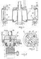
- a topper type of packaging machine incorporating the inventive dressing liquid filling unit comprises a carousel 1 rotatably carried in a base frame which has a plurality of uniformly distributed valving elements, generally indicated at 2 and being arranged in alignment with a plate 3 intended for supporting a can 4.
- Each of the cited valving elements includes a lower body 5 and upper body 6 overlying and being pivotable relative to the lower body 5.
- the lower body 5 is provided at the bottom with an annular seal 7 enabling its coupling in sealed relationship with the top mouth of the can 4 are carried on its corresponding plate 3.
- the cited lower body defines on its interior a main channel 10 open to the lower face of the body 7 and accordingly to the interior of the can 4, after the body 5 has been applied to the can, while the main channel 10 opens at the top to the flat upper face of the body 5.
- a suction channel 11 is defined which communicates to a vacuum source and to the upper face of the body 5.
- an auxiliary channel 12 open with its ends to the lower face and upper face, respectively, of the body 5, as well as an auxiliary air intake channel 13, also connected to a vacuum source.
- a compressed air delivery conduit 14 which opens to the upper face of the body 5 and communicates to a source of compressed air.
- a dressing liquid delivery channel 20 which opens to the flat lower face of the upper body 6, a main connection channel 21 communicating together, as will be explained hereinafter, various channels of the body 5, an auxiliary connection channel 22, and a bleeding channel 24 which communicates to the outside atmosphere to restore atmospheric pressure conditions within the can 4.
- the rod 30 is provided, at its free end, with an arm 32 which carries a cam following element, advantageously in the form of a roller 33.
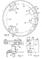
- the cited roller 33 engages with a camming path provided by tracks 34 formed on plates 35 which are peripherally profiled to match the path followed by the cam 5 and consequently by the various valving elements 2 during the various packaging steps.
- the cited plates 35 are arranged only at those areas where the roller 33 is to change its path, which change of path is implemented by a rotation of the upper body 6 with respect to the lower body 5.
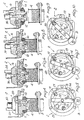
- a programmed actuation means for the cited upper body which comprises a roller 33 and track 34, enables the reaching of the various positions corresponding to the processing steps just described without any impacts, as was instead the case with conventional machines, and progressively, i.e. the progressive displacement, in the direction of rotation of the upper body with respect to the lower body, is effected through the roller moving along the camming path, which is located offcentered with respect to the axis of the rod 30, thereby any displacement of the camming path in the radial direction of translation of the various valving elements reflects in a relative rotational movement of the upper body 6 with respect to the lower body 5.
- transition to the various positions, corresponding to the various processing steps occurs through a first 90° rotation in one direction and three successive rotational movements in the opposite direction of the upper body 6 with respect to the lower body, which will correspond to a 90° overal rotation practically bringing the valving element back to its initial condition.
- the main connection channel 21 will communicate together the channel 10 and channel 11 connected to a vacuum source, thereby a vacuum is formed within the can.
- the roller 33 Upon completion of the vacuum forming step, the roller 33 is started along the track 34 of the plate as located at position B, thereby it causes the upper body to rotate relatively to the lower body, the rotational movement in question being approximately equal, in the present embodiment, to 47° in the opposite direction. In this position, the channel 10 is placed in communication with the channel 20 delivering the dressing liquid, which liquid is thus practically drawn into the can 4.
- the roller 33 After completing the dressing liquid filling step, which corresponds to the region included between B and C, the roller 33 contacts the track 34 of the plate 35, as occupying the position C, so that the upper body 6 will perform, under the action of the roller 33, a rotational movement, amounting to 18 degrees, again in the same direction of rotation as imparted to it at B, with respect to the lower body; in this position, as shown more clearly in Figure 7, the channel 10 still communicates to the dressing liquid delivery channel 20, whereas the auxiliary channel 12 of the lower body 5 communicates to the air suction channel 13 through the auxiliary connection channel 22.
- auxiliary connection channel 22 places the channel 12 in communication with the compressed air inlet channel 14 admitting compressed air into the channel 12 to remove any particles of dressing liquid still extant.
- the plate 3 carrying the cam is moved away from its corresponding valve element 2, the step of introducing the dressing liquid being over.
- the bleeding step is carried out subsequently to the vacuum breaking step and in the proximity of the cam A, so that any residual particles are allowed to fall into a fresh can to avoid fouling the machine and a waste of product.
- the vacuum breaking and bleeding steps occur in the region between D and A.
- the profile of the camming track 34 is such that in the transitions between the various processing steps, the upper body undergoes, relatively to the lower body, an initial rotation by 90° in one direction and three sucessive rotations in the opposite direction which amount to an overall rotation by 90°.
- the machine is equipped with a safety device, known per se, which inhibits the carrying out of the various processing steps where no can happens to be present.
- Said device comprises a movable cam 50 located at the start of the cam A which in the presence of a can will arrange itself as shown in Figure 12, whereas in the absence of a can will retracts as shown in Figure 13, thereby the roller 33 follows an outer path without interfering with the various cams and causing any relative rotations of the lower and upper bodies.
- actuating means comprising a roller 33 which engages with camming paths so implemented as to provide instantaneous rotational movements of the upper body with respect to the lower body in a continuous manner, that is without shocks, radically eliminates all of the aforesaid problems, in that no impacts are generated which in addition to an annoying noise would also bring about, as mentioned above, serious wear problems as well as problems of emission of metal dust in the environment air.
- the materials employed, if compatible with the intended use, and the dimensions and contingent shapes may be any ones suitable for the individual application.
Landscapes
- Engineering & Computer Science (AREA)
- Mechanical Engineering (AREA)
- Chemical & Material Sciences (AREA)
- Dispersion Chemistry (AREA)
- Basic Packing Technique (AREA)
- Vacuum Packaging (AREA)
Claims (6)
Applications Claiming Priority (2)
| Application Number | Priority Date | Filing Date | Title |
|---|---|---|---|
| IT2557380A IT1134035B (it) | 1980-10-24 | 1980-10-24 | Gruppo di introduzione del liquido di governo per colmatrici sottovuoto e simili |
| IT2557380 | 1980-10-24 |
Publications (2)
| Publication Number | Publication Date |
|---|---|
| EP0050754A1 EP0050754A1 (de) | 1982-05-05 |
| EP0050754B1 true EP0050754B1 (de) | 1986-04-09 |
Family
ID=11217133
Family Applications (1)
| Application Number | Title | Priority Date | Filing Date |
|---|---|---|---|
| EP19810107914 Expired EP0050754B1 (de) | 1980-10-24 | 1981-10-05 | Vorrichtung zur Flüssigkeitsabfüllung bei Vakuumverpackungen |
Country Status (5)
| Country | Link |
|---|---|
| US (1) | US4448227A (de) |
| EP (1) | EP0050754B1 (de) |
| DE (1) | DE3174322D1 (de) |
| ES (1) | ES507048A0 (de) |
| IT (1) | IT1134035B (de) |
Families Citing this family (4)
| Publication number | Priority date | Publication date | Assignee | Title |
|---|---|---|---|---|
| ES8404829A2 (es) * | 1983-05-27 | 1984-05-16 | Metalquimia Sa | Mejoras en la patente principal n 473.522 que se refiere a maquina perfeccionada dosificadora de masas carnicas |
| US6969396B2 (en) * | 2003-05-07 | 2005-11-29 | Scimed Life Systems, Inc. | Filter membrane with increased surface area |
| DE602006005421D1 (de) * | 2005-06-28 | 2009-04-16 | John Bean Technologies Corp | Ventil für Prevakuumfüller für partikelförmige Produkte |
| CN112937947A (zh) * | 2021-04-12 | 2021-06-11 | 河南黄河实业集团技术中心有限公司 | 一种负压式防滴漏加注机构 |
Family Cites Families (6)
| Publication number | Priority date | Publication date | Assignee | Title |
|---|---|---|---|---|
| US2359785A (en) * | 1940-04-27 | 1944-10-10 | American Can Co | Liquid filling apparatus |
| US2543788A (en) * | 1948-11-30 | 1951-03-06 | American Can Co | Filling head having air locked chamber for filling liquids into containers |
| US2903023A (en) * | 1956-11-13 | 1959-09-08 | Battinich Mitchell | Method and apparatus for filling cans and the like |
| US3321887A (en) * | 1964-07-08 | 1967-05-30 | M R M Company Inc | Method and apparatus for adding liquid fill to containers having solids therein |
| US3990487A (en) * | 1975-04-09 | 1976-11-09 | Atlas Pacific Engineering Company | Vacuum filler |
| US4369821A (en) * | 1981-03-30 | 1983-01-25 | Adolph Coors Company | Cam actuated filler valve |
-
1980
- 1980-10-24 IT IT2557380A patent/IT1134035B/it active
-
1981
- 1981-10-05 DE DE8181107914T patent/DE3174322D1/de not_active Expired
- 1981-10-05 EP EP19810107914 patent/EP0050754B1/de not_active Expired
- 1981-10-13 US US06/310,590 patent/US4448227A/en not_active Expired - Lifetime
- 1981-10-23 ES ES507048A patent/ES507048A0/es active Granted
Also Published As
| Publication number | Publication date |
|---|---|
| DE3174322D1 (en) | 1986-05-15 |
| ES8205689A1 (es) | 1982-08-16 |
| US4448227A (en) | 1984-05-15 |
| EP0050754A1 (de) | 1982-05-05 |
| IT8025573A0 (it) | 1980-10-24 |
| IT1134035B (it) | 1986-07-24 |
| ES507048A0 (es) | 1982-08-16 |
Similar Documents
| Publication | Publication Date | Title |
|---|---|---|
| US4024896A (en) | Washing device for rotary filling machine | |
| US3340668A (en) | Apparatus for and method of hermetically sealing a package | |
| EP0962420B1 (de) | Drehtischfüllmaschine zum Abfüllen von Flüssigkeiten in Behälter | |
| US3209676A (en) | Coffee dispensing | |
| EP0080774A2 (de) | Durch den Behälter betätigbarer Gegendruckfüllkopf | |
| EP0050754B1 (de) | Vorrichtung zur Flüssigkeitsabfüllung bei Vakuumverpackungen | |
| GB2154992A (en) | Filling head | |
| CN112693641B (zh) | 一种用于调料装袋封口的设备 | |
| US3333571A (en) | Apparatus for lining container closures | |
| US1504088A (en) | Process for sealing containers in vacuum | |
| EP0488215A1 (de) | Vorrichtung zum Befüllen von Behältern | |
| US4532971A (en) | High speed vacuum syruper | |
| US2315255A (en) | Can filling machine | |
| US2363248A (en) | Vacuum can seamer | |
| JPH04242592A (ja) | 容器特に瓶に液状充填物を充填する装置 | |
| US2536746A (en) | Filling valve | |
| JP2831170B2 (ja) | ロータリ充填機のバルブ洗浄装置 | |
| US2144634A (en) | Can closing machine | |
| JP3596042B2 (ja) | ガス置換装置を備えたキャッパ | |
| US4544005A (en) | Can detection and switch mechanism for can filling apparatus | |
| US2728946A (en) | Hydraulic apparatus for molding liners in jar closures | |
| US2107474A (en) | Receptacle cleaning and filling machine | |
| US762551A (en) | Automatic vacuumizing and double-seaming machine. | |
| US2698123A (en) | Apparatus for filling or partly filling containers | |
| CN220948722U (zh) | 一种人参鸡真空包装机 |
Legal Events
| Date | Code | Title | Description |
|---|---|---|---|
| PUAI | Public reference made under article 153(3) epc to a published international application that has entered the european phase |
Free format text: ORIGINAL CODE: 0009012 |
|
| AK | Designated contracting states |
Designated state(s): BE DE FR GB NL |
|
| 17P | Request for examination filed |
Effective date: 19821018 |
|
| GRAA | (expected) grant |
Free format text: ORIGINAL CODE: 0009210 |
|
| AK | Designated contracting states |
Kind code of ref document: B1 Designated state(s): BE DE FR GB NL |
|
| REF | Corresponds to: |
Ref document number: 3174322 Country of ref document: DE Date of ref document: 19860515 |
|
| ET | Fr: translation filed | ||
| PLBE | No opposition filed within time limit |
Free format text: ORIGINAL CODE: 0009261 |
|
| STAA | Information on the status of an ep patent application or granted ep patent |
Free format text: STATUS: NO OPPOSITION FILED WITHIN TIME LIMIT |
|
| 26N | No opposition filed | ||
| REG | Reference to a national code |
Ref country code: FR Ref legal event code: CL |
|
| PGFP | Annual fee paid to national office [announced via postgrant information from national office to epo] |
Ref country code: DE Payment date: 19980923 Year of fee payment: 18 |
|
| PGFP | Annual fee paid to national office [announced via postgrant information from national office to epo] |
Ref country code: FR Payment date: 19980930 Year of fee payment: 18 |
|
| PGFP | Annual fee paid to national office [announced via postgrant information from national office to epo] |
Ref country code: GB Payment date: 19981009 Year of fee payment: 18 |
|
| PGFP | Annual fee paid to national office [announced via postgrant information from national office to epo] |
Ref country code: BE Payment date: 19981021 Year of fee payment: 18 |
|
| PGFP | Annual fee paid to national office [announced via postgrant information from national office to epo] |
Ref country code: NL Payment date: 19981031 Year of fee payment: 18 |
|
| PG25 | Lapsed in a contracting state [announced via postgrant information from national office to epo] |
Ref country code: GB Free format text: LAPSE BECAUSE OF NON-PAYMENT OF DUE FEES Effective date: 19991005 |
|
| PG25 | Lapsed in a contracting state [announced via postgrant information from national office to epo] |
Ref country code: BE Free format text: LAPSE BECAUSE OF NON-PAYMENT OF DUE FEES Effective date: 19991031 |
|
| BERE | Be: lapsed |
Owner name: ZANICHELLI GIUSEPPE Effective date: 19991031 |
|
| PG25 | Lapsed in a contracting state [announced via postgrant information from national office to epo] |
Ref country code: NL Free format text: LAPSE BECAUSE OF NON-PAYMENT OF DUE FEES Effective date: 20000501 |
|
| GBPC | Gb: european patent ceased through non-payment of renewal fee |
Effective date: 19991005 |
|
| PG25 | Lapsed in a contracting state [announced via postgrant information from national office to epo] |
Ref country code: FR Free format text: LAPSE BECAUSE OF NON-PAYMENT OF DUE FEES Effective date: 20000630 |
|
| NLV4 | Nl: lapsed or anulled due to non-payment of the annual fee |
Effective date: 20000501 |
|
| PG25 | Lapsed in a contracting state [announced via postgrant information from national office to epo] |
Ref country code: DE Free format text: LAPSE BECAUSE OF NON-PAYMENT OF DUE FEES Effective date: 20000801 |
|
| REG | Reference to a national code |
Ref country code: FR Ref legal event code: ST |