EP0050488B1 - Ventilatoren - Google Patents
Ventilatoren Download PDFInfo
- Publication number
- EP0050488B1 EP0050488B1 EP81304827A EP81304827A EP0050488B1 EP 0050488 B1 EP0050488 B1 EP 0050488B1 EP 81304827 A EP81304827 A EP 81304827A EP 81304827 A EP81304827 A EP 81304827A EP 0050488 B1 EP0050488 B1 EP 0050488B1
- Authority
- EP
- European Patent Office
- Prior art keywords
- shutter
- ventilator
- windshield
- return
- wind
- Prior art date
- Legal status (The legal status is an assumption and is not a legal conclusion. Google has not performed a legal analysis and makes no representation as to the accuracy of the status listed.)
- Expired
Links
- 238000000605 extraction Methods 0.000 claims abstract description 26
- 238000007664 blowing Methods 0.000 claims description 11
- 230000005484 gravity Effects 0.000 claims description 8
- 238000009423 ventilation Methods 0.000 claims description 7
- 230000000694 effects Effects 0.000 abstract description 6
- 238000007599 discharging Methods 0.000 abstract description 3
- XLYOFNOQVPJJNP-UHFFFAOYSA-N water Substances O XLYOFNOQVPJJNP-UHFFFAOYSA-N 0.000 description 5
- 244000241796 Christia obcordata Species 0.000 description 1
- 238000009434 installation Methods 0.000 description 1
- 238000012423 maintenance Methods 0.000 description 1
- 239000000463 material Substances 0.000 description 1
- 238000007789 sealing Methods 0.000 description 1
Images
Classifications
-
- F—MECHANICAL ENGINEERING; LIGHTING; HEATING; WEAPONS; BLASTING
- F24—HEATING; RANGES; VENTILATING
- F24F—AIR-CONDITIONING; AIR-HUMIDIFICATION; VENTILATION; USE OF AIR CURRENTS FOR SCREENING
- F24F7/00—Ventilation
- F24F7/02—Roof ventilation
- F24F7/025—Roof ventilation with forced air circulation by means of a built-in ventilator
Definitions
- This invention relates to ventilators and is concerned with powered, direct discharge ventilators, that is to say, ventilators which do not have a weathering cowl.
- a self-weathering, non-return shutter assemblage is employed to close the exit from the extraction fan duct of the ventilator when the ventilator fan is not operating and thereby prevent weather entry through the ventilator and draught entering the building, as well as conserving heat in the building.
- a surrounding tubular windshield of matching cross-sectional shape is conventionally provided for example as described in U.S. Patent No. 2,668,491 or in our British Patent No. 1061188.
- a problem still arises under some conditions of roof mounting, however, in as far as the non-return shutters tend to open when the extraction fan is stationary and the non-return shutters are required to be closed, due to the action of wind blowing across the top of the windshield, sometimes in one particular direction.
- the conventional windshield hitherto provided is necessarily somewhat tall. This, in itself, is open to objection for aesthetic reasons in so far as a roof mounted ventilator is, preferably, of low height so as not to stand out unduly against the sky. Because of the height of the windshield, however, the "wind-over" effect of wind blowing across the top of the windshield and tending to lift the non-return shutters by suction, when the shutters are required to be closed, is considerably increased. It would be possible to lock non-return shutters closed and to provide for automatic unlocking of the non-return shutters when the extraction fan of the ventilator is started up and automatic locking of the shutters when the extraction fan is shut down. Such an arrangement would be complicated and expensive to provide however and also it would be subject to failure of the locking mechanism or the operating means for the locking mechanism.
- the present invention proposes to employ a wind effect.
- U.S. Patent No. 2,492,242 describes ventilating apparatus for a building having a wind controlled ventilating flap which is closed by the action of wind on a windward side of the ventilator to prevent air entering under a valve cap of the ventilator. Wind blowing through the ventilator and across the top of the valve cap then draws air from under the valve cap and out of the building through a ventilation opening having a corresponding wind controlled flap on the opposite side of the ventilator, the suction thereby created holding the windward flap closed.
- a powered, direct discharge ventilator comprising a base defining a ventilation opening, an extraction fan carried by the base, a self-weathering non-return shutter means for closing the ventilation opening when the extraction fan is not operating and a windshield carried from the base and surrounding the shutter means is characterised by a wind deflector or wind deflectors mounted so as to extend at least partially above the upper edge of the windshield when the ventilator is mounted in a horizontal, flat roof position to deflect wind blowing in at least one direction across the top of the windshield downwardly into the windshield to assist in holding the non-return shutter means closed when the extraction fan is not operating.
- the wind deflector or wind deflectors of the invention may deflect wind blowing in at least one general direction across the top of the windshield downwardly into the windshield onto the non-return shutter or shutters to hold the non-return shutter or shutters closed when the shutter or shutters are in their closed position.
- a ring-form wind deflector is conveniently provided, mounted above or in the top of the windshield to turn air blowing over the top of the windshield in any direction into the windshield in a generally downwardly directed stream.
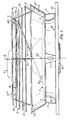
- the ventilator there shown is assumed to be mounted on a flat roof with the axis C of rotation of its extraction fan K extending vertically.
- the ventilator comprises a base B having a square base flange 10 intended to be flashed to the roof and a circular upstanding wall 11 defining a ventilation opening or throat 12 forming an extraction fan duct having a bell mouthed entry portion 13.
- Carried from the base flange 10 by bracket F is a shallow, inverted, frusto conical dish-form member D having a central, circular opening 15 in its floor.
- the upper edge portion of the wall 11 is received in the opening 15 with a small clearance so that a water drainage gap 16 is formed to allow rain water which enters the dish-form member D to drain out of the dish-form member onto the outside of the roof.
- the wall 11 penetrates upwardly into the dish-form member D to a small extent only, sufficient to prevent water entering the dish-form member D and running down onto the floor of the member, passing into the throat 12 of the ventilator and thence into the building being ventilated.
- the fan K is carried by radial arms A bolted to the base B by the same bolts and nuts as are used to secure the brackets F to the base B, the inner radial ends of the arms A being fixed to the fan motor casing.
- the fan impeller L is of the axial flow type and runs with a minimum clearance in an upper, cylindrical portion of the duct 12 of the ventilator.
- the upwardly discharging stream of air generated through the duct 12 of the ventilator prevents the entry of rain into the duct 12 of the ventilator and therefore into the building.
- a self-weathering non-return shutter S is provided to close the exit from the extraction fan duct 12.
- the non-return shutter S is of circular outline and is formed by a single disc or plate shaped like a hat in cross-section, the brim edge of which rests upon a number of circumferentially spaced apart rubber stops T carried in the floor of the member D such that the non-return shutter S is closely spaced above the top edge of the wall 11 and covers over and closes the opening defined by the wall 11 when the non-return shutter S is in its closed position as shown in full line in Figure 3.
- the non-return shutter S shelters the extraction fan duct 12 from the entry of rain and snow and the slope of the upper surface of the non-return shutter S drains rain water over the outside of the upper edge portion of the wall 11 into the dish-form member D, from which the water drains downwardly through the gap 16 previously described onto the outside of the roof.
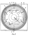
- a wire bird-guard or grid G is mounted on top of the member D.
- the grid is composed of an array of horizontally disposed circular wire hoops 14 of progressively smaller diameter held in vertically spaced apart relationship with respect to one another by upwardly extending interconnecting spring wires 17 having cranked lower end portions 17' sprung through individual holes in the wall of the dish-form member D and upper end portions 17" extending at first inwardly over the dish-form member D and then curving downwardly and terminating in short downwardly and outwardly extending portions 17"' which engage under the lower and radially inner edge of an annular, ring-form wind deflector W of circular outline to support the deflector co-axially with respect to the axis C.
- the deflector W has an undersurface WS which is inwardly and downwardly curved from its upper and radially outer edge W1 to its lower and radially inner edge W2 and acts to turn air blowing across the top of the member D downwardly into the hollow interior of the member D and onto the top surface of the non-return shutter S in a downwardly directed stream.
- the member D acts as a windshield to shelter the non-return shutter S against the action of wind to some extent when the non-return shutter is closed, the member D being, nevertheless, of an acceptably low height to meet aesthetic requirements.
- the member D by itself, is not capable of preventing unwanted opening of the non-return shutter S under all wind conditions.
- wind deflector W meets the problem because the downwardly directed stream of air created by the wind deflector W acts to assist in holding the non-return shutter S in its closed position to which it is always returned by its own weight when the extraction fan is shut down.
- wind entering the member D directly is prevented from lifting the shutter S and any "wind-over" suction effect on the shutter due to wind blowing across the top of the member D is eliminated by the action of the wind deflector W.
- the non-return shutter S is carried by a pair of hinge arms H to float up on the airstream discharged through the fan duct 12 when the extraction fan K is operating, to take up the position shown in chain-dotted outline in Figure 1 in which the upper surface of the brim portion of the non-return shutter S is pressed against the radially inner, lower edge W2 of the deflector W and the central "crown" portion of the shutter S is entered through the opening of the ring-form deflector W.
- the hinge arms H extend parallel to one another over their largest extent and define horizontally extending pivot axes N and N2 at their two ends respectively, the arms H being pivoted to the non-return shutter S on the side of its centre of gravity CG remote from their other ends, the other ends of the arms H being pivoted to a horizontal pivot rod P carried by an adjacent pair of the wires 17.
- a flexible strap R is provided (see Figure 1) tying the edge of the shutter S at a point midway between the hinge arms H on the side of the centre of gravity of the shutter remote from the hinge axis defined between the hinge arms and the shutter, to the bird-guard G.
- the dish-form member D is of upwardly divergent shape from its lower end to its upper end to allow air to be discharged upwardly and outwardly from the throat of the ventilator between the edge of the non-return shutter S and the upper edge of the member D when the non-return shutter S is in its open position.
- Figure 3 shows, on the right hand side, in chain-dotted outline, an alternative shape for the wall of the dish-form member D in which the member is upwardly divergent from its lower end towards its upper end, the upper end portion of the member being straight, i.e. cylindrical and vertically disposed in the present example.
- the gap 16 may be sealed with an elastomeric sealing ring, drainage holes being provided instead in the floor of the member D.
- drainage holes being provided instead in the floor of the member D.
- five such drainage holes are provided, one at each side of the stop T shown at the right hand side in Figure 1, one adjacent the stop T shown at the left hand side in Figure 1 and the other two at intermediate positions and respectively at opposite sides of the member D.
- the pair of drainage holes at the right hand side in Figure 1 accommodate the additional flow of rainwater when the ventilator is mounted on a pitched roof for example.
- the hinge rod P is positioned horizontally down slope towards the horizontal edge of the base 10, the ventilator then sloping from left to right in Figure 1.
- the centre of gravity CG of the shutter is positioned such that it always lies to that side of the plane of the axes N1, N2 adjacent the ventilator base 10.
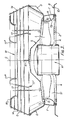
- the fan K has an "inside-out" motor of small vertical height so as to be generally within the base 10 of the fan, as shown in Figure 3 and a wire mesh safety guard Z is provided, covering the mouth of the entry portion 13 to the ventilation opening.
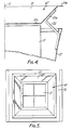
- the ventilator is generally as described in our British Patent No. 1061188 and has an upwardly divergent, square- sectioned windshield D' surrounding and sheltering a "four-square" non-return shutter assemblage one of the hinged shutters S' of which is illustrated swung open to a vertical position of maximum height in which its upper edge is at a level above the top of the windshield D'.
- the shutters S' do not normally swing open to this position when the extraction fan is started, but instead float up at some intermediate angle so as to assume an inclined position in which they are supported by the discharging air stream and, in fact, stops are usually provided preventing the non-return shutters S' opening to their maximum height.
- Mounted above the top of the windshield D' so as to extend inwardly of its upper edge, and conveniently above the maximum height of the shutters S' to facilitate maintenance work on the ventilator is an annular, ring-form wind deflector W' of square form outline composed of four air deflectors 21, one mounted along each of the four sides of the windshield D' by means of a pair of mounting brackets 22.
- Each deflector 21 has a plane, horizontally directed upper edge stiffening portion 21 b followed by a plane, downwardly and inwardly directed operative portion 21 a followed by a plane, horizontally directed lower edge stiffening portion 21 c and the deflectors abut one another at the four corners of the windshield D' so as to form a ring of generally square inverted frusto- pyramidal shape.
- the shutters S' In use of the ventilator, when the extraction fan (not shown) is not operating, the shutters S' normally assume their closed position weathering the exit from the extraction fan duct and preventing downdraughts into the building. Under high wind conditions, any tendency for wind blowing across the top of the windshield D' to create a suction effect or updraught inside the windshield, thereby lifting the shutters S', is prevented in as far as the wind striking one or more of the inclined portions 21 a of the deflectors 21 is directed downwardly into the inside of the windshield. The downwardly directed air stream may impinge upon the shutters S' positively to assist in holding them closed.
- the deflectors 21 it is not necessary for the deflectors 21 to abut one another at the corners of the windshield. Gaps could be left at the corners if desired. Furthermore, only one of the deflectors 21 or, say, an adjacent pair of the deflectors 21 only might be provided, to deal with a particular installation problem, caused by a prevailing wind.
- a circular wind deflector W is more conveniently used but a part circular wind deflector W could be used mounted above the windshield D or inside the top of the windshield D so as to extend above the top of the windshield to deal with a prevailing wind condition.
- the wind deflector or deflectors described may extend into the top of the windshield if desired.
- the non-return shutter S or shutters S' may be made of translucent material.
Landscapes
- Engineering & Computer Science (AREA)
- Chemical & Material Sciences (AREA)
- Combustion & Propulsion (AREA)
- Mechanical Engineering (AREA)
- General Engineering & Computer Science (AREA)
- Air-Conditioning For Vehicles (AREA)
- Air-Flow Control Members (AREA)
Claims (9)
Priority Applications (1)
| Application Number | Priority Date | Filing Date | Title |
|---|---|---|---|
| AT81304827T ATE7956T1 (de) | 1980-10-16 | 1981-10-16 | Ventilatoren. |
Applications Claiming Priority (2)
| Application Number | Priority Date | Filing Date | Title |
|---|---|---|---|
| GB8033414 | 1980-10-16 | ||
| GB8033414 | 1980-10-16 |
Publications (3)
| Publication Number | Publication Date |
|---|---|
| EP0050488A2 EP0050488A2 (de) | 1982-04-28 |
| EP0050488A3 EP0050488A3 (en) | 1982-09-08 |
| EP0050488B1 true EP0050488B1 (de) | 1984-06-13 |
Family
ID=10516715
Family Applications (1)
| Application Number | Title | Priority Date | Filing Date |
|---|---|---|---|
| EP81304827A Expired EP0050488B1 (de) | 1980-10-16 | 1981-10-16 | Ventilatoren |
Country Status (6)
| Country | Link |
|---|---|
| EP (1) | EP0050488B1 (de) |
| AT (1) | ATE7956T1 (de) |
| AU (1) | AU545302B2 (de) |
| DE (1) | DE3164215D1 (de) |
| NZ (1) | NZ198656A (de) |
| ZA (1) | ZA817088B (de) |
Families Citing this family (5)
| Publication number | Priority date | Publication date | Assignee | Title |
|---|---|---|---|---|
| AU576778B2 (en) * | 1983-08-26 | 1988-09-08 | Michele Young | Ventilator |
| GB2203232B (en) * | 1986-11-13 | 1991-01-16 | Colt Int Ltd | Improvements relating to ventilators |
| CN108426336B (zh) * | 2018-05-31 | 2023-09-29 | 深圳市万居科技股份有限公司 | 一种两用排风帽 |
| CN108626834B (zh) * | 2018-05-31 | 2023-09-29 | 深圳市万居科技股份有限公司 | 一种多用排风帽 |
| CN114831028B (zh) * | 2022-04-22 | 2023-09-01 | 扬州大学 | 一种便于通风的养殖装置 |
Family Cites Families (3)
| Publication number | Priority date | Publication date | Assignee | Title |
|---|---|---|---|---|
| US2492242A (en) * | 1943-08-28 | 1949-12-27 | James B Shaver | Ventilating apparatus |
| GB1061188A (en) * | 1964-04-13 | 1967-03-08 | Colt Ventilation & Heating Ltd | Improvements in or relating to ventilators |
| GB1151191A (en) * | 1965-05-19 | 1969-05-07 | Colt Ventilation & Heating Ltd | Improvements in or relating to Ventilators |
-
1981
- 1981-10-14 ZA ZA817088A patent/ZA817088B/xx unknown
- 1981-10-15 AU AU76381/81A patent/AU545302B2/en not_active Ceased
- 1981-10-15 NZ NZ198656A patent/NZ198656A/en unknown
- 1981-10-16 AT AT81304827T patent/ATE7956T1/de not_active IP Right Cessation
- 1981-10-16 DE DE8181304827T patent/DE3164215D1/de not_active Expired
- 1981-10-16 EP EP81304827A patent/EP0050488B1/de not_active Expired
Also Published As
| Publication number | Publication date |
|---|---|
| AU545302B2 (en) | 1985-07-11 |
| EP0050488A2 (de) | 1982-04-28 |
| DE3164215D1 (en) | 1984-07-19 |
| NZ198656A (en) | 1985-01-31 |
| AU7638181A (en) | 1982-04-22 |
| ZA817088B (en) | 1982-09-29 |
| EP0050488A3 (en) | 1982-09-08 |
| ATE7956T1 (de) | 1984-06-15 |
Similar Documents
| Publication | Publication Date | Title |
|---|---|---|
| EP0050488B1 (de) | Ventilatoren | |
| CN206984289U (zh) | 一种船舱用通风筒 | |
| US1766876A (en) | Ventilator for buildings | |
| GB2088042A (en) | Direct discharge ventilators | |
| US2641987A (en) | Ventilator | |
| US3412670A (en) | Roof ventilator | |
| GB2382128A (en) | Tilting ventilator hood | |
| US2854916A (en) | Exhauster ventilator | |
| US985148A (en) | Ventilator. | |
| KR200449441Y1 (ko) | 루프팬 환기장치 | |
| EP0273563B1 (de) | Schnappriegel für den Abschlussdeckel eines Lüfters | |
| US2100801A (en) | Air-flow ventilator | |
| US2823599A (en) | Ventilator | |
| CN113280429B (zh) | 一种绿色建筑用室内通风调节智能控制系统 | |
| US3366030A (en) | Roof mounted ventilator | |
| US3078781A (en) | Ventilator | |
| US2163077A (en) | Ventilator | |
| CS235535B2 (cs) | Ventilátor | |
| JP2003096988A (ja) | 換気天窓装置 | |
| KR101066785B1 (ko) | 비닐하우스용 배기장치 | |
| NO140118B (no) | Anordning ved ventilatorer. | |
| KR101623921B1 (ko) | 지붕 벤틸레이터 | |
| KR200194375Y1 (ko) | 승강개폐판을 구비한 환풍기 | |
| AU3441302A (en) | Tilting hood ventilator | |
| US7025670B1 (en) | Rotatable vent |
Legal Events
| Date | Code | Title | Description |
|---|---|---|---|
| PUAI | Public reference made under article 153(3) epc to a published international application that has entered the european phase |
Free format text: ORIGINAL CODE: 0009012 |
|
| AK | Designated contracting states |
Designated state(s): AT BE CH DE FR LU NL SE |
|
| PUAL | Search report despatched |
Free format text: ORIGINAL CODE: 0009013 |
|
| AK | Designated contracting states |
Designated state(s): AT BE CH DE FR LU NL SE |
|
| 17P | Request for examination filed |
Effective date: 19820810 |
|
| GRAA | (expected) grant |
Free format text: ORIGINAL CODE: 0009210 |
|
| AK | Designated contracting states |
Designated state(s): AT BE CH DE FR LI LU NL SE |
|
| REF | Corresponds to: |
Ref document number: 7956 Country of ref document: AT Date of ref document: 19840615 Kind code of ref document: T |
|
| REF | Corresponds to: |
Ref document number: 3164215 Country of ref document: DE Date of ref document: 19840719 |
|
| ET | Fr: translation filed | ||
| PGFP | Annual fee paid to national office [announced via postgrant information from national office to epo] |
Ref country code: FR Payment date: 19841012 Year of fee payment: 4 |
|
| PGFP | Annual fee paid to national office [announced via postgrant information from national office to epo] |
Ref country code: CH Payment date: 19841025 Year of fee payment: 4 |
|
| PG25 | Lapsed in a contracting state [announced via postgrant information from national office to epo] |
Ref country code: LU Free format text: LAPSE BECAUSE OF NON-PAYMENT OF DUE FEES Effective date: 19841031 |
|
| PGFP | Annual fee paid to national office [announced via postgrant information from national office to epo] |
Ref country code: DE Payment date: 19841109 Year of fee payment: 4 |
|
| PGFP | Annual fee paid to national office [announced via postgrant information from national office to epo] |
Ref country code: SE Payment date: 19841231 Year of fee payment: 4 Ref country code: BE Payment date: 19841231 Year of fee payment: 4 |
|
| PLBE | No opposition filed within time limit |
Free format text: ORIGINAL CODE: 0009261 |
|
| STAA | Information on the status of an ep patent application or granted ep patent |
Free format text: STATUS: NO OPPOSITION FILED WITHIN TIME LIMIT |
|
| 26N | No opposition filed | ||
| PGFP | Annual fee paid to national office [announced via postgrant information from national office to epo] |
Ref country code: NL Payment date: 19851031 Year of fee payment: 5 Ref country code: AT Payment date: 19851031 Year of fee payment: 5 |
|
| PG25 | Lapsed in a contracting state [announced via postgrant information from national office to epo] |
Ref country code: AT Effective date: 19861016 |
|
| PG25 | Lapsed in a contracting state [announced via postgrant information from national office to epo] |
Ref country code: SE Effective date: 19861017 |
|
| PG25 | Lapsed in a contracting state [announced via postgrant information from national office to epo] |
Ref country code: LI Effective date: 19861031 Ref country code: CH Effective date: 19861031 Ref country code: BE Effective date: 19861031 |
|
| BERE | Be: lapsed |
Owner name: COLT INTERNATIONAL HOLDINGS A.G. Effective date: 19861031 |
|
| PG25 | Lapsed in a contracting state [announced via postgrant information from national office to epo] |
Ref country code: NL Effective date: 19870501 |
|
| NLV4 | Nl: lapsed or anulled due to non-payment of the annual fee | ||
| PG25 | Lapsed in a contracting state [announced via postgrant information from national office to epo] |
Ref country code: FR Free format text: LAPSE BECAUSE OF NON-PAYMENT OF DUE FEES Effective date: 19870630 |
|
| REG | Reference to a national code |
Ref country code: CH Ref legal event code: PL |
|
| PG25 | Lapsed in a contracting state [announced via postgrant information from national office to epo] |
Ref country code: DE Effective date: 19870701 |
|
| REG | Reference to a national code |
Ref country code: FR Ref legal event code: ST |
|
| EUG | Se: european patent has lapsed |
Ref document number: 81304827.9 Effective date: 19870812 |