EP0050060B1 - Bilderzeugungssystem mit gleichzeitiger mehrfacher Aussendung - Google Patents
Bilderzeugungssystem mit gleichzeitiger mehrfacher Aussendung Download PDFInfo
- Publication number
- EP0050060B1 EP0050060B1 EP81401463A EP81401463A EP0050060B1 EP 0050060 B1 EP0050060 B1 EP 0050060B1 EP 81401463 A EP81401463 A EP 81401463A EP 81401463 A EP81401463 A EP 81401463A EP 0050060 B1 EP0050060 B1 EP 0050060B1
- Authority
- EP
- European Patent Office
- Prior art keywords
- signals
- path
- duration
- signal
- reception
- Prior art date
- Legal status (The legal status is an assumption and is not a legal conclusion. Google has not performed a legal analysis and makes no representation as to the accuracy of the status listed.)
- Expired
Links
Images


Classifications
-
- G—PHYSICS
- G01—MEASURING; TESTING
- G01S—RADIO DIRECTION-FINDING; RADIO NAVIGATION; DETERMINING DISTANCE OR VELOCITY BY USE OF RADIO WAVES; LOCATING OR PRESENCE-DETECTING BY USE OF THE REFLECTION OR RERADIATION OF RADIO WAVES; ANALOGOUS ARRANGEMENTS USING OTHER WAVES
- G01S7/00—Details of systems according to groups G01S13/00, G01S15/00, G01S17/00
- G01S7/52—Details of systems according to groups G01S13/00, G01S15/00, G01S17/00 of systems according to group G01S15/00
- G01S7/52017—Details of systems according to groups G01S13/00, G01S15/00, G01S17/00 of systems according to group G01S15/00 particularly adapted to short-range imaging
- G01S7/52085—Details related to the ultrasound signal acquisition, e.g. scan sequences
- G01S7/5209—Details related to the ultrasound signal acquisition, e.g. scan sequences using multibeam transmission
- G01S7/52093—Details related to the ultrasound signal acquisition, e.g. scan sequences using multibeam transmission using coded signals
-
- G—PHYSICS
- G01—MEASURING; TESTING
- G01S—RADIO DIRECTION-FINDING; RADIO NAVIGATION; DETERMINING DISTANCE OR VELOCITY BY USE OF RADIO WAVES; LOCATING OR PRESENCE-DETECTING BY USE OF THE REFLECTION OR RERADIATION OF RADIO WAVES; ANALOGOUS ARRANGEMENTS USING OTHER WAVES
- G01S15/00—Systems using the reflection or reradiation of acoustic waves, e.g. sonar systems
- G01S15/88—Sonar systems specially adapted for specific applications
- G01S15/89—Sonar systems specially adapted for specific applications for mapping or imaging
- G01S15/8906—Short-range imaging systems; Acoustic microscope systems using pulse-echo techniques
- G01S15/8959—Short-range imaging systems; Acoustic microscope systems using pulse-echo techniques using coded signals for correlation purposes
-
- G—PHYSICS
- G01—MEASURING; TESTING
- G01S—RADIO DIRECTION-FINDING; RADIO NAVIGATION; DETERMINING DISTANCE OR VELOCITY BY USE OF RADIO WAVES; LOCATING OR PRESENCE-DETECTING BY USE OF THE REFLECTION OR RERADIATION OF RADIO WAVES; ANALOGOUS ARRANGEMENTS USING OTHER WAVES
- G01S7/00—Details of systems according to groups G01S13/00, G01S15/00, G01S17/00
- G01S7/52—Details of systems according to groups G01S13/00, G01S15/00, G01S17/00 of systems according to group G01S15/00
- G01S7/52017—Details of systems according to groups G01S13/00, G01S15/00, G01S17/00 of systems according to group G01S15/00 particularly adapted to short-range imaging
- G01S7/52085—Details related to the ultrasound signal acquisition, e.g. scan sequences
- G01S7/5209—Details related to the ultrasound signal acquisition, e.g. scan sequences using multibeam transmission
-
- G—PHYSICS
- G10—MUSICAL INSTRUMENTS; ACOUSTICS
- G10K—SOUND-PRODUCING DEVICES; METHODS OR DEVICES FOR PROTECTING AGAINST, OR FOR DAMPING, NOISE OR OTHER ACOUSTIC WAVES IN GENERAL; ACOUSTICS NOT OTHERWISE PROVIDED FOR
- G10K11/00—Methods or devices for transmitting, conducting or directing sound in general; Methods or devices for protecting against, or for damping, noise or other acoustic waves in general
- G10K11/18—Methods or devices for transmitting, conducting or directing sound
- G10K11/26—Sound-focusing or directing, e.g. scanning
- G10K11/34—Sound-focusing or directing, e.g. scanning using electrical steering of transducer arrays, e.g. beam steering
- G10K11/341—Circuits therefor
Definitions
- the object of the present invention is to improve radar or sonar type echo detection systems, making it possible to provide an image of the surrounding space in real time.
- the device according to the invention applies more particularly to high definition sonar devices by channel formation, such as acoustic cameras and target classification systems in underwater technique, the imaging being carried out in frontal vision.
- the invention also applies to medical acoustic imaging and non-destructive tests.
- Radar or sonar type systems generally consist of at least one transmitter whose transmitted signals "light up" the angular field to be observed and a receiving antenna whose received signals are used to form a set of angular channels covering this field. Each channel formed corresponds to a distribution of the energy received in space, whose angular width of the main lobe at half the power defines the angular resolution.
- the signals transmitted around this frequency f, by the transducers of the transmitting antenna, are delayed or phase shifted with respect to each other, to form channels in directions making a constant angle with the direction of the antenna d 'program.
- the emission channels are formed sequentially over time.
- This device for forming fine angular channels has the disadvantage of a low information rate, since it is necessary to transmit on all the transmitters as many times as there are transmission channels.
- the receiving antenna in this arrangement is formed by several alignments of transducers. Processing of the set of signals received by the transducer makes it possible to form fine angular paths in two directions. If the number of channels to be formed is large, which is generally the case when it is desired to obtain a fine angular resolution, the number of receivers is large and the volume of electrical circuits also.
- Keating uses general-purpose computer 52 or 68 as channel training means, the operation of which is not particularly described and which it is doubtful can be fast enough to give a complete picture in good time.
- the invention proposes to linearly group the emission transducers along a first axis, and the reception transducers linearly along a second axis perpendicular to the first.
- the means for processing the reception signals form a first set of channels corresponding to planes distributed in a fan along a first coordinate 6, and in each of these planes a second set of channels corresponding to directions distributed in a fan in this plane according to a second coordinate ⁇ .
- a space analysis is thus obtained according to a beam of channels regularly distributed along the two coordinates 6 and ⁇ from an antenna formed by two alignments of transducers arranged in a cross.
- the device according to the invention consists of a transmitting antenna composed of M transmitting transducers E 1 , E 2 , ..., E i , ..., E M and a receiving antenna composed of N reception transducers H 1 , H 2 , ..., H i , ..., H N (fig. 1).
- This figure shows a linear transmitting antenna in a direction Oz and a linear receiving antenna in the perpendicular direction Ox.
- the transmit-receive antenna may be composed of a set of transducers, a number of which are capable of having the transmit functions, while others are capable of having the receive functions. . It is possible to have transducers having both transmission and reception functions. These transducers adequately sample the space, so that channels can be formed both on transmission and on reception.
- the distribution of these transducers can be arbitrary provided that their coordinates are known. The most widely used are, however, trirectangular, spherical, cylindrical, circular, planar or conformal distributions.
- the transmission-reception device of FIG. 1 makes it possible to form reception channels in a direction ⁇ 1 and transmission channels in an average direction ⁇ 2 .
- the lines ⁇ 1 and ⁇ 2 respectively form the directions 0 and ⁇ with the directions Ox and Oz.
- This figure shows the traces D 1 and D 2 of the limit curves of the 3dB attenuation diagrams of the reception channels.
- D 3 and D 4 are the traces of the limit curves of the emission channels for the 3dB attenuation diagrams. If L is the length of the two antennas, the widths of these channels are equal to ⁇ / L.
- the principle of formation of transmission channels, on reception according to the invention generally consists in using omnidirectional transmitters E 1 to E M , distributed in space according to a certain geometry, and emitting M separable signals.
- E 1 to E M omnidirectional transmitters
- E M omnidirectional transmitters
- ⁇ and ⁇ of space propagates a signal S ( ⁇ , ⁇ ) formed by the sum in amplitude and phase of the signals emitted in this direction.
- This signal S ( ⁇ , ⁇ ) depends on the direction as well as on the geometric position of the transmitters.
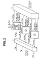
- the general block diagram of the system is represented in FIG. 2.
- Each channel signal such that V k ( ⁇ k ) is sent to a processing unit 2 which performs the filtering adapted to the Q signals S i, k ( ⁇ i , ⁇ k ) forming Q channels. In the figure, this operation has been symbolized by the sign ⁇ .
- P x Q channel signals W i, k ( ⁇ i , ⁇ k ) which are then used in 3.
- the processing unit 1 performing the formation of the reception channels V k can be implemented according to two main techniques known in relation to the type of reception antenna and the frequency band B of the signals H i received.
- the second technique applies when the receiving antenna is formed of a linear array of equidistant sensors and when the antenna depth p is less than C / B.
- the processing means implemented on the signals received by all the sensors are a multiplexing of the signals received in a small time interval before 1 / B providing a sequence of the signals in series in time, followed by a digital or analog device which performs the Fourier transform of this sequence.
- a digital or analog device which performs the Fourier transform of this sequence.
- the processing unit 2 performing the formation of the transmission channels by adapted filtering can be implemented: either by processing each reception channel signal V k ( ⁇ k ) in parallel in Q filters adapted to the Q signals S i, k ( ⁇ i , ⁇ k ) i varying from 1 to Q, either by processing each channel signal V k ( ⁇ k ) of reception sequentially by convolving it with the Q copies of the signals S i, k ( ⁇ i , ⁇ k ) returned in time.
- the preferred embodiment of the invention comprises a transmitting antenna formed by a linear array of transmitters and a receiving antenna formed by a linear array of equidistant sensors.
- the two antennas are placed orthogonally to each other as shown in Figure 1.
- the transmission band B and the antenna depth p are chosen to implement the formation of the reception channels V k ( ⁇ k ) by the technique using a Fourier transform.
- this Fourier transform is carried out analogically by the use of elastic wave dispersive filters.
- the formation of the transmission channels it is obtained by sequential correlation of the reception channel signals with the signals S i , k obtained by their convolution with the signals S i , k returned in time.
- this convolution is carried out analogically by the use of an elastic wave convolver. This preferred embodiment has the advantage of allowing high operating speeds and of providing a reduced bulk.
- the transmitting antenna is formed of a linear array of M transmitters receiving from a generator the coded signals Ci to C M.
- the M broadcasts are produced simultaneously, their duration T and their band b.
- the types of emissions possible are those described above.
- the central frequency of these transmissions is f o and the total band occupied is B.
- the signals are received by a reception antenna formed by a linear array of N equidistant sensors H 1 to H N , for example hydrophones in the case of a sonar. These signals are demodulated by N circuits 60.1, 60.2, ... 60.N represented in FIG. 6. Each signal received by a sensor such that H j is multiplied in M 1 and M 2 by the two signals cos (2 ⁇ f o t ) and sin (2 ⁇ rf o t) in phase quadrature, supplied by a local oscillator.
- the signals H j.1 and H j.2 are thus obtained after low-pass filtering at 161 and 167 with a cut-off frequency close to B / 2, these two signals being called real component and imaginary component.
- Two synchronous multiplexers 61.1 and 61.2 multiplex the real and imaginary components of the N demodulated signals H j.1 and H j.2 .
- These multiplexer circuits are controlled by a clock signal H of period T H , the value of which is chosen so that N signals by a sensor such as H j are multiplexed in a time interval NT H , small in front of 1 / B.
- the signal of each hydrophone is sampled at frequency B, and a signal composed of groups of signals of duration NT H separated by a time 1 / B is obtained at the output of each multiplexer circuit.
- These two signals 62.1 and 62.2 obtained at the output of two multiplexers 61.1 and 61.2 are modulated in a circuit 62 shown in FIG. 7.
- the multiplier circuits M 4 and M 3 are multiplied in the multiplier circuits M 4 and M 3 by the two signals cos (2 ⁇ f z t) and sin (2 ⁇ f z t) supplied by a local oscillator, then the two signals obtained are added in an adder circuit 70.1 and the signal obtained is filtered in a filtering circuit 70.2 bandpass of width B z and central frequency F z .
- the band B z is a function of the frequency of multiplexing of the signals such as H j.1 and H j.2 and the central frequency f z is chosen to be equal to approximately three times the band B z .
- This output signal 62.3 from the modulator 62 is sent to an analog Fourier transformer 63 using elastic wave dispersive filters and for which two embodiments are possible.
- the first embodiment shown in FIG. 8 is an assembly called MCM (multiplication-convolution-multiplication).
- the input signal 62.3 is premultiplied in a multiplier circuit 82 by a signal called a “ramp” modulated linearly in frequency, the band of which is B z and the duration T z .
- This signal is obtained by sending a very short pulse to the input of a dispersil filter 81.
- the signal at the output of the multiplier 82 is convolved in a dispersive filter 83 whose band is 2B z and the duration 2T z .
- the signal obtained is post-multiplied in a circuit 84 by a ramp signal identical to the previous one generated by the dispersive filter 85.
- the Fourier transform signal of the input signal 62.3 is obtained at the output 64 of the multiplier 84.
- the second embodiment shown in FIG. 9 is a so-called CMC assembly (convolution-multiplier-convolution).
- the input signal 62.3 is first convolved in a dispersive filter 91 of band B z and of duration T z , then multiplied in 92 by a ramp signal supplied by a dispersive filter 93 of band 2B z and of duration 2T z .
- the signal obtained at the output of the multiplier 92 is then sent to a dispersive filter 94 identical to the filter 91.
- the Fourier transformed signal of the signal 62.3 is obtained at the output of the dispersive filter 94 at 64.
- the transformed Fourier signal 64 is then demodulated in circuit 164, FIG. 3, of structure identical to circuits 60 in which the signals in phase quadrature are cos (2 ⁇ f z t) and sin (2 ⁇ f z t).
- the two components obtained are converted to digital by the two converters 65.1 and 65.2 under control of the clock H and stored separately in the digital memories 66.1 and 66.2, these memories being for example of the random access type (RAM).
- Each group of channel signals such as 41.i is stored in memory as a line.
- the signals thus stored are read sequentially column by column at the rate 1 / B.
- the memory is for example split into two blocks which are used alternately: filling of a block line by line and simultaneously reading and the other block column by column, then switching of the blocks.
- the transmitting antenna being formed of a linear array of transmitters, the signals S i, k ( ⁇ , ⁇ k ), defined above depend only on the directions defined by the angle ⁇ i with the transmitting antenna , and can therefore be expressed according to S i ( ⁇ i ).
- the system includes digital memories 70.1 and 70.2, for example of the RAM type, which contain the demodulated and time-inverted copies of the Q signals S i ( ⁇ i ) in the form of the real and imaginary components. These Q signals are stored over the duration T at the frequency B and therefore comprise K samples.
- V k ( ⁇ k ) and S i ( ⁇ i ) are read in synchronism respectively in the memories 66.1, 66.2 and 70.1 and 70.2 under control of the clock H. Their duration is identical and equal to KT H.
- the same channel signal V k ( ⁇ k ) is read Q times in synchronism with the Q signals S 1 to S Q.
- the figures 5-a and 5-b respectively represent the signals of channels V k and the signals Si as a function of time. Each signal is composed of Q groups of KT H signals in series over time.
- the reading rate 1 / B of the signals V k or Si must therefore be greater than or at least equal to QKTH.
- the output signals 66.6, 66.7 and 70.6, 70.7 of memories 66 and 70 as represented on the figures 5-a and 5-b, are converted into analog by the converters 67.1, 67.2, modulated by the two circuits 68.1 and 68.2 and applied to the two inputs of a convolver device 69 using the propagation of elastic waves.
- the acoustic surface wave device 100 known elsewhere (FIG. 10) is provided with two electrodes 102 and 103 of length L i .
- the signals to be convoluted F (t) e jwt and G (t) e jwt , where w is the angular frequency of the carrier, are applied to comb transducers T 1 and T 2 placed at the two ends of the device 100. Consequently non-linear effects, the convoluted signal R (t) is collected between the two electrodes such that: where C is a constant.
- the convolutor output signal is represented on the figure 5-c. It is composed per channel V k of Q correlation signals separated by a time equal to KT H and of central frequency 2f z which relate to the signals of channels formed along Q directions ⁇ i for the direction ⁇ k or W 1 , k at W Q , k . These signals leave the convolver with a time offset equal to the duration KT H of the input signals.
- the convolutor output signal is then demodulated in circuit 71 identical to circuit 60 shown in Figure 6 in which the frequency f o is replaced by the frequency 2f z supplied by a local oscillator, then converted to digital by the converters 72.1 and 72.2 for be stored in memory or used.
- These signals provide a two-dimensional image ⁇ , ⁇ during a duration T.
- the memories 70.1 and 70.2 must store the copies of the Q x N signals S i, k , ( ⁇ i , ⁇ k ) and their size is greater. Whenever a channel signal V k ( ⁇ k ) is read from memories 66.1 and 66.2, the corresponding Q signals S 1, k ( ⁇ i , ⁇ k to S Q, k ( ⁇ Q , ⁇ k ) are read in memories 70.1 and 70.2.
- the number of channels Q is taken equal to N.
- the condition QBTT H ⁇ 1 / B is fulfilled.
- the duration of the signals at the input and at the output of the Fourier transformer as well as at the input of the convolutor is equal to 2.5 ⁇ s.
- FIG. 11 An alternative embodiment is shown in Figure 11. It implements the parallel processing mentioned above.
- the output signal for each channel such as V k ( ⁇ k ) from the modulator 68.2 to 68.3 (fig. 3) is sent simultaneously to the input of Q adapted filters 110.1k, 110.2k, ... 110.Qk to the signals S 1, K to S Q, k .
- These filters are for example produced using the propagation of elastic waves, the duration of the impulse response of each filter corresponds to the duration T and each filter results in processing equivalent to a convolution and the output signals of each suitable filter have a maximum representative of the signal from a direction ⁇ i , 8 k .
- the set of Q filters 110.1k to 110.Qk remains identical for the N channel signals V k ( ⁇ K ) and can be multiplexed .
Landscapes
- Engineering & Computer Science (AREA)
- Physics & Mathematics (AREA)
- Radar, Positioning & Navigation (AREA)
- Remote Sensing (AREA)
- Acoustics & Sound (AREA)
- Computer Networks & Wireless Communication (AREA)
- General Physics & Mathematics (AREA)
- Multimedia (AREA)
- Measurement Of Velocity Or Position Using Acoustic Or Ultrasonic Waves (AREA)
- Closed-Circuit Television Systems (AREA)
- Studio Devices (AREA)
Claims (9)
Applications Claiming Priority (2)
| Application Number | Priority Date | Filing Date | Title |
|---|---|---|---|
| FR8021681A FR2492109B1 (fr) | 1980-10-10 | 1980-10-10 | Systeme d'imagerie a emissions multiples et simultanees |
| FR8021681 | 1980-10-10 |
Publications (2)
| Publication Number | Publication Date |
|---|---|
| EP0050060A1 EP0050060A1 (de) | 1982-04-21 |
| EP0050060B1 true EP0050060B1 (de) | 1986-05-07 |
Family
ID=9246746
Family Applications (1)
| Application Number | Title | Priority Date | Filing Date |
|---|---|---|---|
| EP81401463A Expired EP0050060B1 (de) | 1980-10-10 | 1981-09-18 | Bilderzeugungssystem mit gleichzeitiger mehrfacher Aussendung |
Country Status (8)
| Country | Link |
|---|---|
| US (1) | US4456982A (de) |
| EP (1) | EP0050060B1 (de) |
| AU (1) | AU547216B2 (de) |
| CA (1) | CA1188404A (de) |
| DE (1) | DE3174568D1 (de) |
| DK (1) | DK449181A (de) |
| FR (1) | FR2492109B1 (de) |
| NO (1) | NO813419L (de) |
Families Citing this family (42)
| Publication number | Priority date | Publication date | Assignee | Title |
|---|---|---|---|---|
| FR2594274B1 (fr) * | 1982-08-27 | 1988-08-26 | Thomson Csf | Procede de compression d'impulsions par codage de l'espace et son application a un radar |
| FR2540636A1 (fr) * | 1983-02-08 | 1984-08-10 | Thomson Csf | Formation de voies sonar par des dispositifs a transfert de charges |
| DE3335421A1 (de) * | 1983-09-29 | 1985-04-18 | Siemens AG, 1000 Berlin und 8000 München | Verfahren zur signalauswertung von ultraschall-echosignalen, wie sie bei verwendung eines ultraschall-sensors an einem roboterarm auftreten |
| US4747411A (en) * | 1984-03-28 | 1988-05-31 | National Biochemical Research Foundation | Three-dimensional imaging system |
| US4799177A (en) * | 1985-12-31 | 1989-01-17 | The Boeing Company | Ultrasonic instrumentation for examination of variable-thickness objects |
| US4799167A (en) * | 1985-12-31 | 1989-01-17 | The Boeing Company | Ultrasonic 64 channel inspection system with multigate/multimode selection software configurability |
| US4855961A (en) * | 1986-07-31 | 1989-08-08 | Woods Hole Oceanographic Institute | Imaging apparatus |
| US4847817A (en) * | 1987-12-31 | 1989-07-11 | The United States Of America As Represented By The Secretary Of The Navy | Broadband sonar signal processor and target recognition system |
| US5063780A (en) * | 1990-02-15 | 1991-11-12 | General Electric Company | Ultrasonic dimensional and flaw inspection of thin-walled tubular elements |
| US5213105A (en) * | 1990-12-04 | 1993-05-25 | Research Corporation Technologies, Inc. | Frequency domain optical imaging using diffusion of intensity modulated radiation |
| US5142649A (en) * | 1991-08-07 | 1992-08-25 | General Electric Company | Ultrasonic imaging system with multiple, dynamically focused transmit beams |
| FR2696573B1 (fr) * | 1992-10-02 | 1996-08-30 | Univ Paris | Procede et dispositif d'examen acoustique a retournement temporel. |
| US5598206A (en) * | 1994-04-11 | 1997-01-28 | Bullis; James K. | Beamformed television |
| JPH10507936A (ja) | 1994-08-05 | 1998-08-04 | アキュソン コーポレイション | 送信ビーム生成器システムのための方法及び装置 |
| US5675554A (en) * | 1994-08-05 | 1997-10-07 | Acuson Corporation | Method and apparatus for transmit beamformer |
| US5546808A (en) * | 1994-09-06 | 1996-08-20 | Harris Instrument Corporation | Apparatus and method for binocular measurement system |
| US6005827A (en) | 1995-03-02 | 1999-12-21 | Acuson Corporation | Ultrasonic harmonic imaging system and method |
| US5608690A (en) * | 1995-03-02 | 1997-03-04 | Acuson Corporation | Transmit beamformer with frequency dependent focus |
| US5678554A (en) * | 1996-07-02 | 1997-10-21 | Acuson Corporation | Ultrasound transducer for multiple focusing and method for manufacture thereof |
| US6027448A (en) * | 1995-03-02 | 2000-02-22 | Acuson Corporation | Ultrasonic transducer and method for harmonic imaging |
| US6009046A (en) * | 1995-03-02 | 1999-12-28 | Acuson Corporation | Ultrasonic harmonic imaging system and method |
| US6104671A (en) * | 1996-03-28 | 2000-08-15 | Reed W. Hoyt | Apparatus and method for measuring the relative velocity and true distance between two objects |
| US5867274A (en) | 1997-02-14 | 1999-02-02 | Harris Instrument Corporation | System for the measurement of the cut length of moving articles |
| US5891037A (en) * | 1997-12-18 | 1999-04-06 | Acuson Corporation | Ultrasonic Doppler imaging system with frequency dependent focus |
| GB9901306D0 (en) | 1999-01-21 | 1999-03-10 | Smythe David | 3D/4D ultrasound imaging system |
| US6213947B1 (en) | 1999-03-31 | 2001-04-10 | Acuson Corporation | Medical diagnostic ultrasonic imaging system using coded transmit pulses |
| US6179780B1 (en) * | 1999-08-06 | 2001-01-30 | Acuson Corporation | Method and apparatus for medical diagnostic ultrasound real-time 3-D transmitting and imaging |
| US6241674B1 (en) | 1999-03-31 | 2001-06-05 | Acuson Corporation | Medical ultrasound diagnostic imaging method and system with nonlinear phase modulation pulse compression |
| DE10008699C1 (de) * | 2000-02-24 | 2001-05-23 | Daimler Chrysler Ag | Verfahren und Vorrichtung zur Analog-Digital-Wandlung eines Signals |
| JP4812048B2 (ja) * | 2000-05-09 | 2011-11-09 | 株式会社日立メディコ | 超音波診断装置 |
| DE10028593C1 (de) * | 2000-06-14 | 2001-10-18 | Daimler Chrysler Ag | Verfahren und Vorrichtung zur Digital-Analog-Wandlung eines Signals |
| JP2002336246A (ja) * | 2001-05-14 | 2002-11-26 | Fuji Photo Film Co Ltd | 超音波撮像方法及び超音波撮像装置 |
| US6695778B2 (en) | 2002-07-03 | 2004-02-24 | Aitech, Inc. | Methods and systems for construction of ultrasound images |
| US6987707B2 (en) * | 2002-11-12 | 2006-01-17 | General Dynamics Advanced Information Systems, Inc. | Method and system for in-air ultrasonic acoustical detection and characterization |
| FR2853075B1 (fr) * | 2003-03-24 | 2005-06-10 | Centre Nat Rech Scient | Procede pour determiner des reponses impulsionnelles d'un milieu visa-vis de la transmission d'ondes entre differents points |
| US7375675B2 (en) * | 2004-04-05 | 2008-05-20 | Sri International | Method and system for multiple target class data recording, processing and display for over-the-horizon radar |
| DE102007045103A1 (de) * | 2007-09-20 | 2009-04-02 | Loeffler Technology Gmbh | Verfahren und Vorrichtung zur synthetischen Bildgebung |
| GB0916162D0 (en) * | 2009-09-15 | 2009-10-28 | Oceanscan Ltd | Scanning apparatus and method |
| DE102010006334A1 (de) * | 2010-01-29 | 2011-08-04 | pro-micron GmbH & Co. KG, 87600 | System und Verfahren zur Störunterdrückung bei frequenzmodulierten Radarsystemen |
| FR2977671B1 (fr) * | 2011-07-08 | 2013-11-29 | 01Db Metravib | Procede et dispositif pour controler des structures par retournement temporel |
| EP2645123A1 (de) * | 2012-03-27 | 2013-10-02 | Nederlandse Organisatie voor toegepast -natuurwetenschappelijk onderzoek TNO | Abbildungssystem und -verfahren |
| US20180011190A1 (en) * | 2016-07-05 | 2018-01-11 | Navico Holding As | High Ping Rate Sonar |
Family Cites Families (9)
| Publication number | Priority date | Publication date | Assignee | Title |
|---|---|---|---|---|
| US3311869A (en) * | 1965-04-21 | 1967-03-28 | William E Klund | Simultaneous preformed beam transmitting transducer system |
| FR1497496A (fr) * | 1966-05-06 | 1967-10-13 | Massiot Philips Sa | Procédé et appareil d'analyse par ultrasons |
| US3680100A (en) * | 1970-12-15 | 1972-07-25 | Us Navy | Randomly phase coded antenna technique for search radar |
| US3771116A (en) * | 1972-01-12 | 1973-11-06 | Bendix Corp | Method and apparatus for imaging stationary and moving objects |
| US4068234A (en) * | 1975-12-16 | 1978-01-10 | Hughes Aircraft Company | Frequency scanned illumination imaging array |
| US4119940A (en) * | 1976-10-18 | 1978-10-10 | The Bendix Corporation | Underwater viewing system |
| JPS5444375A (en) * | 1977-09-14 | 1979-04-07 | Oki Electric Ind Co Ltd | Ultrasonic wave reflection system |
| US4288866A (en) * | 1979-10-09 | 1981-09-08 | The United States Of America As Represented By The Secretary Of The Navy | Ultrasonic image system |
| FR2478822A1 (fr) * | 1980-03-18 | 1981-09-25 | Thomson Csf | Systeme de detection active au moyen d'emissions multiples simultanees |
-
1980
- 1980-10-10 FR FR8021681A patent/FR2492109B1/fr not_active Expired
-
1981
- 1981-09-18 DE DE8181401463T patent/DE3174568D1/de not_active Expired
- 1981-09-18 EP EP81401463A patent/EP0050060B1/de not_active Expired
- 1981-10-06 CA CA000387341A patent/CA1188404A/en not_active Expired
- 1981-10-07 AU AU76100/81A patent/AU547216B2/en not_active Expired - Fee Related
- 1981-10-08 US US06/309,772 patent/US4456982A/en not_active Expired - Lifetime
- 1981-10-09 DK DK449181A patent/DK449181A/da not_active Application Discontinuation
- 1981-10-09 NO NO813419A patent/NO813419L/no unknown
Also Published As
| Publication number | Publication date |
|---|---|
| DK449181A (da) | 1982-05-19 |
| US4456982A (en) | 1984-06-26 |
| AU547216B2 (en) | 1985-10-10 |
| DE3174568D1 (en) | 1986-06-12 |
| FR2492109B1 (fr) | 1985-07-05 |
| AU7610081A (en) | 1982-04-22 |
| NO813419L (no) | 1982-04-13 |
| EP0050060A1 (de) | 1982-04-21 |
| CA1188404A (en) | 1985-06-04 |
| FR2492109A1 (fr) | 1982-04-16 |
Similar Documents
| Publication | Publication Date | Title |
|---|---|---|
| EP0050060B1 (de) | Bilderzeugungssystem mit gleichzeitiger mehrfacher Aussendung | |
| EP0036348B1 (de) | Aktives Detektionssystem mit gleichzeitiger Ausstrahlung von Frequenzimpulsen | |
| US4817434A (en) | Device for imaging three dimensions using simultaneous multiple beam formation | |
| US4403311A (en) | Acoustic imaging system | |
| EP0591061B1 (de) | Verfahren und Vorrichtung zur akustischen Prüfung mit Zeitumkehrsignalen | |
| FR2493528A1 (fr) | Systeme de detection multivoies a emission diversifiee | |
| EP0039263A1 (de) | Zweidimensionales Korrelatorgerät | |
| FR2552905A1 (fr) | Radar fonctionnant en ondes entretenues capable d'effectuer des mesures de distance | |
| EP0543445A1 (de) | Untersuchungsgerät von Medien mittels Ultraschall-Echographie | |
| EP0084466B1 (de) | Antennensystem mit erhöhtem Auflösungsvermögen | |
| Lee | Extension of synthetic aperture radar (SAR) technique to undersea applications | |
| EP0002642B1 (de) | Antennesystem hohen Trennvermögens | |
| US4688430A (en) | Device for imaging three dimensions with a single pulse transmission | |
| FR2815723A1 (fr) | Procede systeme et sonde pour l'obtention d'images par l'intermediaire d'ondes emises par une antenne apres reflexion de ces ondes au niveau d'un ensemble servant de cible | |
| EP2018579B1 (de) | Verbesserter frontalsonar | |
| FR2652654A1 (fr) | Echographe ultrasonore utilisant un dispositif numerique de formation de voies en reception. | |
| GB2202329A (en) | Imaging systems for marine use | |
| Benkhelifa et al. | Echography using correlation techniques: choice of coding signal | |
| EP0106418A1 (de) | Gerät zum Untersuchen von Medien mittels Ultraschallechographie | |
| FR2465233A1 (fr) | Appareil de determination de gisement a radar ultrasonore | |
| EP0241380B1 (de) | Verfahren und Vorrichtung zur Strahlfokussierung von Gruppenantennen auf einen Prüfpunkt | |
| EP3654059A1 (de) | Verfahren zur erzeugung mindestens eines virtuellen empfangswegs unter verwendung einer radarantenne, und radarsystem | |
| WO2010000742A1 (fr) | Procédés et systèmes d'émission codée et de réception antennaires notamment pour radar | |
| FR2628265A1 (fr) | Antenne directive a transducteurs multiples notamment pour sonar | |
| Callow et al. | Noncoherent autofocus of single-receiver broad-band synthetic aperture sonar imagery |
Legal Events
| Date | Code | Title | Description |
|---|---|---|---|
| PUAI | Public reference made under article 153(3) epc to a published international application that has entered the european phase |
Free format text: ORIGINAL CODE: 0009012 |
|
| AK | Designated contracting states |
Designated state(s): BE DE GB IT NL |
|
| 17P | Request for examination filed |
Effective date: 19820528 |
|
| RBV | Designated contracting states (corrected) |
Designated state(s): DE GB NL |
|
| GRAA | (expected) grant |
Free format text: ORIGINAL CODE: 0009210 |
|
| AK | Designated contracting states |
Kind code of ref document: B1 Designated state(s): DE GB NL |
|
| REF | Corresponds to: |
Ref document number: 3174568 Country of ref document: DE Date of ref document: 19860612 |
|
| PGFP | Annual fee paid to national office [announced via postgrant information from national office to epo] |
Ref country code: NL Payment date: 19860930 Year of fee payment: 6 |
|
| PLBE | No opposition filed within time limit |
Free format text: ORIGINAL CODE: 0009261 |
|
| STAA | Information on the status of an ep patent application or granted ep patent |
Free format text: STATUS: NO OPPOSITION FILED WITHIN TIME LIMIT |
|
| 26N | No opposition filed | ||
| PG25 | Lapsed in a contracting state [announced via postgrant information from national office to epo] |
Ref country code: NL Effective date: 19880401 |
|
| NLV4 | Nl: lapsed or anulled due to non-payment of the annual fee | ||
| PGFP | Annual fee paid to national office [announced via postgrant information from national office to epo] |
Ref country code: GB Payment date: 19970811 Year of fee payment: 17 Ref country code: DE Payment date: 19970811 Year of fee payment: 17 |
|
| PG25 | Lapsed in a contracting state [announced via postgrant information from national office to epo] |
Ref country code: GB Free format text: LAPSE BECAUSE OF NON-PAYMENT OF DUE FEES Effective date: 19980918 |
|
| GBPC | Gb: european patent ceased through non-payment of renewal fee |
Effective date: 19980918 |
|
| PG25 | Lapsed in a contracting state [announced via postgrant information from national office to epo] |
Ref country code: DE Free format text: LAPSE BECAUSE OF NON-PAYMENT OF DUE FEES Effective date: 19990701 |