EP0049865B1 - Liquid fuel burning device - Google Patents
Liquid fuel burning device Download PDFInfo
- Publication number
- EP0049865B1 EP0049865B1 EP81108033A EP81108033A EP0049865B1 EP 0049865 B1 EP0049865 B1 EP 0049865B1 EP 81108033 A EP81108033 A EP 81108033A EP 81108033 A EP81108033 A EP 81108033A EP 0049865 B1 EP0049865 B1 EP 0049865B1
- Authority
- EP
- European Patent Office
- Prior art keywords
- fuel
- wick
- pores
- sleeve
- air pores
- Prior art date
- Legal status (The legal status is an assumption and is not a legal conclusion. Google has not performed a legal analysis and makes no representation as to the accuracy of the status listed.)
- Expired
Links
- 239000000446 fuel Substances 0.000 title claims description 108
- 239000007788 liquid Substances 0.000 title claims description 32
- 239000011148 porous material Substances 0.000 claims description 105
- 238000001704 evaporation Methods 0.000 claims description 65
- 238000005192 partition Methods 0.000 claims description 18
- 230000001902 propagating effect Effects 0.000 claims 1
- 230000008020 evaporation Effects 0.000 description 22
- 238000000151 deposition Methods 0.000 description 19
- 230000008021 deposition Effects 0.000 description 18
- UGFAIRIUMAVXCW-UHFFFAOYSA-N Carbon monoxide Chemical compound [O+]#[C-] UGFAIRIUMAVXCW-UHFFFAOYSA-N 0.000 description 11
- 229910002091 carbon monoxide Inorganic materials 0.000 description 11
- 230000000694 effects Effects 0.000 description 9
- 230000001965 increasing effect Effects 0.000 description 7
- 239000003350 kerosene Substances 0.000 description 5
- 239000003921 oil Substances 0.000 description 5
- 230000009467 reduction Effects 0.000 description 5
- OKTJSMMVPCPJKN-UHFFFAOYSA-N Carbon Chemical compound [C] OKTJSMMVPCPJKN-UHFFFAOYSA-N 0.000 description 4
- 229910052799 carbon Inorganic materials 0.000 description 4
- 239000000203 mixture Substances 0.000 description 4
- 240000008415 Lactuca sativa Species 0.000 description 3
- 230000008033 biological extinction Effects 0.000 description 3
- 230000008859 change Effects 0.000 description 3
- 239000000463 material Substances 0.000 description 3
- 230000000644 propagated effect Effects 0.000 description 3
- 235000012045 salad Nutrition 0.000 description 3
- 238000009825 accumulation Methods 0.000 description 2
- QVGXLLKOCUKJST-UHFFFAOYSA-N atomic oxygen Chemical compound [O] QVGXLLKOCUKJST-UHFFFAOYSA-N 0.000 description 2
- 230000015572 biosynthetic process Effects 0.000 description 2
- 238000007664 blowing Methods 0.000 description 2
- 238000009835 boiling Methods 0.000 description 2
- 238000000354 decomposition reaction Methods 0.000 description 2
- 230000003247 decreasing effect Effects 0.000 description 2
- 230000006866 deterioration Effects 0.000 description 2
- 239000010721 machine oil Substances 0.000 description 2
- 230000003647 oxidation Effects 0.000 description 2
- 238000007254 oxidation reaction Methods 0.000 description 2
- 229910052760 oxygen Inorganic materials 0.000 description 2
- 239000001301 oxygen Substances 0.000 description 2
- 230000002093 peripheral effect Effects 0.000 description 2
- 230000001052 transient effect Effects 0.000 description 2
- 239000004215 Carbon black (E152) Substances 0.000 description 1
- 244000264648 Rhus coriaria Species 0.000 description 1
- 235000013178 Rhus coriaria Nutrition 0.000 description 1
- 230000009471 action Effects 0.000 description 1
- 150000001339 alkali metal compounds Chemical class 0.000 description 1
- 229910052782 aluminium Inorganic materials 0.000 description 1
- XAGFODPZIPBFFR-UHFFFAOYSA-N aluminium Chemical compound [Al] XAGFODPZIPBFFR-UHFFFAOYSA-N 0.000 description 1
- PNEYBMLMFCGWSK-UHFFFAOYSA-N aluminium oxide Inorganic materials [O-2].[O-2].[O-2].[Al+3].[Al+3] PNEYBMLMFCGWSK-UHFFFAOYSA-N 0.000 description 1
- 230000003197 catalytic effect Effects 0.000 description 1
- 239000000919 ceramic Substances 0.000 description 1
- 238000004140 cleaning Methods 0.000 description 1
- 238000002485 combustion reaction Methods 0.000 description 1
- 238000009833 condensation Methods 0.000 description 1
- 230000005494 condensation Effects 0.000 description 1
- 230000002708 enhancing effect Effects 0.000 description 1
- 230000002349 favourable effect Effects 0.000 description 1
- 239000011888 foil Substances 0.000 description 1
- 239000000295 fuel oil Substances 0.000 description 1
- 238000010438 heat treatment Methods 0.000 description 1
- 229930195733 hydrocarbon Natural products 0.000 description 1
- 150000002430 hydrocarbons Chemical class 0.000 description 1
- 230000003993 interaction Effects 0.000 description 1
- 229910052751 metal Inorganic materials 0.000 description 1
- 239000002184 metal Substances 0.000 description 1
- 229910044991 metal oxide Inorganic materials 0.000 description 1
- 150000004706 metal oxides Chemical class 0.000 description 1
- 150000002739 metals Chemical class 0.000 description 1
- 230000004048 modification Effects 0.000 description 1
- 238000012986 modification Methods 0.000 description 1
- 230000001473 noxious effect Effects 0.000 description 1
- 150000002978 peroxides Chemical class 0.000 description 1
- 238000006116 polymerization reaction Methods 0.000 description 1
- 230000001737 promoting effect Effects 0.000 description 1
- -1 silica-alumina Chemical class 0.000 description 1
- 229910001220 stainless steel Inorganic materials 0.000 description 1
- 239000010935 stainless steel Substances 0.000 description 1
- 230000003068 static effect Effects 0.000 description 1
- 230000007704 transition Effects 0.000 description 1
Images

Classifications
-
- F—MECHANICAL ENGINEERING; LIGHTING; HEATING; WEAPONS; BLASTING
- F23—COMBUSTION APPARATUS; COMBUSTION PROCESSES
- F23D—BURNERS
- F23D3/00—Burners using capillary action
- F23D3/02—Wick burners
- F23D3/18—Details of wick burners
- F23D3/22—Devices for mixing evaporated fuel with air
-
- F—MECHANICAL ENGINEERING; LIGHTING; HEATING; WEAPONS; BLASTING
- F23—COMBUSTION APPARATUS; COMBUSTION PROCESSES
- F23D—BURNERS
- F23D3/00—Burners using capillary action
- F23D3/02—Wick burners
- F23D3/08—Wick burners characterised by shape, construction, or material, of wick
Definitions
- the present invention relates to a liquid fuel burning device including an inner flame sleeve having a plurality of air pores in its wall, an outer flame sleeve surrounding said inner flame sleeve at a distance from the latter to form therebetween an annular burning space, said outer flame sleeve also having a plurality of air pores formed in the wall thereof and a wick having a fuel evaporating portion projecting into the burning space.
- a conventional liquid fuel burning device disclosed in DE-C-640 932 includes an inner flame sleeve having a plurality of air pores in its inner wall, an outer sleeve surrounding said inner flame sleeve at a distance from the latter to form therebetween an annular burning space, said outer flame sleeve also having a plurality of air pores formed in the wall thereof, and a wick having a fuel evaporating portion projecting into the burning space.
- the inner and outer surface of said wick is covered by an inner and outer supporting sleeve, respectively, in such a manner that only a very short upper portion of said wick remains uncovered. Therefore only one horizontal row of air pores formed in said inner and outer flame sleeve is facing the fuel evaporation portion of said wick.
- the deposition of tar which causes the troubles mentioned in above items (1) to (5) is serious particularly when a part of the fuel has been degraded due to, for example, generation of oxides or peroxides as a result of application of heat or leaving the fuel for a long time in sun light, or when a different fraction of higher boiling point is mixed in the fuel as in the case of mixing of light oil, heavy oil, machine oil, salad oil or the like in the kerosene. In these cases, the deposition of tar takes place in. a short period of time.
- an object of the invention is to provide a liquid fuel burning device enabling the decomposition and removal of tar produced from the wick.
- a liquid fuel burning device of the type mentioned above characterized by comprising a plurality of spaced vertical row of air pores formed in the wall of at least one of said inner flame sleeve and said outer flame sleeve facing said fuel evaporating portion and by further comprising a horizontal row of air pores formed in the region of above said vertical row of air pores, said air pores of horizontal row being arranged at a higher density than the pores formed in other region of said wall.
- a burner sleeve assembly 1 includes an inner flame sleeve 2, outer flame sleeve 3 and an outer cylinder 4 arranged coaxially with one another.
- a burning space 5 is formed between the inner flame sleeve 2 and the outer flame sleeve 3.
- a wick 9 fixed to a wick holder 8 is disposed between a wick inner sleeve 6 and a wick outer sleeve 7. The end of the wick 9 constituting a fuel evaporating portion 9a is projected into the burning space 5.
- the wick 9 is adapted to be extended upwardly and retracted downwardly together with the wick holder 8 by means of a suitable wick driving means (not shown).
- a plurality of vertical rows 2a each having a plurality of air pores 2a'.
- air pores 2b are densely formed along a horizontal circumferential row in the same surface of the inner flame sleeve 2 at a portion of the latter above the vertical rows 2a of air pores.
- the outer flame sleeve 3 is provided with a plurality of horizontal rows of air pores 3a arranged also in a staggered manner.
- a disc-shaped partition plate 10 is attached to the inner side of the inner flame sleeve 2.
- the partition plate 10 is provided with a plurality of apertures 10a formed therein.
- the total area of these apertures 10a is selected to be less than 20% of the entire area of the partition plate 10, i.e. the horizontal cross-sectional area of the inner flame sleeve 2 as measured at the inside of the latter.
- the wick generally designated at a reference numeral 9 includes further a main wick 9b and an auxiliary wick 9c for propagation of flame attached to the outer periphery of the upper fuel evaporating portion 9a, through the medium of a fuel impermeable member 9d such as an aluminum foil.
- the lower end of the auxiliary wick 9c is spaced from the level (broken line A-A') of the fuel during the normal burning of the fuel, but is immersed in the liquid fuel as the wick 9 as a whole is lowered for extinction.
- the liquid fuel level when the wick 9 is lowered is shown by a broken line B-B'.
- a reference numeral 9e designates a tape for fixing the wick.
- the number and diameter of the air pores 3a formed in the wall surface facing the auxiliary wick 9c i.e. the pores formed in the predetermined area of the outer flame sleeve 3, are selected to be smaller than the number and diameter of the pores formed in the other portion, e.g. the pores 2a formed in a predetermined area of the inner flame sleeve 2 directly facing the fuel evaporating portion 9a of the main wick 9b.
- flame "f” is stably formed on the air pores 2b which are densely arranged along the horizontal line.
- the heat generated by the flame is delivered to the fuel evaporating portion 9a as the evaporation latent heat to promote the evaporation of the fuel in that portion 9a.
- Air for promoting the evaporation is supplied through the vertical rows 2a of air pores. In this region, however, no flame is formed partly because of a too high concentration and partly because of the low temperature.
- the pores in the pore rows 2a are arranged in vertical rows, the air released from the lower pores merges in the air released from the uppermost pores, so that an inflammable mixture is easily formed around the uppermost pores even by a slight reduction of fuel evaporation rate.
- the pore flame "f" therefore, begins with the region around the uppermost pores of the vertical rows 2a. Since this pore flame "f” takes a position opposing to the fuel evaporating portion 9a, the most part of the heat produced by the pore flame "f” is delivered to the fuel evaporating portion 9a to recover the fuel evaporation rate while thermally decomposing and removing the tar "t", thereby to prevent the reduction of evaporation of the liquid fuel.
- the pore flame "f” on the pores of the uppermost stage is still insufficient, the pore flame “f” is naturally spread to the pores 2a' of the second stage to assist and promote the increase of the fuel evaporation rate and the removal of the tar "t", thanks to the arrangement of pores in vertical rows 2a.
- the pore flame "f” is formed in accordance with the extent of deposition of the tar "t” on the fuel evaporating portion 9a, to compensate for the reduction of fuel evaporation rate attributable to the tar deposition, and to decompose and remove the tar "t", thereby to ensure a stable burning for a long period of time while avoiding the release of carbon monoxide, offensive smell and carbon.
- a test was conducted using a kerosene stove with kerosene to which added was 0.1 vol% of salad oil, to obtain a result as shown in Fig. 4.
- the full-line curve A shows the burning characteristics of the conventional stove in relation to time. It will be seen that the heat output (Kcal/h) of the stove comes down to a level of 70% of the rating heat output and rate of generation of carbon monoxide and offensive odor was observed after a 10-hour operation. In contrast, as will be seen from the full-line curve B, the stove of the invention could maintain a heat output well exceeding 90% of the rating heat output even after 100-hour operation. In addition, no substantial generation of carbon monoxide and offensive odor was observed.
- liquid fuel burning device of the described embodiment it is possible to maintain a stable and superior burning characteristics, without suffering any deterioration of the starting and flame propagation characteristics, thanks to the decomposition and removal of the tar "t".
- composing the fuel evaporating portion 9a with a material which makes a catalytic action for thermally decomposing the hydrocarbon e.g. silica-alumina, or making metal oxides such as alkali metal compounds Cr Z 0 3 or the like present on the surface of the fuel evaporating portion 9a.
- the arrangement of the air pore rows 2a and air pores 2b of the described embodiment is not exclusive. Namely, the rows 2a of air pores and the air pores 2b may be formed either in the inner flame sleeve 2 or outer flame sleeve 3 or in both of these sleeves.
- a part of the air flowing upward through the burner sleeve 1 due to the natural draft is made to pass through the inner flame sleeve 2.
- This part of air is partly interrupted by the partition plate 10 to produce lateral dynamic and static pressures which act to direct the air toward the rows 2a of air pores and air pores 2b. More specifically, although the most part of air flowing upwardly through the wick inner sleeve. 6 as indicated by an arrow A is allowed to flow upward through the apertures 10a of the partition plate 10, the other part of air is directed toward the burning space 5 through the rows 2a of air pores and the air pores 2b beneath the partition plate 10. Particularly, a large part of the air stream A is directed toward the air pores 2b just under the partition plate 10, due to the resistance imposed by the latter.
- the dense arrangement of the air pores 2b just under the partition plate 10 affords a sufficient temperature rise of the inner flame sleeve, due to the interaction between the flames on adjacent pores, which in turn further stabilizes the pore flame "f" to avoid bad influence of the external disturbance factors.
- the aperture area ratio in this specification is defined as the ratio of the total area of apertures formed in the partition plate and the whole area of the partition plate 10 which is given as nR2 (R represents the radius of plate 10).
- the flame stability factor is the ratio between the number of pore flames "f" which remain on the pores just under the partition plate 10 after blowing of wind at a velocity of 2 to 3 m/sec from the front side of the burner sleeve 1 and the number of the pore flames "f” formed on the pores before the blowing of wind.
- the three types of burner sleeves 1 used in this test have pores 2a in the vertical rows of 1.5 mm dia, 1.3 mm dia and 1.2 mm dia, respectively.
- the result of this test is shown in Fig. 7, in which the curve (1) is the result of having 1.5 mm dia pores, the curve (2) having 1.3 mm dia pores and the curve (3) having 1.2 mm dia pores. From Fig. 7, it will be seen that in each case a high stability of the pore flame "f" is obtained when the aperture area ratio falls below about 20%.
- the pore flame is further stabilized, and, even when the fuel evaporation is lowered due to the tar deposition, the pore flame can easily be propagated to the pores in the lower stages, because the temperature around these pores in the lower stage is sufficiently high thanks to the heating effect provided by the returning flow layer of air.
- the partition plate 10 acts as a heat radiating member for emitting the heat from the inner flame sleeve 2, it is preferably made of a material having a low heat conductivity such as stainless steel, or other metals coated with a ceramic, in order to preserve the heat. By so doing, it is possible to further enhance the above-described advantageous effect.
- the total area of apertures 10a at a level below 20% of the whole area of the partition plate 10, i.e. the horizontal cross-sectional area of the inner flame sleeve 2 as measured at the inside of the latter, it is possible to stabilize the pore flames on the pores disposed at the lower portion of the inner air pores.
- the release of heat from the inner flame sleeve 2 is effectively suppressed by the partition plate 10 made of a material having low heat conductivity. In consequence, the state of burning of the liquid fuel is remarkably stabilized and various problems attributable to the deposition of tar is eliminated advantageously.
- the flame is propagated rapidly over the entire circumference of the auxiliary wick 9c.
- this flame promotes the evaporation of the fuel from the fuel evaporating portion 9a of the main wick 9b to permit a smooth transition to the stable burning in the burning space 5.
- the lower end of the auxiliary wick 9c in this state is spaced from the liquid fuel surface.
- the auxiliary wick 9c is isolated from the main wick 9b by the fuel impermeable member 9d, no additional supply of the liquid fuel is made to the auxiliary wick 9. Therefore, as the fuel initially contained by the auxiliary wick 9c is consumed away, a state so-called dry burning is created on the auxiliary wick 9c.
- the total area of the air pores 3a formed in the region of the outer flame sleeve 3 opposing to the auxiliary wick 9c is selected as large as that in the other region of the sleeve 3, there will be a vigorous formation of flame in this region to cause a rapid increase of the burning rate in the burning space 5.
- the upper part of the burning space 5, i.e. the upper portions of the inner and outer flame sleeves 2, 3 is still maintained at a low temperature, to act to suppress the promotion of burning. In consequence, the rate of generation of carbon monoxide, together with offensive odor, is increased inconveniently.
- the number and size of the pores 3a formed in the region near the auxiliary wick 9c are selected to be smaller than those of the pores 3a formed in the remainder region on the outer flame sleeve 3a, so as to restrain the rate of discharge of the air.
- the evaporation of the fuel is promoted only slowly and the rate of evaporation of fuel from the main wick 9b is increased correspondingly to the decrease of the liquid fuel contained by the auxiliary wick 9c.
- the state of burning is progressively changed into the stable burning in a smooth manner while achieving an almost perfect burning in the transient period.
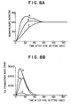
- Fig. 8A shows the burning rate ratio in dependence of the time after fire setting.
- the burning rate ratio means the ratio of calorific value at respective times with respect to the calorific value of stable combustion which is taken as 100%.
- a curve A in Fig. 8 shows the change of the burning rate as observed in a test conducted with a kerosene stove, when the ratio of air discharge rate between the inner and outer flames sleeves 2 and 3, i.e. the ratio of area of pores between these sleeves in the region near the auxiliary wick 9b, is selected to be 1:1. In this case, a high rate of generation of carbon monoxide was observed as will be seen from a curve (a) in Fig. 8B. Curves B, (b) and C (c) in Fig. 8A and Fig.
- the auxiliary wick 9c is kept in the state of dry burning so that no substantial deposition of tar was found on the auxiliary wick 9c. This favorable effect is maintained for a long period of time, because the liquid fuel is sucked up and supplied to the auxiliary wick at each time the lower end of the auxiliary wick 9c is immersed in the liquid fuel when the wick 9 as a whole is lowered for extinction.
- the fuel is evaporated from the surface of fuel evaporating portion 9a of the main wick 9b. Since this surface is maintained at a high temperature and allowed to be contacted by oxygen, there is a possibility of generation and deposition of tar.
- the deposition of the tar is serious particularly when a part of the liquid fuel is deteriorated due to oxidation or change of quality, or when a component having a high boiling point is added to the fuel, as in the case of mixing of salad oil, light oil, machine oil and so forth in white kerosene.
- the area of the air pores 2a' in the region of the inner flame sleeve 2 facing the fuel evaporating portion 9a of the main wick 9b is increased to permit the supply of air at a large rate, thereby to maintain a sufficiently large rate of fuel evaporation while lowering the temperature of the main wick 9b, so that the deposition of tar is effectively suppressed.
- the fuel evaporating portion 9a of the main wick 9b is allowed to receive the air at a sufficiently large rate to promote the evaporation of the liquid fuel to recover the necessary burning rate and, at the same time, the tar deposition is thermally decomposed and removed by the pore flames "f" opposing to the fuel evaporating portion, so that a stable burning is maintained and the generation of offensive odor and carbon monoxide is suppressed effectively for a long period of use.
- the increase of the number and size of the air pores 2a' of the air pore rows 2a opposing to the main wick 9b is quite effective from the view point of cleaning of the main wick. Namely, due to the increased number and size of the pores 2a', it is possible to obtain strong pore flames "f" to effectively increase the temperature of the fuel evaporating portion 9a of the main wick 9b, thereby to enhance the effect of dry burning which is intentionally conducted by continuing the burning while stopping the fuel supply so as to burn the tar deposition to clean the wick.
- the fuel evaporating portion 9a of the main wick 9b is disposed at the inner side of the auxiliary wick 9c, and the opening area of the pores 9a' in the pore rows 2a of the inner flame sleeve 2 is selected to be greater than that of the pores 3a formed in the outer flame sleeve.
- the liquid fuel burning device of the invention can maintain a good and stable burning characteristics over a long period of time.
Landscapes
- Engineering & Computer Science (AREA)
- Chemical & Material Sciences (AREA)
- Combustion & Propulsion (AREA)
- Mechanical Engineering (AREA)
- General Engineering & Computer Science (AREA)
- Wick-Type Burners And Burners With Porous Materials (AREA)
Description
- The present invention relates to a liquid fuel burning device including an inner flame sleeve having a plurality of air pores in its wall, an outer flame sleeve surrounding said inner flame sleeve at a distance from the latter to form therebetween an annular burning space, said outer flame sleeve also having a plurality of air pores formed in the wall thereof and a wick having a fuel evaporating portion projecting into the burning space.
- A conventional liquid fuel burning device disclosed in DE-C-640 932 includes an inner flame sleeve having a plurality of air pores in its inner wall, an outer sleeve surrounding said inner flame sleeve at a distance from the latter to form therebetween an annular burning space, said outer flame sleeve also having a plurality of air pores formed in the wall thereof, and a wick having a fuel evaporating portion projecting into the burning space. The inner and outer surface of said wick is covered by an inner and outer supporting sleeve, respectively, in such a manner that only a very short upper portion of said wick remains uncovered. Therefore only one horizontal row of air pores formed in said inner and outer flame sleeve is facing the fuel evaporation portion of said wick.
- This conventional liquid fuel burning device, however, suffers a serious drawback. Namely, since the end of the wick where the liquid fuel is evaporated is subjected to a high temperature and sufficient oxygen during the burning, a part of the liquid fuel is easily changed into tar through oxidation, polymerization and condensation. The tar inconveniently deposits on the fuel evaporating portion of the wick to cause various troubles as stated below.
- (1) The deposition of tar covers the surface of the fuel evaporating portion and clogs the internal capillary tubes to restrain the sucking action of fuel, as well as evaporation, resulting in a lowered rate of burning.
- (2) The lowered rate of burning causes an imbalance between the air and fuel in the burning area to cause an imperfect burning to generate large amount of carbon monoxide which is harmful to human bodies, while releasing offensive odor and much carbon.
- (3) The deposition of tar increases in the volume, i.e. thickness, of the fuel evaporating portion of the wick. This dangerously interferes with the wick being lowered for extinction.
- (4) The tar inconveniently flows into the gap between the wick and the peripheral metallic sleeve supporting the wick, so as to allow a stick of the wick to cause the same danger as mentioned in the above item (3).
- (5) The accumulation of tar at the end of the fuel evaporating portion makes the starting of the burning device difficult, and retards the propagation of flame after putting a fire on the wick. Before the flame is propagated over the entire periphery of the wick, a large amount of carbon monoxide and carbon, as well as offensive odor, is released.
- The deposition of tar which causes the troubles mentioned in above items (1) to (5) is serious particularly when a part of the fuel has been degraded due to, for example, generation of oxides or peroxides as a result of application of heat or leaving the fuel for a long time in sun light, or when a different fraction of higher boiling point is mixed in the fuel as in the case of mixing of light oil, heavy oil, machine oil, salad oil or the like in the kerosene. In these cases, the deposition of tar takes place in. a short period of time.
- Accordingly, an object of the invention is to provide a liquid fuel burning device enabling the decomposition and removal of tar produced from the wick.
- To this end, according to the invention, there is provided a liquid fuel burning device of the type mentioned above, characterized by comprising a plurality of spaced vertical row of air pores formed in the wall of at least one of said inner flame sleeve and said outer flame sleeve facing said fuel evaporating portion and by further comprising a horizontal row of air pores formed in the region of above said vertical row of air pores, said air pores of horizontal row being arranged at a higher density than the pores formed in other region of said wall.
- The above and other objects, as well as advantageous features of the invention will become clear from the following description of the preferred embodiment taken in conjunction with the accompanying drawings.
-
- Fig. 1 is a partly sectioned front elevational view of a liquid fuel burning device constructed in accordance with an embodiment of the invention;
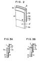
- Fig. 2 is a perspective view of a portion of a modified wick;
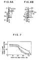
- Figs. 3A, 3B, 5, 6A and 6B are illustrations of operation of the liquid fuel burning device shown in Fig. 1;
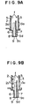
- Figs. 9A and 9B are illustrations of operation of the liquid fuel burning device provided with the wick shown in Fig. 2; and
- Figs. 4, 7, 8A and 8B show the characteristics of the liquid fuel burning device shown in Fig. 1.
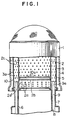
- Referring to Fig. 1, a burner sleeve assembly 1 includes an
inner flame sleeve 2,outer flame sleeve 3 and an outer cylinder 4 arranged coaxially with one another. Aburning space 5 is formed between theinner flame sleeve 2 and theouter flame sleeve 3. Awick 9 fixed to awick holder 8 is disposed between a wickinner sleeve 6 and a wickouter sleeve 7. The end of thewick 9 constituting afuel evaporating portion 9a is projected into theburning space 5. Thewick 9 is adapted to be extended upwardly and retracted downwardly together with thewick holder 8 by means of a suitable wick driving means (not shown). - In the surface of the wall of the
inner flame sleeve 2 facing thefuel evaporating portion 9a, there are formed a plurality ofvertical rows 2a each having a plurality ofair pores 2a'. Also,air pores 2b are densely formed along a horizontal circumferential row in the same surface of theinner flame sleeve 2 at a portion of the latter above thevertical rows 2a of air pores. Furthermore, in the same surface of theinner flame sleeve 2, formed are a plurality of horizontal rows ofair pores 2c such that thepores 2c are arranged in a staggered manner. On the other hand, theouter flame sleeve 3 is provided with a plurality of horizontal rows ofair pores 3a arranged also in a staggered manner. - A disc-
shaped partition plate 10 is attached to the inner side of theinner flame sleeve 2. Thepartition plate 10 is provided with a plurality ofapertures 10a formed therein. The total area of theseapertures 10a is selected to be less than 20% of the entire area of thepartition plate 10, i.e. the horizontal cross-sectional area of theinner flame sleeve 2 as measured at the inside of the latter. - According to the modification shown in Fig. 2, the wick generally designated at a
reference numeral 9 includes further amain wick 9b and anauxiliary wick 9c for propagation of flame attached to the outer periphery of the upperfuel evaporating portion 9a, through the medium of a fuelimpermeable member 9d such as an aluminum foil. The lower end of theauxiliary wick 9c is spaced from the level (broken line A-A') of the fuel during the normal burning of the fuel, but is immersed in the liquid fuel as thewick 9 as a whole is lowered for extinction. The liquid fuel level when thewick 9 is lowered is shown by a broken line B-B'. - A
reference numeral 9e designates a tape for fixing the wick. - The number and diameter of the
air pores 3a formed in the wall surface facing theauxiliary wick 9c, i.e. the pores formed in the predetermined area of theouter flame sleeve 3, are selected to be smaller than the number and diameter of the pores formed in the other portion, e.g. thepores 2a formed in a predetermined area of theinner flame sleeve 2 directly facing thefuel evaporating portion 9a of themain wick 9b. - At the beginning period of the burning, as will be seen from Fig. 3A, flame "f" is stably formed on the
air pores 2b which are densely arranged along the horizontal line. The heat generated by the flame is delivered to thefuel evaporating portion 9a as the evaporation latent heat to promote the evaporation of the fuel in thatportion 9a. Air for promoting the evaporation is supplied through thevertical rows 2a of air pores. In this region, however, no flame is formed partly because of a too high concentration and partly because of the low temperature. - As the deposition of the tar "t" on the
fuel evaporating portion 9a becomes appreciable as a result of a long use, the temperature of thefuel evaporating portion 9a and its vicinity is raised and the concentration of gaseous fuel becomes low in the area around therows 2a of air pores, so that the pore flame "f" is formed in this region, as illustrated in Fig. 3B. - Since the pores in the
pore rows 2a are arranged in vertical rows, the air released from the lower pores merges in the air released from the uppermost pores, so that an inflammable mixture is easily formed around the uppermost pores even by a slight reduction of fuel evaporation rate. The pore flame "f", therefore, begins with the region around the uppermost pores of thevertical rows 2a. Since this pore flame "f" takes a position opposing to thefuel evaporating portion 9a, the most part of the heat produced by the pore flame "f" is delivered to thefuel evaporating portion 9a to recover the fuel evaporation rate while thermally decomposing and removing the tar "t", thereby to prevent the reduction of evaporation of the liquid fuel. - In the event that the pore flame "f" on the pores of the uppermost stage is still insufficient, the pore flame "f" is naturally spread to the
pores 2a' of the second stage to assist and promote the increase of the fuel evaporation rate and the removal of the tar "t", thanks to the arrangement of pores invertical rows 2a. Thus, the pore flame "f" is formed in accordance with the extent of deposition of the tar "t" on thefuel evaporating portion 9a, to compensate for the reduction of fuel evaporation rate attributable to the tar deposition, and to decompose and remove the tar "t", thereby to ensure a stable burning for a long period of time while avoiding the release of carbon monoxide, offensive smell and carbon. - In order to confirm the effect of the invention, a test was conducted using a kerosene stove with kerosene to which added was 0.1 vol% of salad oil, to obtain a result as shown in Fig. 4. The full-line curve A shows the burning characteristics of the conventional stove in relation to time. It will be seen that the heat output (Kcal/h) of the stove comes down to a level of 70% of the rating heat output and rate of generation of carbon monoxide and offensive odor was observed after a 10-hour operation. In contrast, as will be seen from the full-line curve B, the stove of the invention could maintain a heat output well exceeding 90% of the rating heat output even after 100-hour operation. In addition, no substantial generation of carbon monoxide and offensive odor was observed.
- In the liquid fuel burning device of the described embodiment, it is possible to maintain a stable and superior burning characteristics, without suffering any deterioration of the starting and flame propagation characteristics, thanks to the decomposition and removal of the tar "t".
- In addition, the undesirable increase of the thickness of the
fuel evaporating portion 9a, as well as the stick of the wick to the metallic portion such as the inner andouter wick sleeves - These advantages will be further enhanced by composing the
fuel evaporating portion 9a with a material which makes a catalytic action for thermally decomposing the hydrocarbon, e.g. silica-alumina, or making metal oxides such as alkali metal compounds CrZ03 or the like present on the surface of thefuel evaporating portion 9a. - The arrangement of the
air pore rows 2a andair pores 2b of the described embodiment is not exclusive. Namely, therows 2a of air pores and the air pores 2b may be formed either in theinner flame sleeve 2 orouter flame sleeve 3 or in both of these sleeves. - A part of the air flowing upward through the burner sleeve 1 due to the natural draft is made to pass through the
inner flame sleeve 2. This part of air is partly interrupted by thepartition plate 10 to produce lateral dynamic and static pressures which act to direct the air toward therows 2a of air pores andair pores 2b. More specifically, although the most part of air flowing upwardly through the wick inner sleeve. 6 as indicated by an arrow A is allowed to flow upward through theapertures 10a of thepartition plate 10, the other part of air is directed toward the burningspace 5 through therows 2a of air pores and the air pores 2b beneath thepartition plate 10. Particularly, a large part of the air stream A is directed toward the air pores 2b just under thepartition plate 10, due to the resistance imposed by the latter. In consequence, a mixture rich in air and, hence, capable of easily forming the pore flame "f" is formed in the region around thepores 2b. Therefore, a stable pore flame "f" is formed in this region as illustrated in Fig. 5. This pore flame "f" delivers the heat to thefuel evaporating portion 9a of thewick 9 at a constant rate without being affected by external disturbance such as wind and impact, so that the rate of evaporation of the fuel is very much stabilized. - In addition, the dense arrangement of the air pores 2b just under the
partition plate 10 affords a sufficient temperature rise of the inner flame sleeve, due to the interaction between the flames on adjacent pores, which in turn further stabilizes the pore flame "f" to avoid bad influence of the external disturbance factors. - In order to evaluate the stability of the flame, a test was conducted with three types of burner sleeve 1 to investigate the relationship between the aperture area ratio of the
partition plate 10 which will be mentioned later and flame stability factor which also will be mentioned later. Namely, the aperture area ratio in this specification is defined as the ratio of the total area of apertures formed in the partition plate and the whole area of thepartition plate 10 which is given as nR2 (R represents the radius of plate 10). Also, the flame stability factor is the ratio between the number of pore flames "f" which remain on the pores just under thepartition plate 10 after blowing of wind at a velocity of 2 to 3 m/sec from the front side of the burner sleeve 1 and the number of the pore flames "f" formed on the pores before the blowing of wind. The three types of burner sleeves 1 used in this test havepores 2a in the vertical rows of 1.5 mm dia, 1.3 mm dia and 1.2 mm dia, respectively. The result of this test is shown in Fig. 7, in which the curve (1) is the result of having 1.5 mm dia pores, the curve (2) having 1.3 mm dia pores and the curve (3) having 1.2 mm dia pores. From Fig. 7, it will be seen that in each case a high stability of the pore flame "f" is obtained when the aperture area ratio falls below about 20%. - Furthermore, by concentrating the
apertures 10 a to the central region of thepartition plate 10, it is possible to form a returning flow layer of air as illustrated in Fig. 6B to prevent the drop of temperature of the wall ofinner flame sleeve 2, in contrast to the conventional arrangement in which the air is allowed to flow upwardly along the inner peripheral surface of theinner flame sleeve 2 as illustrated in Fig. 6A. Therefore, in the device of the invention, the pore flame is further stabilized, and, even when the fuel evaporation is lowered due to the tar deposition, the pore flame can easily be propagated to the pores in the lower stages, because the temperature around these pores in the lower stage is sufficiently high thanks to the heating effect provided by the returning flow layer of air. This effect will be explained in more detail hereinunder. When the fuel evaporation rate at thefuel evaporating portion 9a is decreased, the region of inflammable mixture of suitable air-fuel ratio is spread to the lower portion of the burningspace 5, as stated before. In the conventional arrangement, however, the pore flame could hardly be spread to the pores of lower stages, because the temperature of theinner flame sleeve 2 was low. According to the invention, this problem is overcome because the temperature of theinner flame sleeve 2 is maintained sufficiently high. Therefore, "new" pore flames as indicated by "f" are conveniently formed as the fuel evaporation rate is lowered, so that the rate of delivery of heat to the fuel evaporating portion is increased to recover the required fuel evaporation rate, while thermally decomposing and removing the tar "t" depositing on thefuel evaporating portion 9a of thewick 9. - Since the
partition plate 10 acts as a heat radiating member for emitting the heat from theinner flame sleeve 2, it is preferably made of a material having a low heat conductivity such as stainless steel, or other metals coated with a ceramic, in order to preserve the heat. By so doing, it is possible to further enhance the above-described advantageous effect. - As has been described, by selecting the total area of
apertures 10a at a level below 20% of the whole area of thepartition plate 10, i.e. the horizontal cross-sectional area of theinner flame sleeve 2 as measured at the inside of the latter, it is possible to stabilize the pore flames on the pores disposed at the lower portion of the inner air pores. In addition, the release of heat from theinner flame sleeve 2 is effectively suppressed by thepartition plate 10 made of a material having low heat conductivity. In consequence, the state of burning of the liquid fuel is remarkably stabilized and various problems attributable to the deposition of tar is eliminated advantageously. - Hereinafter, an explanation will be made as to the advantageous effects peculiar to the invention as set forth in the
Claims - As the fire is put on a portion of the flame-
propagation auxiliary wick 9c by a heater or the like, the flame is propagated rapidly over the entire circumference of theauxiliary wick 9c. At the same time, this flame promotes the evaporation of the fuel from thefuel evaporating portion 9a of themain wick 9b to permit a smooth transition to the stable burning in the burningspace 5. As explained before in connection with Fig. 2, the lower end of theauxiliary wick 9c in this state is spaced from the liquid fuel surface. In addition, since theauxiliary wick 9c is isolated from themain wick 9b by the fuelimpermeable member 9d, no additional supply of the liquid fuel is made to theauxiliary wick 9. Therefore, as the fuel initially contained by theauxiliary wick 9c is consumed away, a state so-called dry burning is created on theauxiliary wick 9c. - If the total area of the
air pores 3a formed in the region of theouter flame sleeve 3 opposing to theauxiliary wick 9c is selected as large as that in the other region of thesleeve 3, there will be a vigorous formation of flame in this region to cause a rapid increase of the burning rate in the burningspace 5. In this state, however, the upper part of the burningspace 5, i.e. the upper portions of the inner andouter flame sleeves pores 3a formed in the region near theauxiliary wick 9c are selected to be smaller than those of thepores 3a formed in the remainder region on theouter flame sleeve 3a, so as to restrain the rate of discharge of the air. In consequence, the evaporation of the fuel is promoted only slowly and the rate of evaporation of fuel from themain wick 9b is increased correspondingly to the decrease of the liquid fuel contained by theauxiliary wick 9c. In consequence, the state of burning is progressively changed into the stable burning in a smooth manner while achieving an almost perfect burning in the transient period. - Fig. 8A shows the burning rate ratio in dependence of the time after fire setting. The burning rate ratio means the ratio of calorific value at respective times with respect to the calorific value of stable combustion which is taken as 100%. A curve A in Fig. 8 shows the change of the burning rate as observed in a test conducted with a kerosene stove, when the ratio of air discharge rate between the inner and
outer flames sleeves auxiliary wick 9b, is selected to be 1:1. In this case, a high rate of generation of carbon monoxide was observed as will be seen from a curve (a) in Fig. 8B. Curves B, (b) and C (c) in Fig. 8A and Fig. 8B respectively show the characteristics as observed when the above-mentioned ratio was selected to be 2:1 and 3:1, respectively. As will be realized from the curves C and (c), no excessive burning immediately after the start up was observed and the generation of carbon monoxide is remarkably reduced when the above-mentioned ratio is selected to be 3:1. - During the steady burning of the liquid fuel in the burning device, the
auxiliary wick 9c is kept in the state of dry burning so that no substantial deposition of tar was found on theauxiliary wick 9c. This favorable effect is maintained for a long period of time, because the liquid fuel is sucked up and supplied to the auxiliary wick at each time the lower end of theauxiliary wick 9c is immersed in the liquid fuel when thewick 9 as a whole is lowered for extinction. - In the steady state of burning, the fuel is evaporated from the surface of
fuel evaporating portion 9a of themain wick 9b. Since this surface is maintained at a high temperature and allowed to be contacted by oxygen, there is a possibility of generation and deposition of tar. The deposition of the tar is serious particularly when a part of the liquid fuel is deteriorated due to oxidation or change of quality, or when a component having a high boiling point is added to the fuel, as in the case of mixing of salad oil, light oil, machine oil and so forth in white kerosene. In such cases, there is a heavy deposition of tar to cause a clogging of the surface of thefuel evaporating portion 9a of themain wick 9b or the internal capillary tubes, in a comparatively short period of time. In consequence, the evaporation of the liquid fuel is restrained to cause an imperfect burning to permit the release of carbon monoxide, carbon and the offensive odor. In the described embodiment of the invention, the area of the air pores 2a' in the region of theinner flame sleeve 2 facing thefuel evaporating portion 9a of themain wick 9b is increased to permit the supply of air at a large rate, thereby to maintain a sufficiently large rate of fuel evaporation while lowering the temperature of themain wick 9b, so that the deposition of tar is effectively suppressed. - In the event that the fuel evaporation rate is decreased due to the accumulation of the tar, the mixture of air-fuel ratio suitable for catching fire is easily formed in the region around the
fuel evaporating portion 9a of themain wick 9b, because air is supplied at a high rate to this region. Therefore, the state of burning is changed from that shown in Fig. 9A to the state shown in Fig. 9B as the steady burning is commenced. As a result, thefuel evaporating portion 9a of themain wick 9b is allowed to receive the air at a sufficiently large rate to promote the evaporation of the liquid fuel to recover the necessary burning rate and, at the same time, the tar deposition is thermally decomposed and removed by the pore flames "f" opposing to the fuel evaporating portion, so that a stable burning is maintained and the generation of offensive odor and carbon monoxide is suppressed effectively for a long period of use. It is to be noted that, by increasing the diameter ofpores 2a' in therows 2a of pores in the area close to thefuel evaporating portion 9a of themain wick 9b, the tendency of the formation of the pore wick "f" is increased and the removal of the tar deposition is accelerated. For further enhancing these effects, it is effective also to increase the number and size of the air pores 3a of theouter flame sleeve 3. - It is also to be noted that the increase of the number and size of the air pores 2a' of the
air pore rows 2a opposing to themain wick 9b is quite effective from the view point of cleaning of the main wick. Namely, due to the increased number and size of thepores 2a', it is possible to obtain strong pore flames "f" to effectively increase the temperature of thefuel evaporating portion 9a of themain wick 9b, thereby to enhance the effect of dry burning which is intentionally conducted by continuing the burning while stopping the fuel supply so as to burn the tar deposition to clean the wick. - In the described embodiment, the
fuel evaporating portion 9a of themain wick 9b is disposed at the inner side of theauxiliary wick 9c, and the opening area of thepores 9a' in thepore rows 2a of theinner flame sleeve 2 is selected to be greater than that of thepores 3a formed in the outer flame sleeve. Obviously, this positional and size relationships may be reversed without causing any substantial difference in effect. - As will be understood from the foregoing description, according to the invention, it is possible to eliminate the reduction of burning rate due to deposition of tar and to obviate various problems due to the imperfect burning attributable to the reduction in the burning rate, e.g. generation of noxious carbon monoxide and offensive odor. In addition, the undesirable increase of volume of the fuel evaporating portion, as well as the stick of the wick to the metallic portions such as wick guide sleeve or wick outer sleeve, is effectively avoided to ensure a smooth driving of the wick up and down. These advantageous effects are obtainable without any deterioration of burning characteristics in the transient period between the start up of the burning device to the steady burning nor the start up characteristics are never affected. It is also to be noted that the stable burning is maintained regardless of any external disturbance factors such as wind, temperature change, mechanical impact and so forth.
- In consequence, the liquid fuel burning device of the invention can maintain a good and stable burning characteristics over a long period of time.
Claims (5)
Applications Claiming Priority (6)
| Application Number | Priority Date | Filing Date | Title |
|---|---|---|---|
| JP141214/80 | 1980-10-09 | ||
| JP55141214A JPS5765510A (en) | 1980-10-09 | 1980-10-09 | Combustor for liquid fuel |
| JP158619/80 | 1980-11-10 | ||
| JP55158619A JPS5782607A (en) | 1980-11-10 | 1980-11-10 | Liquid fuel combustor |
| JP40923/81 | 1981-03-20 | ||
| JP4092381A JPS603130B2 (en) | 1981-03-20 | 1981-03-20 | liquid fuel combustor |
Publications (2)
| Publication Number | Publication Date |
|---|---|
| EP0049865A1 EP0049865A1 (en) | 1982-04-21 |
| EP0049865B1 true EP0049865B1 (en) | 1984-02-22 |
Family
ID=27290642
Family Applications (1)
| Application Number | Title | Priority Date | Filing Date |
|---|---|---|---|
| EP81108033A Expired EP0049865B1 (en) | 1980-10-09 | 1981-10-07 | Liquid fuel burning device |
Country Status (4)
| Country | Link |
|---|---|
| US (1) | US4465457A (en) |
| EP (1) | EP0049865B1 (en) |
| CA (1) | CA1184484A (en) |
| DE (1) | DE3162386D1 (en) |
Families Citing this family (8)
| Publication number | Priority date | Publication date | Assignee | Title |
|---|---|---|---|---|
| US4619604A (en) * | 1983-06-30 | 1986-10-28 | Carrier Corporation | Flame radiator structure |
| US4515557A (en) * | 1984-01-19 | 1985-05-07 | Imanishi Kinzoku Kogyo Kabushiki Kaisha (Imarflex Mfg. Co.) | Kerosene combustion apparatus |
| JPH0663616B2 (en) * | 1984-03-31 | 1994-08-22 | 株式会社東芝 | Wick type liquid fuel combustor |
| JPS61128016A (en) * | 1984-11-28 | 1986-06-16 | Toyotomi Kogyo Co Ltd | Petroleum combustion device |
| US4776320A (en) * | 1985-07-31 | 1988-10-11 | Carrier Corporation | Device for inhibiting NOx formation by a combustion system |
| EP0239008B1 (en) * | 1986-03-25 | 1992-02-26 | Matsushita Electric Industrial Co., Ltd. | Combustion equipment |
| US5169306A (en) * | 1989-10-27 | 1992-12-08 | Toyotomi Co., Ltd. | Multi-cylinder combustion structure for oil burner |
| JP2004028517A (en) * | 2002-06-28 | 2004-01-29 | Tokkyo Kaihatsu Kk | Kerosene stove |
Family Cites Families (14)
| Publication number | Priority date | Publication date | Assignee | Title |
|---|---|---|---|---|
| US614080A (en) * | 1898-11-15 | Fredeeick r | ||
| DE125000C (en) * | ||||
| US242938A (en) * | 1881-06-14 | knipe | ||
| AT21866B (en) * | 1903-07-04 | 1905-10-25 | Paul Thausig | Round wick burner for liquid fuels. |
| US939121A (en) * | 1909-02-27 | 1909-11-02 | Christian Andersen Braaten | Liquid-fuel burner. |
| US1420003A (en) * | 1921-05-02 | 1922-06-20 | Wegman Jordan | Liquid-fuel burner |
| US2075242A (en) * | 1934-08-10 | 1937-03-30 | Vincent S Todaro | Liquid fuel burner |
| DE640932C (en) * | 1935-02-01 | 1937-01-15 | Curt Neubauer | Ceramic wick body arranged between an inner and an outer wick tube |
| US2197091A (en) * | 1938-09-01 | 1940-04-16 | Chace Co W M | Thermostatic control |
| US2546731A (en) * | 1946-02-16 | 1951-03-27 | Duff Walter James | Combustion tube fluid fuel burner |
| US2671439A (en) * | 1949-01-21 | 1954-03-09 | Wallin Foster Associates Inc | Wick-type oil burning heater |
| US2832404A (en) * | 1949-08-05 | 1958-04-29 | Thorpe Alfred Eric | Liquid fuel burners |
| GB763371A (en) * | 1954-04-15 | 1956-12-12 | Amalgamated Roadstone Corp Ltd | Improvements in or relating to wickless and pressureless oil burners |
| US3119438A (en) * | 1960-01-01 | 1964-01-28 | Karma New Malden Ltd | Liquid fuel burners |
-
1981
- 1981-10-02 US US06/308,139 patent/US4465457A/en not_active Expired - Fee Related
- 1981-10-05 CA CA000387293A patent/CA1184484A/en not_active Expired
- 1981-10-07 EP EP81108033A patent/EP0049865B1/en not_active Expired
- 1981-10-07 DE DE8181108033T patent/DE3162386D1/en not_active Expired
Also Published As
| Publication number | Publication date |
|---|---|
| DE3162386D1 (en) | 1984-03-29 |
| EP0049865A1 (en) | 1982-04-21 |
| US4465457A (en) | 1984-08-14 |
| CA1184484A (en) | 1985-03-26 |
Similar Documents
| Publication | Publication Date | Title |
|---|---|---|
| EP0049865B1 (en) | Liquid fuel burning device | |
| CA1196565A (en) | Combustion wick | |
| US2337673A (en) | Oil burner | |
| CA1172156A (en) | Liquid fuel combustion apparatus | |
| JPS6334361B2 (en) | ||
| US2086369A (en) | Burner | |
| US2144052A (en) | Liquid fuel burner | |
| EP0076568A1 (en) | A wick for combustion of liquid fuel | |
| JPS6333607B2 (en) | ||
| JPS6324325Y2 (en) | ||
| JPS5886312A (en) | liquid fuel combustion equipment | |
| JP3086524B2 (en) | Liquid fuel combustion device | |
| JPH0135248B2 (en) | ||
| JPS6331683B2 (en) | ||
| JPS6224685B2 (en) | ||
| JPS5843314A (en) | wick | |
| JPS6016205A (en) | oil burner | |
| JPS644087B2 (en) | ||
| JPS6364685B2 (en) | ||
| JPH0313484B2 (en) | ||
| US766358A (en) | Hydrocarbon-burner. | |
| KR850001526Y1 (en) | Oil heather | |
| JPS6126731Y2 (en) | ||
| JPS6323444B2 (en) | ||
| JPS6324209B2 (en) |
Legal Events
| Date | Code | Title | Description |
|---|---|---|---|
| PUAI | Public reference made under article 153(3) epc to a published international application that has entered the european phase |
Free format text: ORIGINAL CODE: 0009012 |
|
| 17P | Request for examination filed |
Effective date: 19811028 |
|
| AK | Designated contracting states |
Designated state(s): DE FR GB IT |
|
| ITF | It: translation for a ep patent filed | ||
| GRAA | (expected) grant |
Free format text: ORIGINAL CODE: 0009210 |
|
| AK | Designated contracting states |
Designated state(s): DE FR GB IT |
|
| REF | Corresponds to: |
Ref document number: 3162386 Country of ref document: DE Date of ref document: 19840329 |
|
| ET | Fr: translation filed | ||
| PGFP | Annual fee paid to national office [announced via postgrant information from national office to epo] |
Ref country code: FR Payment date: 19840928 Year of fee payment: 4 |
|
| PGFP | Annual fee paid to national office [announced via postgrant information from national office to epo] |
Ref country code: DE Payment date: 19841221 Year of fee payment: 4 |
|
| PLBE | No opposition filed within time limit |
Free format text: ORIGINAL CODE: 0009261 |
|
| STAA | Information on the status of an ep patent application or granted ep patent |
Free format text: STATUS: NO OPPOSITION FILED WITHIN TIME LIMIT |
|
| 26N | No opposition filed | ||
| GBPC | Gb: european patent ceased through non-payment of renewal fee | ||
| PG25 | Lapsed in a contracting state [announced via postgrant information from national office to epo] |
Ref country code: FR Free format text: LAPSE BECAUSE OF NON-PAYMENT OF DUE FEES Effective date: 19880630 |
|
| PG25 | Lapsed in a contracting state [announced via postgrant information from national office to epo] |
Ref country code: DE Effective date: 19880701 |
|
| REG | Reference to a national code |
Ref country code: FR Ref legal event code: ST |
|
| PG25 | Lapsed in a contracting state [announced via postgrant information from national office to epo] |
Ref country code: GB Effective date: 19881118 |