EP0049702B1 - Method of controlling the timing of an injection pump and apparatus using this method - Google Patents
Method of controlling the timing of an injection pump and apparatus using this method Download PDFInfo
- Publication number
- EP0049702B1 EP0049702B1 EP81890165A EP81890165A EP0049702B1 EP 0049702 B1 EP0049702 B1 EP 0049702B1 EP 81890165 A EP81890165 A EP 81890165A EP 81890165 A EP81890165 A EP 81890165A EP 0049702 B1 EP0049702 B1 EP 0049702B1
- Authority
- EP
- European Patent Office
- Prior art keywords
- injection pump
- engine
- pressure
- injection
- torque
- Prior art date
- Legal status (The legal status is an assumption and is not a legal conclusion. Google has not performed a legal analysis and makes no representation as to the accuracy of the status listed.)
- Expired
Links
Images


Classifications
-
- F—MECHANICAL ENGINEERING; LIGHTING; HEATING; WEAPONS; BLASTING
- F02—COMBUSTION ENGINES; HOT-GAS OR COMBUSTION-PRODUCT ENGINE PLANTS
- F02D—CONTROLLING COMBUSTION ENGINES
- F02D41/00—Electrical control of supply of combustible mixture or its constituents
- F02D41/30—Controlling fuel injection
- F02D41/38—Controlling fuel injection of the high pressure type
- F02D41/40—Controlling fuel injection of the high pressure type with means for controlling injection timing or duration
- F02D41/401—Controlling injection timing
-
- F—MECHANICAL ENGINEERING; LIGHTING; HEATING; WEAPONS; BLASTING
- F02—COMBUSTION ENGINES; HOT-GAS OR COMBUSTION-PRODUCT ENGINE PLANTS
- F02B—INTERNAL-COMBUSTION PISTON ENGINES; COMBUSTION ENGINES IN GENERAL
- F02B1/00—Engines characterised by fuel-air mixture compression
- F02B1/02—Engines characterised by fuel-air mixture compression with positive ignition
- F02B1/04—Engines characterised by fuel-air mixture compression with positive ignition with fuel-air mixture admission into cylinder
-
- F—MECHANICAL ENGINEERING; LIGHTING; HEATING; WEAPONS; BLASTING
- F02—COMBUSTION ENGINES; HOT-GAS OR COMBUSTION-PRODUCT ENGINE PLANTS
- F02B—INTERNAL-COMBUSTION PISTON ENGINES; COMBUSTION ENGINES IN GENERAL
- F02B3/00—Engines characterised by air compression and subsequent fuel addition
- F02B3/06—Engines characterised by air compression and subsequent fuel addition with compression ignition
-
- F—MECHANICAL ENGINEERING; LIGHTING; HEATING; WEAPONS; BLASTING
- F02—COMBUSTION ENGINES; HOT-GAS OR COMBUSTION-PRODUCT ENGINE PLANTS
- F02D—CONTROLLING COMBUSTION ENGINES
- F02D2200/00—Input parameters for engine control
- F02D2200/02—Input parameters for engine control the parameters being related to the engine
- F02D2200/04—Engine intake system parameters
- F02D2200/0402—Engine intake system parameters the parameter being determined by using a model of the engine intake or its components
-
- F—MECHANICAL ENGINEERING; LIGHTING; HEATING; WEAPONS; BLASTING
- F02—COMBUSTION ENGINES; HOT-GAS OR COMBUSTION-PRODUCT ENGINE PLANTS
- F02D—CONTROLLING COMBUSTION ENGINES
- F02D2200/00—Input parameters for engine control
- F02D2200/02—Input parameters for engine control the parameters being related to the engine
- F02D2200/04—Engine intake system parameters
- F02D2200/0406—Intake manifold pressure
-
- F—MECHANICAL ENGINEERING; LIGHTING; HEATING; WEAPONS; BLASTING
- F02—COMBUSTION ENGINES; HOT-GAS OR COMBUSTION-PRODUCT ENGINE PLANTS
- F02D—CONTROLLING COMBUSTION ENGINES
- F02D2200/00—Input parameters for engine control
- F02D2200/02—Input parameters for engine control the parameters being related to the engine
- F02D2200/06—Fuel or fuel supply system parameters
- F02D2200/0602—Fuel pressure
-
- F—MECHANICAL ENGINEERING; LIGHTING; HEATING; WEAPONS; BLASTING
- F02—COMBUSTION ENGINES; HOT-GAS OR COMBUSTION-PRODUCT ENGINE PLANTS
- F02D—CONTROLLING COMBUSTION ENGINES
- F02D2200/00—Input parameters for engine control
- F02D2200/02—Input parameters for engine control the parameters being related to the engine
- F02D2200/10—Parameters related to the engine output, e.g. engine torque or engine speed
- F02D2200/1002—Output torque
-
- F—MECHANICAL ENGINEERING; LIGHTING; HEATING; WEAPONS; BLASTING
- F02—COMBUSTION ENGINES; HOT-GAS OR COMBUSTION-PRODUCT ENGINE PLANTS
- F02D—CONTROLLING COMBUSTION ENGINES
- F02D2250/00—Engine control related to specific problems or objectives
- F02D2250/18—Control of the engine output torque
-
- Y—GENERAL TAGGING OF NEW TECHNOLOGICAL DEVELOPMENTS; GENERAL TAGGING OF CROSS-SECTIONAL TECHNOLOGIES SPANNING OVER SEVERAL SECTIONS OF THE IPC; TECHNICAL SUBJECTS COVERED BY FORMER USPC CROSS-REFERENCE ART COLLECTIONS [XRACs] AND DIGESTS
- Y02—TECHNOLOGIES OR APPLICATIONS FOR MITIGATION OR ADAPTATION AGAINST CLIMATE CHANGE
- Y02T—CLIMATE CHANGE MITIGATION TECHNOLOGIES RELATED TO TRANSPORTATION
- Y02T10/00—Road transport of goods or passengers
- Y02T10/10—Internal combustion engine [ICE] based vehicles
- Y02T10/40—Engine management systems
Description
Die Erfindung bezieht sich auf ein Verfahren zur Steuerung des Förderbeginns einer Einspritzpumpe für Einspritzbrennkraftmaschinen, insbesondere zur Kraftstoffeinspritzung an einem Dieselmotor, bei welchem Betriebsgrößen wie Drehzahl, Ladedruck, Motortemperatur öd. dgl., gemessen werden und das jeweils vom Motor abgegebene Drehmoment ermittelt wird, worauf in Abhängigkeit von dem ermittelten Motordrehmoment unter Berücksichtigung zumindest der gemessenen Drehzahl der Förderbeginn der Kraftstoffeinspritzpumpe verstellt wird, sowie auf eine zur Durchführung dieses Verfahrens geeignete Vorrichtung.The invention relates to a method for controlling the start of delivery of an injection pump for injection internal combustion engines, in particular for fuel injection on a diesel engine, in which operating variables such as speed, boost pressure, engine temperature or. Like., are measured and the torque output by the engine is determined, whereupon depending on the determined engine torque, taking into account at least the measured speed, the start of delivery of the fuel injection pump is adjusted, and on a device suitable for carrying out this method.
Es ist bekannt, daß die Schadstoffemission von Verbrennungsmotoren durch geeignete Wahl des Zündzeitpunktes bei Ottomotoren bzw. des Einspritzbeginns bei Einspritzbrennkraftmaschinen, insbesondere bei Dieselmotoren, wesentlich verringert werden kann. Dabei ist als Parameter für die relative Verlagerung dieses maßgeblichen Punktes neben der Motordrehzahl auch die Last von Wichtigkeit, die bei Ottomotoren durch die Einleitung des Unterdruckes im Saugrohr auf eine federbelastete Membrane zur Zündzeitpunktverstellung eingesetzt wird.It is known that the pollutant emissions from internal combustion engines can be significantly reduced by a suitable choice of the ignition point in gasoline engines or the start of injection in injection internal combustion engines, especially in diesel engines. In addition to the engine speed, the load that is used in gasoline engines by introducing the negative pressure in the intake manifold to a spring-loaded diaphragm to adjust the ignition timing is important as a parameter for the relative displacement of this relevant point.
Aus der DE-A-29 03 875 ist bereits eine Einrichtung zur Durchführung des eingangs genannten Verfahrens bekannt geworden, bei welcher neben einem der Drehzahl proportionalen elektrischen Signal die Stellung der Regelstange der Einspritzpumpe zur Ermittlung der Belastung des Motors herangezogen wird, wobei an der Regelstange ein Positionsgeber angeordnet ist.DE-A-29 03 875 has already disclosed a device for carrying out the method mentioned in the introduction, in which, in addition to an electrical signal proportional to the speed, the position of the control rod of the injection pump is used to determine the load on the engine, with the control rod a position transmitter is arranged.
Die Stellung der Regelstange ist aber insbesondere im Schubbetrieb ein ungenügendes Kriterium für das tatsächliche Ausmaß der Belastung des Motors und die Verwendung von Positionsgebern an der Regelstange erfordert eine zusätzliche Kompensation der thermischen Ausdehnung der Regelstange im Betrieb. Insbesondere bei Kraftfahrzeugmotoren, bei welchen häufig ein Schubbetrieb auftritt, kann daher mit der bekannten Einrichtung die Schadstoffemission nicht in der erforderlichen Weise optimiert werden.However, the position of the control rod is an insufficient criterion for the actual extent of the load on the motor, particularly in overrun mode, and the use of position sensors on the control rod requires additional compensation for the thermal expansion of the control rod during operation. In particular in motor vehicle engines, in which overrun occurs frequently, the known device cannot therefore optimize the pollutant emissions in the required manner.
Die Erfindung zielt nun darauf ab, ein Verfahren der eingangs genannten Art zu schaffen, mit welchem die Schadstoffemission und der Verbrauch einer Einspritzbrennkraftmaschine, insbesondere eines Dieselmotors, bei allen Betriebszuständen und insbesondere auch im Schubbetrieb verringert werden kann. Zur Lösung dieser Aufgabe besteht die Erfindung im wesentlichen darin, daß das Motordrehmoment aus wenigstens einem Meßwert für den Druck in der Hochdruckleitung der Einspritzpumpe oder dem Reaktionsmoment der Einspritzpumpe ermittelt wird. Sowohl das Reaktionsmoment der Einspritzpumpe als auch der Druck in der Hochdruckleitung der Einspritzpumpe lassen sich mit besonders einfachen und betriebssicheren Meßwertaufnehmern bestimmen, und es kann aus diesen Meßwerten auch im Schubbetrieb eine unmittelbare Steuergröße, welche dem tatsächlichen Belastungszustand des Motors Rechnung trägt, abgeleitet werden. Durch die Messung des Signals für das Motordrehmoment und die Verarbeitung dieser Meßgröße in einem Mikroprozessor läßt sich eine Stellgröße für die Verstellung des Einspritzzeitpunktes errechnen, wobei die lastabhängige Verstellung des Spritzbeginns beim Dieselmotor neben der Verringerung der Schadstoffemission auch eine Verbesserung der Leistungs- und Verbrauchswerte und eine Verminderung der thermischen und mechanischen Beanspruchung der Motorbauteile mit sich bringt.The invention now aims to provide a method of the type mentioned at the outset, with which the pollutant emission and the consumption of an injection internal combustion engine, in particular a diesel engine, can be reduced in all operating states and in particular also in overrun mode. To achieve this object, the invention essentially consists in that the engine torque is determined from at least one measured value for the pressure in the high-pressure line of the injection pump or the reaction torque of the injection pump. Both the reaction torque of the injection pump and the pressure in the high-pressure line of the injection pump can be determined with particularly simple and reliable measuring transducers, and an immediate control variable, which takes into account the actual load condition of the engine, can be derived from these measured values even in overrun mode. By measuring the signal for the engine torque and processing this measured variable in a microprocessor, a manipulated variable for the adjustment of the injection timing can be calculated, the load-dependent adjustment of the start of injection for the diesel engine in addition to the reduction in pollutant emissions also an improvement in performance and consumption values and a Reduction of the thermal and mechanical stress on the engine components.
Der Einspritzzeitpunkt muß in bekannter Weise in Abhängigkeit von der Motordrehzahl verstellt werden und die Verwendung eines Mikroprozessors ermöglicht es, in besonders einfacher Weise die Einflüsse von Motordrehzahl und Lastmoment gleichzeitig in eine gemeinsame Stellgröße für die Verstellung des Einspritzzeitpunktes umzusetzen. Die Verstellung des Einspritzzeitpunktes kann je nach Konstruktion der Einspritzpumpe in verschiedener Weise erfolgen ; beispielsweise kann bei einer Ausbildung, bei welcher die Einspritzpumpe über einen Kipphebei von einer Nockenwelle angetrieben wird, der Lagerpunkt durch Betätigung eines Exzenters verschoben werden, wodurch sich ein früherer oder späterer Einspritzzeitpunkt ergibt. Die Verstellung dieses Exzenters kann beispielsweise hydraulisch oder elektrisch, beispielsweise mittels eines Schrittmotors, erfolgen. Eine Einrichtung zur Feststellung des Förderbeginns einer Einspritzpumpe ist beispielsweise aus der AT-B-298 881 bekannt geworden. Bei dieser Ausbildung wird eine Kupplungsmuffe axial verschoben, wodurch die beiden durch die Muffe verbundenen Wellen, welche Außenverzahnungen mit verschiedenen Steigungen aufweisen, gegeneinander verdreht werden. Die Verschiebung der Kupplungsmuffe dieser bekannten Einrichtung kann beispielsweise hydraulisch, elektrisch und insbesondere mittels eines Schrittmotors erfolgen. Bei Einspritzpumpen, welche eine gesonderte Regelstange für die Verstellung des Einspritzzeitpunktes aufweisen, kann beispielsweise ein Schrittmotor unmittelbar kraftschlüssig mit dieser Regelstange gekoppelt werden. Ein Schrittmotor könnte ohne Zwischenschaltung von weiteren Bauteilen vom Mikroprozessor angesteuert werden. Für eine hydraulische Betätigung des Spritzverstellers müßte eine entsprechende mechanisch-hydraulische Umsetzung des Stellsignales erfolgen. Erfindungsgemäß kommen eine Reihe von Signalen für eine Auswertung in einem Mikroprozessor in Betracht, welche entweder direkt proportional der Last sind oder aber in einer einfachen Gesetzmäßigkeit zur Last stehen.The injection time must be adjusted in a known manner as a function of the engine speed, and the use of a microprocessor makes it possible in a particularly simple manner to simultaneously convert the influences of the engine speed and load torque into a common manipulated variable for adjusting the injection time. The injection timing can be adjusted in various ways depending on the design of the injection pump; For example, in a configuration in which the injection pump is driven by a camshaft via a tilting stroke, the bearing point can be shifted by actuating an eccentric, which results in an earlier or later injection timing. This eccentric can be adjusted, for example, hydraulically or electrically, for example by means of a stepping motor. A device for determining the start of delivery of an injection pump has become known, for example, from AT-B-298 881. In this embodiment, a coupling sleeve is axially displaced, as a result of which the two shafts connected by the sleeve, which have external toothings with different pitches, are rotated relative to one another. The displacement of the coupling sleeve of this known device can take place, for example, hydraulically, electrically and in particular by means of a stepping motor. In the case of injection pumps which have a separate control rod for the adjustment of the injection timing, a stepping motor can, for example, be directly and non-positively coupled to this control rod. A stepper motor could be controlled by the microprocessor without the interposition of other components. A corresponding mechanical-hydraulic conversion of the actuating signal would have to take place for hydraulic actuation of the spray adjuster. According to the invention, a series of signals are suitable for evaluation in a microprocessor, which are either directly proportional to the load or are based on a simple law.
Vorzugsweise kann das Verfahren so durchgeführt werden, daß das Motordrehmoment aus dem Spitzenwert oder dem Mittelwert des Leitungsdruckes in der Hochdruckleitung der Einspritzpumpe während eines Zylinderlastspiels ermittelt wird. Für verschiedene Einspritzmengen wird in einer Einspritzpumpe jeweils ein definierter Spitzendruck auftreten, wobei das Flächenintegral des Drucks über den Nockenwellenwinkel gemeinsam mit der Drehzahl des Motors ein unmittelbares Maß für das Motordrehmoment ergibt. In bevorzugter Weise wird hiebei das Motordrehmoment aus dem Druckverlauf in der Hochdruckleitung der Einspritzpumpe und aus der Motordrehzahl ermittelt, so daß eine noch genauere Ermittlung des tatsächlichen Be-Iastungszustandes des Motors ermöglicht wird.The method can preferably be carried out in such a way that the engine torque is determined from the peak value or the mean value of the line pressure in the high-pressure line of the injection pump during a cylinder load cycle. For different injection quantities, a defined peak pressure will occur in an injection pump, the surface integral of the pressure over the camshaft angle together with the engine speed giving a direct measure of the engine torque. The engine torque is preferably determined from the pressure curve in the high-pressure line of the injection pump and from the engine speed, so that an even more precise determination of the actual load condition of the engine is made possible.
Es kann aber auch das Reaktionsmoment der Einspritzpumpe aus den Kräften auf die Lagerpunkte der Einspritzpumpe ermittelt werden, wodurch sich ebenfalls in allen Betriebszuständen eine relativ genaue Ermittlung des tatsächlichen Belastungszustandes des Motors ergibt.However, the reaction torque of the injection pump can also be determined from the forces on the bearing points of the injection pump, which also results in a relatively precise determination of the actual load state of the engine in all operating states.
Die erfindungsgemäße Vorrichtung zur Durchführung dieses Verfahrens weist Meßwertaufnehmer für Betriebsgrößen wie Drehzahl, Ladedruck, Motortemperatur od. dgl., sowie wenigstens einen weiteren Meßwertaufnehmer zur Ermittlung des jeweils vom Motor abgegebenen Drehmomentes auf, welche Meßwertaufnehmer mit einem Prozessor zum Ausführen von mindestens einer Rechenoperation verbunden sind, welcher Prozessor einen Speicher zur Speicherung des auszuführenden Programms aufweist, und mit einer mit dem Prozessor verbundenen Betätigungseinrichtung zur Steuerung des Beginns der Kraftstofförderung der Einspritzpumpe. Die genannte Vorrichtung ist erfindunggemäß im wesentlichen dadurch gekennzeichnet, daß der Meßwertaufnehmer für die Ermittlung des Motordrehmoments als Druckmesser, insbesondere als Dehnungsmeßstreifen, für die Messung des Reaktionsmoments der Einspritzpumpe, des Druckes in der Hochdruckleitung der Einspritzpumpe oder des Druckverlaufes in der Hochdruckleitung der Einspritzpumpe ausgebildet ist. Es sind somit lediglich einfache und betriebssichere Bauteile für die Ermittlung des Belastungszustandes des Motors erforderlich, wobei vorzugsweise der Meßwertaufnehmer als piezoelektrischer Sensor für die Messung des Reaktionsmoments der Einspritzpumpe, des Druckes in der Hochdruckleitung der Einspritzpumpe oder des Druckverlaufes in der Hochdruck leitung der Einspritzpumpe ausgebildet sein kann.The device according to the invention for carrying out this method has transducers for operating variables such as speed, boost pressure, engine temperature or the like, and at least one further transducer for determining the torque output by the engine, which transducers are connected to a processor for performing at least one arithmetic operation Which processor has a memory for storing the program to be executed, and with an actuating device connected to the processor for controlling the start of fuel delivery of the injection pump. According to the invention, the above-mentioned device is essentially characterized in that the transducer for determining the engine torque is designed as a pressure gauge, in particular as a strain gauge, for measuring the reaction torque of the injection pump, the pressure in the high pressure line of the injection pump or the pressure curve in the high pressure line of the injection pump . Thus, only simple and reliable components are required for determining the load condition of the engine, the transducer preferably being designed as a piezoelectric sensor for measuring the reaction torque of the injection pump, the pressure in the high pressure line of the injection pump or the pressure curve in the high pressure line of the injection pump can.
Das den Mikroprozessor enthaltende Steuergerät kann mit einem Stellglied für die Einstellung des Beginns der Kraftstofförderung verbunden sein, welches von einem hydraulischen oder pneumatischen Arbeitskolben, einem elektrischen Hubmagneten, einem Elektromotor, einem elektrischen Stellmotor oder einem elektrischen Schrittmotor gebildet ist. Da dem Steuergerät nicht nur ein lastabhängiges Signal, sondern in der Regel auch ein der Drehzahl entsprechendes Signal zugeführt wird, lassen sich komplizierte Zusammenhänge mit einem gemeinsamen Steilglied dieser Art bewerkstelligen. Hiebei kann vorzugsweise so vorgegangen werden, daß auf Grund der in das Steuergerät eingesteuerten Drehzahl- und Lastsignale ein im Steuergerät gespeicherter Spritzverstellungskennwert abgerufen und dem Stellglied zugeordnet wird.The control unit containing the microprocessor can be connected to an actuator for setting the start of fuel delivery, which is formed by a hydraulic or pneumatic working piston, an electric solenoid, an electric motor, an electric servomotor or an electric stepping motor. Since the control device is not only supplied with a load-dependent signal, but generally also with a signal corresponding to the rotational speed, complicated relationships can be achieved with a common steep link of this type. Hiebei can preferably be carried out in such a way that, based on the speed and load signals input into the control unit, a spray adjustment characteristic value stored in the control unit is called up and assigned to the actuator.
Die EP-A-49 701, die EP-A-49 703 und die EP-A-49 704, welche gleiche Anmeide- und Prioritätstage haben, beschreiben jeweils ein ähnliches Verfahren zur Steuerung des Förderbeginns einer Einspritzpumpe sowie eine ähnliche Vorrichtung zur Durchführung dieses Verfahrens, wobei lediglich das Drehmoment durch unterschiedliche Parameter ermittelt wird.EP-A-49 701, EP-A-49 703 and EP-A-49 704, which have the same start-up and priority days, each describe a similar method for controlling the start of delivery of an injection pump and a similar device for carrying it out Method, wherein only the torque is determined by different parameters.
Die Erfindung wird nachfolgend an Hand der Zeichnung näher erläutert, in welcher eine Einrichtung zur last- und drehzahlabhängigen Spritzverstellung gezeigt ist, bei welcher die Spritzverstellung durch Differenzdrehbewegung zwischen pumpenantrieb und Pumpennockenwelle erzeugt wird.The invention is explained in more detail below with reference to the drawing, in which a device for load- and speed-dependent spray adjustment is shown, in which the spray adjustment is generated by differential rotation between the pump drive and the pump camshaft.
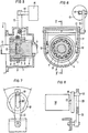
Fig. 1 und 2 zeigen den linearen Spritzverstellungsdrehzahlzusammenhang unabhängig vom Drehmoment-des Motors, wie sie bei konventionellen Regelungen vorgenommen wird. Die Spritzverstellungskurven im Motorkennfeld sind daher Geraden über der Drehzahl. In Fig. 3 und 4 sind drehzahl- und lastabhängige Spritzverstellungen dargestellt, wie sie erfindungsgemäß erzielbar sind. Fig. 5 und 6 zeigen eine Einrichtung zur Verstellung des Drehwinkels zwischen Pumpenantrieb und Pumpennockenweiie im Schnitt, wobei Fig. 5 einen Schnitt nach der Linie V-V der Fig. 6 darstellt. Fig. 7 und 8 zeigen eine Ausbildung des Stellgliedes als Schrittmotor, Fig. 9 einen schematischen Gesamtaufbau für ein Einspritzsystem, Fig. 10 eine Anordnung von Meßwertaufnehmern in der Einspritzleitung und an der Lagerung der Einspritzpumpe und Fig. 11 eine schematische Darstellung des Zusammenhanges zwischen den gemessenen Druckwerten und dem entsprechenden Motordrehmoment.FIGS. 1 and 2 show the linear injection adjustment speed relationship independent of the torque of the engine, as is done in conventional controls. The injection timing curves in the engine map are therefore straight lines over the speed. 3 and 4 speed and load-dependent spray adjustments are shown, as can be achieved according to the invention. 5 and 6 show a device for adjusting the angle of rotation between the pump drive and the pump cam in section, FIG. 5 showing a section along the line V-V of FIG. 6. 7 and 8 show an embodiment of the actuator as a stepper motor, Fig. 9 shows a schematic overall structure for an injection system, Fig. 10 shows an arrangement of transducers in the injection line and on the bearing of the injection pump and Fig. 11 shows a schematic representation of the relationship between the measured pressure values and the corresponding engine torque.
In Fig. 1 ist auf der Abszisse die Motordrehzahl in min-1 und auf der Ordinate das Motordrehmoment in Nm aufgetragen. Wie aus Fig. 2 hervorgeht, ergibt die Spritzverstellung bei verschiedenen Motordrehzahlen aufgetragen auf der negativen Ordinatenachse als Nockenwellenwinkel in Grad vor dem oberen Totpunkt des Kolbens der Brennkraftmaschine eine Gerade, welche bei der konventionellen Regelung unabhängig vom Motordrehmoment ist. Abweichend von derartigen konventionellen Verstellcharakteristiken sind in den Fig. 3 und 4 den Fig. 1 und 2 analoge Darstellungen für verschiedene Motordrehmomente wiedergegeben, wobei beliebige drehzahl- und lastabhängige Spritzverstellungen möglich sein sollen.In Fig. 1, the engine speed in min- 1 is plotted on the abscissa and the engine torque in Nm on the ordinate. As can be seen from FIG. 2, the spray adjustment at different engine speeds, plotted on the negative ordinate axis as camshaft angle in degrees before the top dead center of the piston of the internal combustion engine, results in a straight line which is independent of the engine torque in the conventional control. Deviating from such conventional adjustment characteristics, FIGS. 3 and 4, FIGS. 1 and 2 show analogous representations for different engine torques, any speed and load-dependent spray adjustments should be possible.
Die Möglichkeit für die Erzielung der in Fig. 3 und 4 wiedergegebenen Charakteristiken wird beispielsweise durch eine Ausbildung der Verstelleinrichtung für den Einspritzzeitpunkt nach den Fig. 5 und 6 gegeben, wobei das Stellglied von einer Steuereinrichtung angesteuert wird. In Fig. 5 und 6 ist mit 1 ein Gehäuse bezeichnet, das z. B. an dem Einspritzpumpengehäuse 2 angeflanscht ist. Im Gehäuse 1 befindet sich die Welle 3, die eine Außenverzahnung-4 besitzt. In der Welle 3 und im Gehäuse 1 ist eine zweite Welle 5 gelagert, die ebenfalls eine Außenverzahnung 6 trägt. Die Schiebemuffe 7, die eine Innenverzahnung 8 besitzt, ist über einen Gleitring 9 längs verschieblich. Durch die Kombination von Schrägverzahnungen bzw. Geradverzahnungen und Schrägverzahnungen wird durch die Längsverschiebung der Schiebemuffe 7 eine Relativbewegung der Wellen 3 und 5 zueinander erreicht. Auf dem Gleitring 9 sind Bolzen 10 angebracht, die über ein Gestänge 11, von einer Welle 12 und einem Außenhebel 13 betätigt werden. Je nach Lage des Außenhebels 13 ergibt sich nun eine ganz definierte Stellung der Schiebemuffe 7 und damit eine entsprechende Drehdifferenz zwischen den Wellen 3 und 5. Da die Drehdifferenz zwischen den Wellen 3 und 5 der Spritzverstellung proportional ist, kahn damit über den Außenhebel 13 jede beliebige Spritzverstellung erreicht werden. Der Außenhebel 13 ist über eine Stange 14 mit einem Stellmotor 15 verbunden. Dieser steuert in Funktion der Motorlast und des Motordrehmomentes die Lage der Schiebemuffe 7 und damit die Spritzverstellung. Der Stellmotor 15 kann sowohl nach dem hydraulischen, pneumatischen oder elektrischen Prinzip arbeiten. Voraussetzung ist, daß der Stellmotor 15 allen vorkommenden Last-und Drehzahländerungen des Verbrennungsmotors folgen kann.The possibility of achieving the characteristics shown in FIGS. 3 and 4 is, for example, by training the Ver Setting device for the injection timing given in FIGS. 5 and 6, wherein the actuator is controlled by a control device. 5 and 6, 1 denotes a housing which, for. B. is flanged to the
Fig. 7 und 8 zeigen ein Ausführungsbeispiel mit einem Schrittmotor 16. Der Schrittmotor zeichnet sich durch eine hohe Schrittfrequenz und eine hohe Genauigkeit aus. Auf der Welle 17 sitzt eine Scheibe 18, in der sich ein Bolzen 19 befindet. Dieser Bolzen 19 greift in eine Nut 20 des Außenhebels 13 ein. Je nach Drehlage des Schrittmotors wird nun der Außenhebel 13 betätigt und damit die erforderliche Spritzverstellung erreicht.7 and 8 show an embodiment with a
In Fig. 9 ist der schematische Gesamtaufbau für ein konventionelles Einspritzsystem dargestellt. Die Erfindung ist jedoch nicht notwendigerweise mit einem derartigen Einspritzsystem gekoppelt, sondern ist für jedes beliebige Einspritzsystem gedacht. An der Pumpe 21 befindet sich ein Regler 22 und der angebaute Spritzversteller 23. Über den Fahrfußhebel 24 wird nun der Außenhebel 25 des Reglers betätigt und damit die erforderliche Motordrehzahl bzw. Motorlast vorgewählt. An dem Schwungrad 26 des Verbrennungsmotors befindet sich ein Aufnehmer 27, der die Drehzahl mißt. Diese Drehzahl wird in das Steuergerät 28 übertragen. Gleichzeitig wird über einen Aufnehmer das Motordrehmoment festgestellt. In Fig. 9 ist dieser Aufnehmer mit 29 schematisch angedeutet. Das Signal des Meßwertaufnehmers 29, welches dem Lastmoment proportional ist, wird an das Steuergerät 28 weitergeleitet. In dem Steuergerät 28 sind die Soll-Spritzverstellungskennwerte gespeichert. Aus der Messung von Motordrehmoment und Motordrehzahl ist der Lastpunkt im Motorkennfeld genau definiert, und damit auch die erforderliche Spritzverstellung. Das Steuergerät 28 steuert nun entsprechend dem Motorlastpunkt den Stellmotor 15 an, der über den Außenhebel 13 die gewünschte Spritzverstellung einstellt.9 shows the overall schematic structure for a conventional injection system. However, the invention is not necessarily coupled to such an injection system, but is intended for any injection system. A
In Fig. 10 ist der Meßwertaufnehmer 29 als Druckgeber für den Einspritzdruck in die Einspritzleitung 31 eingeschaltet bzw. am Umfang der Einspritzleitung festgelegt. Die Einspritzpumpe ist hiebei mit 32 bezeichnet und wird von einer um die Achse 33 drehbaren, nicht dargestellten Nockenwelle angetrieben. Anstelle des Meßwertaufnehmers 29 oder zusätzlich zu demselben, kann eine Kraftmeßdose 34 am Aufleger der Einspritzpumpe 32 angeordnet sein, wobei die Einspritzpumpe 32 an einem schwenkbaren Arm 35 festgelegt ist. Der schwenkbare Arm 35 ist an einem starren Teil 36 des Motors angelenkt, so daß die Kraftmeßdose 34 die Reaktionskräfte der Einspritzpumpe 32 mißt. Die Signale des Meßwertaufnehmers 29 bzw. der Kraftmeßdose 34 werden an den Mikroprozessor in der Steuerschaltung 28 weitergeleitet.In Fig. 10, the
In Fig. 11 ist der gemessene Druck über den Nockenwellenwinkel aufgetragen. Verschiedene Einspritzmengen entsprechen nun den gemessenen Werten des Einspritzdruckes Pmaxi, Pmax2 und Pmax3. Jedem derartigen Spitzenwert entspricht ein mittlerer Druckwert Pm1, Pm2 bzw. Pms. Aus dem Kurvenverlauf läßt sich die Fläche unterhalb der jeweiligen Kurve durch Integration berechnen und die berechneten Flächen Alo A2 bzw. A3 ergeben ein Maß für das Motordrehmoment, wobei zusätzlich noch die Drehzahl des Motors berücksichtigt werden muß.11 the measured pressure is plotted against the camshaft angle. Different injection quantities now correspond to the measured values of the injection pressure P max i, P ma x 2 and P max3 . An average pressure value P m1 , P m2 or Pms corresponds to each such peak value. From the course of the curve, the area below the respective curve can be calculated by integration, and the calculated areas A lo A 2 or A 3 give a measure of the engine torque, the engine speed also having to be taken into account.
Als weitere Ausführungsform ist denkbar, daß die beliebige last- und drehzahlabhängige Spritzverstellung über eine lastabhängige Bedienung des Außenhebels der Einrichtung gemäß der AT-B-298881 erreicht wird. Die drehzahlabhängige Spritzverstellung kann in Abhängigkeit von dem beispielsweise in der AT-B-298 881 dargestellten Drehzahlmeßwerk erfolgen. Bei Verwendung ein- . es Mikroprozessors lassen sich die Werte für die Drehzahl und für lastabhängige Signale in beliebiger Weise kombinieren, sodaß den speziellen Erfordernissen einer bestimmten Brennkraftmaschine in verbessertem Maße Rechnung getragen werden kann.As a further embodiment, it is conceivable that the arbitrary load and speed-dependent spray adjustment is achieved via a load-dependent operation of the outer lever of the device according to AT-B-298881. The speed-dependent spray adjustment can take place as a function of the speed measuring mechanism shown, for example, in AT-B-298 881. When using a. The microprocessor can combine the values for the speed and for load-dependent signals in any way, so that the special requirements of a particular internal combustion engine can be taken into account to an improved extent.
Claims (6)
Priority Applications (1)
| Application Number | Priority Date | Filing Date | Title |
|---|---|---|---|
| AT81890165T ATE7944T1 (en) | 1981-10-08 | 1981-10-08 | METHOD FOR CONTROLLING THE START OF DELIVERY OF AN INJECTION PUMP AND DEVICE FOR CARRYING OUT THESE METHOD. |
Applications Claiming Priority (2)
| Application Number | Priority Date | Filing Date | Title |
|---|---|---|---|
| AT4999/80 | 1980-10-08 | ||
| AT499980 | 1980-10-08 |
Publications (3)
| Publication Number | Publication Date |
|---|---|
| EP0049702A2 EP0049702A2 (en) | 1982-04-14 |
| EP0049702A3 EP0049702A3 (en) | 1982-09-22 |
| EP0049702B1 true EP0049702B1 (en) | 1984-06-13 |
Family
ID=3570790
Family Applications (4)
| Application Number | Title | Priority Date | Filing Date |
|---|---|---|---|
| EP81890165A Expired EP0049702B1 (en) | 1980-10-08 | 1981-10-08 | Method of controlling the timing of an injection pump and apparatus using this method |
| EP81890164A Withdrawn EP0049701A3 (en) | 1980-10-08 | 1981-10-08 | Method of controlling the timing of an injection pump and apparatus using this method |
| EP81890167A Withdrawn EP0049704A3 (en) | 1980-10-08 | 1981-10-08 | Method of controlling the timing of an injection pump and apparatus using this method |
| EP81890166A Expired EP0049703B1 (en) | 1980-10-08 | 1981-10-08 | Method of controlling the timing of an injection pump and apparatus using this method |
Family Applications After (3)
| Application Number | Title | Priority Date | Filing Date |
|---|---|---|---|
| EP81890164A Withdrawn EP0049701A3 (en) | 1980-10-08 | 1981-10-08 | Method of controlling the timing of an injection pump and apparatus using this method |
| EP81890167A Withdrawn EP0049704A3 (en) | 1980-10-08 | 1981-10-08 | Method of controlling the timing of an injection pump and apparatus using this method |
| EP81890166A Expired EP0049703B1 (en) | 1980-10-08 | 1981-10-08 | Method of controlling the timing of an injection pump and apparatus using this method |
Country Status (4)
| Country | Link |
|---|---|
| US (1) | US4426982A (en) |
| EP (4) | EP0049702B1 (en) |
| JP (4) | JPS5793638A (en) |
| DE (2) | DE3164329D1 (en) |
Families Citing this family (46)
| Publication number | Priority date | Publication date | Assignee | Title |
|---|---|---|---|---|
| US4476837A (en) * | 1982-12-07 | 1984-10-16 | Stanadyne, Inc. | Method and system for fuel injection timing |
| JPS60138248A (en) * | 1983-12-27 | 1985-07-22 | Diesel Kiki Co Ltd | Fuel injection device for internal-combustion engine |
| US4708112A (en) * | 1985-07-11 | 1987-11-24 | Kokusan Denki Co. Ltd. | Electronic governor for an internal combustion engine |
| DE3605824A1 (en) * | 1986-02-22 | 1987-08-27 | Bosch Gmbh Robert | FUEL INJECTION PUMP FOR SUPPLYING THE COMBUSTION SPACE OF VEHICLE ENGINES PROVIDED FOR VEHICLE DRIVES |
| DE3771942D1 (en) * | 1986-06-19 | 1991-09-12 | Nippon Clean Engine Res | INTERNAL COMBUSTION ENGINE WITH FUEL INJECTION. |
| US4885935A (en) * | 1988-06-27 | 1989-12-12 | Ford Motor Company | Engine testing system |
| JPH0765523B2 (en) * | 1989-07-20 | 1995-07-19 | 日産自動車株式会社 | Fuel injection control device for diesel engine |
| DE4446246C2 (en) * | 1994-12-23 | 1999-10-21 | Mtu Friedrichshafen Gmbh | Process for regulating the load acceptance and acceleration behavior of supercharged internal combustion engines |
| DE19535056C2 (en) * | 1995-09-21 | 2000-09-14 | Daimler Chrysler Ag | Method for controlling fuel injection in a diesel engine |
| US5709196A (en) * | 1996-09-24 | 1998-01-20 | Caterpillar Inc. | Fuel control system for an internal combustion engine using a low cetane quality fuel |
| US6517330B2 (en) * | 2000-05-10 | 2003-02-11 | Kioritz Corporation | Reciprocating pump |
| EP1299628B1 (en) * | 2000-07-07 | 2006-08-02 | Siemens Aktiengesellschaft | Method for controlling a charge pressure in an internal combustion engine with an exhaust-gas turbocharger |
| US7743606B2 (en) * | 2004-11-18 | 2010-06-29 | Honeywell International Inc. | Exhaust catalyst system |
| US7182075B2 (en) * | 2004-12-07 | 2007-02-27 | Honeywell International Inc. | EGR system |
| US7591135B2 (en) * | 2004-12-29 | 2009-09-22 | Honeywell International Inc. | Method and system for using a measure of fueling rate in the air side control of an engine |
| US7328577B2 (en) | 2004-12-29 | 2008-02-12 | Honeywell International Inc. | Multivariable control for an engine |
| US7275374B2 (en) * | 2004-12-29 | 2007-10-02 | Honeywell International Inc. | Coordinated multivariable control of fuel and air in engines |
| US7165399B2 (en) * | 2004-12-29 | 2007-01-23 | Honeywell International Inc. | Method and system for using a measure of fueling rate in the air side control of an engine |
| US7467614B2 (en) | 2004-12-29 | 2008-12-23 | Honeywell International Inc. | Pedal position and/or pedal change rate for use in control of an engine |
| US20060168945A1 (en) * | 2005-02-02 | 2006-08-03 | Honeywell International Inc. | Aftertreatment for combustion engines |
| US7752840B2 (en) * | 2005-03-24 | 2010-07-13 | Honeywell International Inc. | Engine exhaust heat exchanger |
| US7469177B2 (en) * | 2005-06-17 | 2008-12-23 | Honeywell International Inc. | Distributed control architecture for powertrains |
| US7389773B2 (en) * | 2005-08-18 | 2008-06-24 | Honeywell International Inc. | Emissions sensors for fuel control in engines |
| US7155334B1 (en) | 2005-09-29 | 2006-12-26 | Honeywell International Inc. | Use of sensors in a state observer for a diesel engine |
| US7765792B2 (en) | 2005-10-21 | 2010-08-03 | Honeywell International Inc. | System for particulate matter sensor signal processing |
| US7357125B2 (en) * | 2005-10-26 | 2008-04-15 | Honeywell International Inc. | Exhaust gas recirculation system |
| US20070144149A1 (en) * | 2005-12-28 | 2007-06-28 | Honeywell International Inc. | Controlled regeneration system |
| US7415389B2 (en) * | 2005-12-29 | 2008-08-19 | Honeywell International Inc. | Calibration of engine control systems |
| US8060290B2 (en) | 2008-07-17 | 2011-11-15 | Honeywell International Inc. | Configurable automotive controller |
| US8620461B2 (en) * | 2009-09-24 | 2013-12-31 | Honeywell International, Inc. | Method and system for updating tuning parameters of a controller |
| US8504175B2 (en) | 2010-06-02 | 2013-08-06 | Honeywell International Inc. | Using model predictive control to optimize variable trajectories and system control |
| US9677493B2 (en) | 2011-09-19 | 2017-06-13 | Honeywell Spol, S.R.O. | Coordinated engine and emissions control system |
| US20130111905A1 (en) | 2011-11-04 | 2013-05-09 | Honeywell Spol. S.R.O. | Integrated optimization and control of an engine and aftertreatment system |
| US9650934B2 (en) | 2011-11-04 | 2017-05-16 | Honeywell spol.s.r.o. | Engine and aftertreatment optimization system |
| EP3051367B1 (en) | 2015-01-28 | 2020-11-25 | Honeywell spol s.r.o. | An approach and system for handling constraints for measured disturbances with uncertain preview |
| EP3056706A1 (en) | 2015-02-16 | 2016-08-17 | Honeywell International Inc. | An approach for aftertreatment system modeling and model identification |
| EP3091212A1 (en) | 2015-05-06 | 2016-11-09 | Honeywell International Inc. | An identification approach for internal combustion engine mean value models |
| EP3125052B1 (en) | 2015-07-31 | 2020-09-02 | Garrett Transportation I Inc. | Quadratic program solver for mpc using variable ordering |
| US10272779B2 (en) | 2015-08-05 | 2019-04-30 | Garrett Transportation I Inc. | System and approach for dynamic vehicle speed optimization |
| US10415492B2 (en) | 2016-01-29 | 2019-09-17 | Garrett Transportation I Inc. | Engine system with inferential sensor |
| US10036338B2 (en) | 2016-04-26 | 2018-07-31 | Honeywell International Inc. | Condition-based powertrain control system |
| US10124750B2 (en) | 2016-04-26 | 2018-11-13 | Honeywell International Inc. | Vehicle security module system |
| US11199120B2 (en) | 2016-11-29 | 2021-12-14 | Garrett Transportation I, Inc. | Inferential flow sensor |
| US10591003B2 (en) | 2017-06-16 | 2020-03-17 | Polaris Industries Inc. | Brake assembly shield and scraper |
| US11057213B2 (en) | 2017-10-13 | 2021-07-06 | Garrett Transportation I, Inc. | Authentication system for electronic control unit on a bus |
| US11293372B1 (en) | 2020-09-30 | 2022-04-05 | Ford Global Technologies, Llc | Method and system for adjusting operation of a fuel injector |
Family Cites Families (14)
| Publication number | Priority date | Publication date | Assignee | Title |
|---|---|---|---|---|
| GB1322502A (en) * | 1969-06-30 | 1973-07-04 | Cav Ltd | Compression ignition engine fuel systems |
| DE2011712C3 (en) * | 1970-03-12 | 1979-07-12 | Robert Bosch Gmbh, 7000 Stuttgart | Fuel injection system of a diesel internal combustion engine |
| FR2098627A5 (en) * | 1970-07-22 | 1972-03-10 | Bowles Fluidics Corp | |
| US3897766A (en) * | 1971-05-10 | 1975-08-05 | Massachusetts Inst Technology | Apparatus adapted to opto-electrically monitor the output of a prime mover to provide signals which are fed back to the input and thereby provide control of the prime mover |
| GB1429302A (en) * | 1972-04-04 | 1976-03-24 | Cav Ltd | Control systems for fuel supply systems for engines |
| GB1413099A (en) * | 1974-03-05 | 1975-11-05 | Fiat Spa | Electronic injection timing control for fuel injection pumps |
| GB1520427A (en) * | 1974-07-19 | 1978-08-09 | Bosch Gmbh Robert | Process of and system for regulating the operating behavaiour of an internal combustion engine |
| JPS5139285A (en) * | 1974-09-20 | 1976-04-01 | Katsumi Konno | JIDOTEIJIKYUJIKI |
| US4023403A (en) * | 1975-07-11 | 1977-05-17 | Scans Associates, Inc. | Method and apparatus for timing diesel engines |
| JPS5351945Y2 (en) * | 1975-07-26 | 1978-12-12 | ||
| US4166440A (en) * | 1977-09-29 | 1979-09-04 | The Bendix Corporation | Engine control system utilizing torque converter slip |
| FR2417642A1 (en) * | 1978-02-20 | 1979-09-14 | List Hans | FUEL INJECTION ENGINE, ESPECIALLY DIESEL ENGINE WITH INSTALLATION FOR ADJUSTING THE INJECTION INSTANT |
| GB2024462B (en) * | 1978-05-08 | 1983-03-30 | Bendix Corp | Integrated closed loop engine control system |
| DE2943950A1 (en) * | 1979-10-31 | 1981-05-14 | Robert Bosch Gmbh, 7000 Stuttgart | METHOD FOR IMPROVING THE ACCELERATION BEHAVIOR OF AN INTERNAL COMBUSTION ENGINE OPERATED WITH AN EXHAUST GAS TURBOCHARGER |
-
1981
- 1981-10-02 US US06/307,939 patent/US4426982A/en not_active Expired - Fee Related
- 1981-10-07 JP JP56158907A patent/JPS5793638A/en active Pending
- 1981-10-07 JP JP56158908A patent/JPS5793639A/en active Granted
- 1981-10-07 JP JP56158909A patent/JPS5793640A/en active Granted
- 1981-10-07 JP JP56158910A patent/JPS5793641A/en active Pending
- 1981-10-08 EP EP81890165A patent/EP0049702B1/en not_active Expired
- 1981-10-08 DE DE8181890166T patent/DE3164329D1/en not_active Expired
- 1981-10-08 EP EP81890164A patent/EP0049701A3/en not_active Withdrawn
- 1981-10-08 EP EP81890167A patent/EP0049704A3/en not_active Withdrawn
- 1981-10-08 EP EP81890166A patent/EP0049703B1/en not_active Expired
- 1981-10-08 DE DE8181890165T patent/DE3164206D1/en not_active Expired
Also Published As
| Publication number | Publication date |
|---|---|
| JPS5793639A (en) | 1982-06-10 |
| JPS5793641A (en) | 1982-06-10 |
| EP0049703B1 (en) | 1984-06-20 |
| DE3164329D1 (en) | 1984-07-26 |
| EP0049703A3 (en) | 1982-09-15 |
| US4426982A (en) | 1984-01-24 |
| JPS6225856B2 (en) | 1987-06-05 |
| EP0049703A2 (en) | 1982-04-14 |
| EP0049701A2 (en) | 1982-04-14 |
| EP0049702A3 (en) | 1982-09-22 |
| DE3164206D1 (en) | 1984-07-19 |
| EP0049702A2 (en) | 1982-04-14 |
| EP0049704A2 (en) | 1982-04-14 |
| JPS6225857B2 (en) | 1987-06-05 |
| EP0049701A3 (en) | 1982-09-15 |
| JPS5793640A (en) | 1982-06-10 |
| JPS5793638A (en) | 1982-06-10 |
| EP0049704A3 (en) | 1982-09-15 |
Similar Documents
| Publication | Publication Date | Title |
|---|---|---|
| EP0049702B1 (en) | Method of controlling the timing of an injection pump and apparatus using this method | |
| DE3833323C2 (en) | ||
| DE3210914C2 (en) | ||
| DE4000220C2 (en) | ||
| DE3128239C2 (en) | Method and device for controlling exhaust gas recirculation quantities | |
| DE3619956C2 (en) | ||
| DE102004054711A1 (en) | Internal combustion engine e.g. diesel engine, controlling method for motor vehicle, involves determining top dead center of crankshaft from structural noise signal according to phase relation obtained between noise signal and dead center | |
| DE112014004229T5 (en) | A system for adjusting a fuel injector actuator drive signal during a fuel injection event | |
| DE3522414A1 (en) | FUEL INJECTION SYSTEM FOR COMBUSTION ENGINES | |
| DE2807720A1 (en) | FUEL INJECTION DEVICE FOR COMBUSTION ENGINES, IN PARTICULAR FOR DIESEL ENGINES | |
| DE10319666A1 (en) | Method and device for setting a variable compression in an internal combustion engine | |
| DE3333931A1 (en) | FUEL INJECTION PUMP FOR A COMBUSTION ENGINE | |
| DE3622814C2 (en) | ||
| DE19650249A1 (en) | Shaft rotation angle and valve lift detection arrangement for engine | |
| EP0029019B1 (en) | Control system for internal-combustion engines | |
| EP0055245A2 (en) | Device for adjusting and coordinating a plurality of injection devices | |
| DE2708437C2 (en) | ||
| DE19534878B4 (en) | Method for automatic calibration of an angle mark transmitter on the crankshaft of a reciprocating internal combustion engine | |
| DE10305525B4 (en) | Method and device for adapting the pressure wave correction in a high-pressure injection system of a motor vehicle while driving | |
| EP1273795B1 (en) | Method and apparatus for injecting fuel | |
| WO2012013264A1 (en) | Method for operating a reciprocating piston engine | |
| DE3540811A1 (en) | FUEL INJECTION DEVICE FOR INTERNAL COMBUSTION ENGINES, IN PARTICULAR PUMP NOZZLE FOR AIR COMPRESSIVE INJECTION INTERNAL COMBUSTION ENGINES | |
| DE102008041522A1 (en) | Injection characteristic corrective fuel injection system | |
| DE19722316A1 (en) | Method of controlling self-igniting internal combustion engine | |
| DE102018104292A1 (en) | Sensor device for a length-adjustable connecting rod |
Legal Events
| Date | Code | Title | Description |
|---|---|---|---|
| PUAI | Public reference made under article 153(3) epc to a published international application that has entered the european phase |
Free format text: ORIGINAL CODE: 0009012 |
|
| AK | Designated contracting states |
Designated state(s): AT DE FR GB |
|
| PUAL | Search report despatched |
Free format text: ORIGINAL CODE: 0009013 |
|
| AK | Designated contracting states |
Designated state(s): AT DE FR GB |
|
| 17P | Request for examination filed |
Effective date: 19821008 |
|
| GRAA | (expected) grant |
Free format text: ORIGINAL CODE: 0009210 |
|
| AK | Designated contracting states |
Designated state(s): AT DE FR GB |
|
| REF | Corresponds to: |
Ref document number: 7944 Country of ref document: AT Date of ref document: 19840615 Kind code of ref document: T |
|
| REF | Corresponds to: |
Ref document number: 3164206 Country of ref document: DE Date of ref document: 19840719 |
|
| ET | Fr: translation filed | ||
| PLBI | Opposition filed |
Free format text: ORIGINAL CODE: 0009260 |
|
| 26 | Opposition filed |
Opponent name: ROBERT BOSCH GMBH Effective date: 19850312 |
|
| PLBM | Termination of opposition procedure: date of legal effect published |
Free format text: ORIGINAL CODE: 0009276 |
|
| STAA | Information on the status of an ep patent application or granted ep patent |
Free format text: STATUS: OPPOSITION PROCEDURE CLOSED |
|
| 27C | Opposition proceedings terminated |
Effective date: 19860404 |
|
| PGFP | Annual fee paid to national office [announced via postgrant information from national office to epo] |
Ref country code: FR Payment date: 19920918 Year of fee payment: 12 |
|
| PGFP | Annual fee paid to national office [announced via postgrant information from national office to epo] |
Ref country code: AT Payment date: 19920924 Year of fee payment: 12 |
|
| PGFP | Annual fee paid to national office [announced via postgrant information from national office to epo] |
Ref country code: GB Payment date: 19920928 Year of fee payment: 12 |
|
| PGFP | Annual fee paid to national office [announced via postgrant information from national office to epo] |
Ref country code: DE Payment date: 19921218 Year of fee payment: 12 |
|
| PG25 | Lapsed in a contracting state [announced via postgrant information from national office to epo] |
Ref country code: GB Effective date: 19931008 Ref country code: AT Effective date: 19931008 |
|
| GBPC | Gb: european patent ceased through non-payment of renewal fee |
Effective date: 19931008 |
|
| PG25 | Lapsed in a contracting state [announced via postgrant information from national office to epo] |
Ref country code: FR Effective date: 19940630 |
|
| PG25 | Lapsed in a contracting state [announced via postgrant information from national office to epo] |
Ref country code: DE Effective date: 19940701 |
|
| REG | Reference to a national code |
Ref country code: FR Ref legal event code: ST |