EP0049201A1 - Dispositif d'immobilisation d'un cadre de fauteuil roulant pour handicapés physiques sur un plancher de véhicule - Google Patents
Dispositif d'immobilisation d'un cadre de fauteuil roulant pour handicapés physiques sur un plancher de véhicule Download PDFInfo
- Publication number
- EP0049201A1 EP0049201A1 EP81401490A EP81401490A EP0049201A1 EP 0049201 A1 EP0049201 A1 EP 0049201A1 EP 81401490 A EP81401490 A EP 81401490A EP 81401490 A EP81401490 A EP 81401490A EP 0049201 A1 EP0049201 A1 EP 0049201A1
- Authority
- EP
- European Patent Office
- Prior art keywords
- foot
- housing
- handle
- locking
- wall
- Prior art date
- Legal status (The legal status is an assumption and is not a legal conclusion. Google has not performed a legal analysis and makes no representation as to the accuracy of the status listed.)
- Ceased
Links
- 230000003100 immobilizing effect Effects 0.000 title claims description 6
- 230000000295 complement effect Effects 0.000 claims abstract description 3
- 230000014759 maintenance of location Effects 0.000 claims 1
- 230000000903 blocking effect Effects 0.000 description 5
- 238000006243 chemical reaction Methods 0.000 description 2
- 230000003071 parasitic effect Effects 0.000 description 2
- 238000006073 displacement reaction Methods 0.000 description 1
- 230000000694 effects Effects 0.000 description 1
- 238000003780 insertion Methods 0.000 description 1
- 230000037431 insertion Effects 0.000 description 1
- 238000005096 rolling process Methods 0.000 description 1
- 238000010079 rubber tapping Methods 0.000 description 1
- 238000012800 visualization Methods 0.000 description 1
Images
Classifications
-
- A—HUMAN NECESSITIES
- A61—MEDICAL OR VETERINARY SCIENCE; HYGIENE
- A61G—TRANSPORT, PERSONAL CONVEYANCES, OR ACCOMMODATION SPECIALLY ADAPTED FOR PATIENTS OR DISABLED PERSONS; OPERATING TABLES OR CHAIRS; CHAIRS FOR DENTISTRY; FUNERAL DEVICES
- A61G3/00—Ambulance aspects of vehicles; Vehicles with special provisions for transporting patients or disabled persons, or their personal conveyances, e.g. for facilitating access of, or for loading, wheelchairs
- A61G3/08—Accommodating or securing wheelchairs or stretchers
- A61G3/0808—Accommodating or securing wheelchairs
-
- B—PERFORMING OPERATIONS; TRANSPORTING
- B60—VEHICLES IN GENERAL
- B60P—VEHICLES ADAPTED FOR LOAD TRANSPORTATION OR TO TRANSPORT, TO CARRY, OR TO COMPRISE SPECIAL LOADS OR OBJECTS
- B60P7/00—Securing or covering of load on vehicles
- B60P7/06—Securing of load
- B60P7/08—Securing to the vehicle floor or sides
Definitions
- the invention relates to a device for immobilizing a wheelchair frame for the physically handicapped, for example on a vehicle floor, by means of a crossmember, the ends of which carry means of attachment which are adjustable to the frame of the wheelchair, and d 'an immobilizing foot located in the middle part of the cross member and fixed to the latter while a handle operates the raising, lowering and locking of the foot against the walls of a hole in the floor.
- Such devices give the disabled some autonomy and allow them to move around with the chair and immobilize it on the floor of a vehicle or on a platform.
- a rotary operating handle actuates a lock and ensures the raising and lowering of the foot through a housing fixed to the crosspiece .
- the invention aims to improve such a device from the point of view of locking the foot in its rest position and in its working position, in order to ensure automatic adjustment of the stroke of the foot, and to suppress parasitic vertical movements of the foot. with respect to the crosspiece.
- the operating handle is extended by a rod engaged in the housing, provided at its end with the latch, and the part of which in the housing carries an element operated in rotation by the handle, to immobilize the foot by connection to the housing through the wall of the foot
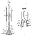
- the foot 1 is constituted by a square section tube terminated at its base by a latch 2 of the same section. This section facilitates immobilization of the foot in the orifice 5 of the floor and prevents parasitic rotational movements of the foot under the action of road reactions.
- the bolt is extended upwards by a cylindrical body 22 which carries a transverse pin 23 positioning the bolt 2 in height relative to the guide piece 24 secured to the foot 1.
- the operating handle 3 actuates the bolt 2 via a control rod 4.
- the rod 4 carries an immobilizing element 7.
- the immobilizing element consists of a square patch 8 with rounded tops carrying notches which can be engaged in complementary notches carried by the walls of the support housing 6 of the foot.
- This solution uses a tapping on the four inner faces of the box 6 with a square section, integral with the cross-member.
- the pad 8, integral with the rod 4 therefore carries a thread on each of its vertices to be screwed into the corresponding threads of the housing.
- a clearance is provided which is reduced when the threads are engaged.
- This play is obtained by a cam in the guide piece 24 under the pin 23.
- the maximum play corresponds to the unlocked position of the rod. This arrangement allows a height adjustment of the foot from 2 to 2 mm.
- the positive stop of the four vertices of the patch 8 on the housing is effected through four windows 9 made in the walls of the foot, the offset position of said windows, allows their edges to constitute stops for angular positioning of the pad 8 and consequently to define the lockingV unlocking positions D of the handle.
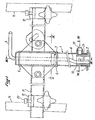
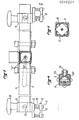
- the cross member 11 shown in more detail in Figures 1 and 2 consists of two cylindrical section tubes welded to the housing 6 whose free ends carry a clamp 12. Each collar is made integral with a tubular element 13 of the frame of the chair by means of clamping shells 15, 16 held together by means of screws 17.
- a stud 18 screwed into the clamping shell 15 crosses the cheeks of the collar 12 and receives a control button 19 whose manipulation in one direction or the other, ensures the tightening of all the shells 15, 16 against the collar 12 and the possible displacement of the latter on the tubular element of the cross member 11.
- Each cross member carries at its end a needle screw 20 which determines the axial setting and angle of the collar 12 and ensures correct angular positioning of the cross member in this collar.
- pivoting latch 2 the square section of which allows it to bear under the orifice 5 formed in the floor P of the vehicle following a rotation communicated by the handle 3 to rod 4.
- the body 22 also carries bores whose area cooperates with a known system of ball retainer 25 carried by the foot which allows the immobilization of the lock in the aforementioned locking and unlocking positions.
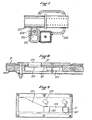
- Figures 8, 9 describe an exemplary embodiment of the hole in the floor.
- the orifices are formed from plates 26, 27 embedded in the floor P.
- the plates 26 or 27 consist of an upper part and a lower part.
- the upper plate 27 is pierced with an elongated opening 273 which converges towards a narrowed portion 274 whose dimensions are slightly larger than those of the latch.
- the lower plate 26 carries two openings 261, 261 ′ in correspondence with the opening 273.
- a shutter not shown can conceal one or two / aforementioned openings if these are not used and, electrical contactors 275 provide visualization to the dashboard of the locked or unlocked state of the foot.
- the control handle 3 can in principle occupy two positions illustrated in FIG. 2.
- Position "V” corresponds to the locking of the foot in the hole in the floor.
- Position "D" corresponds to unlocking.
- the initial positioning of the lock 2 on the rod 4 simultaneously allows the locking of the foot and its blocking in the housing 6 when the handle 3 occupies the "V" position.
- the movement of the foot is blocked in relation to the housing and the self-adjustment of the correct height of the foot in relation to the floor is taken into account, taking into account various use parameters such as: locations of the fixings of the device on the chair, tire inflation, user weight, floor characteristics.
- the setting of the insertion of the foot 1 into the orifice 5 is, moreover, automatically carried out by a stop 19 fixed on the rear part of the foot.
- This stop takes, in fact, support on the upper edge of the orifice so as to ensure the rotation of the latch 2 in contact with the underside of the orifice with a play of the order of 0.5mm and limits the stresses during sudden tipping and deceleration of the vehicle.
- the shape and orientation of the stop relative to the opening 273-274 requires an orientation to the chair.
- An additional stop can be provided at the front of the foot to limit its movements when braking the vehicle.
- the cross member 11 is adjusted by means of collars 12 or even telescopic ends as a function of the distance existing between the tubes 13 of the chair frame and the position of the foot relative to the floor is simultaneously adjusted.
- the immobilization of the collars is ensured by means of control buttons 19 and of screws 20 provided on the collars which ensure the immobilization thereof regardless of the spacing of the elements 13 of the frame of the chair.
- a screw-nut system shown in Figure 7 could ensure the adjustment and locking of the foot in a vertical position whatever the constructive characteristics of the chair.
- the nut 221 is fixed in a cage 222 attached to the cross member 223 and a maneuvering screw 224 positioned in a gusset 225 attached to the foot ensures the adjustment thereof.
- the user can therefore very easily mount the device on the chair. It suffices, in fact, to simultaneously screw the control button 19 and the stud 18 into the clamping shell 15 mounted on the frame of the chair at the appropriate height.
Landscapes
- Health & Medical Sciences (AREA)
- Public Health (AREA)
- Engineering & Computer Science (AREA)
- Life Sciences & Earth Sciences (AREA)
- Animal Behavior & Ethology (AREA)
- General Health & Medical Sciences (AREA)
- Veterinary Medicine (AREA)
- Transportation (AREA)
- Mechanical Engineering (AREA)
- Seats For Vehicles (AREA)
Applications Claiming Priority (2)
| Application Number | Priority Date | Filing Date | Title |
|---|---|---|---|
| FR8020895 | 1980-09-30 | ||
| FR8020895A FR2490956A1 (fr) | 1980-09-30 | 1980-09-30 | Dispositif d'immobilisation d'un cadre de fauteuil roulant pour handicapes physiques, notamment sur un plancher de vehicule |
Publications (1)
| Publication Number | Publication Date |
|---|---|
| EP0049201A1 true EP0049201A1 (fr) | 1982-04-07 |
Family
ID=9246402
Family Applications (1)
| Application Number | Title | Priority Date | Filing Date |
|---|---|---|---|
| EP81401490A Ceased EP0049201A1 (fr) | 1980-09-30 | 1981-09-25 | Dispositif d'immobilisation d'un cadre de fauteuil roulant pour handicapés physiques sur un plancher de véhicule |
Country Status (2)
| Country | Link |
|---|---|
| EP (1) | EP0049201A1 (online.php) |
| FR (1) | FR2490956A1 (online.php) |
Citations (4)
| Publication number | Priority date | Publication date | Assignee | Title |
|---|---|---|---|---|
| US3752265A (en) * | 1971-12-20 | 1973-08-14 | A Lyder | Wheel chair locking arrangement |
| US3955847A (en) * | 1975-02-03 | 1976-05-11 | Medi-Cab Inc. Of New York | Wheelchair hold down assembly |
| DE2533008A1 (de) * | 1975-07-23 | 1977-01-27 | Kaessbohrer Fahrzeug Karl | Vorrichtung zum arretieren von rollstuehlen in fahrzeugen zur personenbefoerderung |
| FR2383342A1 (fr) * | 1977-03-09 | 1978-10-06 | Heuliez Sa Louis | Dispositif de fixation, notamment pour fauteuil de personne handicapee |
-
1980
- 1980-09-30 FR FR8020895A patent/FR2490956A1/fr active Granted
-
1981
- 1981-09-25 EP EP81401490A patent/EP0049201A1/fr not_active Ceased
Patent Citations (4)
| Publication number | Priority date | Publication date | Assignee | Title |
|---|---|---|---|---|
| US3752265A (en) * | 1971-12-20 | 1973-08-14 | A Lyder | Wheel chair locking arrangement |
| US3955847A (en) * | 1975-02-03 | 1976-05-11 | Medi-Cab Inc. Of New York | Wheelchair hold down assembly |
| DE2533008A1 (de) * | 1975-07-23 | 1977-01-27 | Kaessbohrer Fahrzeug Karl | Vorrichtung zum arretieren von rollstuehlen in fahrzeugen zur personenbefoerderung |
| FR2383342A1 (fr) * | 1977-03-09 | 1978-10-06 | Heuliez Sa Louis | Dispositif de fixation, notamment pour fauteuil de personne handicapee |
Also Published As
| Publication number | Publication date |
|---|---|
| FR2490956B1 (online.php) | 1983-10-07 |
| FR2490956A1 (fr) | 1982-04-02 |
Similar Documents
| Publication | Publication Date | Title |
|---|---|---|
| CA2773512A1 (fr) | Base de fixation pour un siege automobile pour enfant | |
| EP0515275A1 (fr) | Plateau formant base tournante pour siège de véhicule | |
| CA2528463C (en) | Device for height adjustment of a child seat and telescopically adjustable foot support | |
| FR2533526A1 (fr) | Dispositif pour relier un mat a une planche a voile | |
| EP0225228A1 (fr) | Dispositif de réglage de la position d'un renvoi de sangle de ceinture de sécurité | |
| FR2745258A1 (fr) | Dispositif de maintien d'une bicyclette en stationnement comportant un antivol | |
| FR2724139A1 (fr) | Siege escamotable pour vehicules | |
| FR2490956A1 (fr) | Dispositif d'immobilisation d'un cadre de fauteuil roulant pour handicapes physiques, notamment sur un plancher de vehicule | |
| EP1359082B1 (fr) | Dispositif d'ajustement de position d'une colonne de direction réglable de véhicule automobile | |
| FR2841511A1 (fr) | Accoudoire reglable en hauteur, notamment pour siege de vehicule automobile | |
| FR2810929A1 (fr) | Dispositif d'assise pour vehicule | |
| FR2707567A1 (fr) | Siège pour véhicule automobile transformable en un siège pour jeune enfant. | |
| FR2480207A1 (fr) | Dispositif d'immobilisation d'un cadre de fauteuil roulant pour handicapes physiques notamment sur un plancher de vehicule | |
| EP0240416B1 (fr) | Dispositif de commande du déplacement relatif de deux organes, notamment pour siège de véhicule | |
| EP0633159B1 (fr) | Siège encastré pour le transport d'enfants dans un véhicule automobile | |
| FR2469315A3 (fr) | Appui-dos a appliquer contre le dossier d'un siege de vehicule | |
| KR200492736Y1 (ko) | 차량용 접이식 자전거 거치장치 | |
| EP0022039A1 (fr) | Siège réglable | |
| FR2545426A1 (fr) | Dispositif de reglage d'inclinaison du coussin d'un siege de vehicule automobile | |
| FR2697785A1 (fr) | Dispositif de siège secondaire pour passager enfant intégré dans un siège principal de véhicule automobile. | |
| FR2706827A1 (en) | Safety car seat for a child | |
| FR2780259A1 (fr) | Crochet de suspension de tableau d'art | |
| CN121926781A (zh) | 调整机构及助行器 | |
| EP0519532A1 (fr) | Support d'étau pivotant et orientable | |
| FR3151991A1 (fr) | Siège passager de véhicule automobile comprenant un siège enfant intégré |
Legal Events
| Date | Code | Title | Description |
|---|---|---|---|
| PUAI | Public reference made under article 153(3) epc to a published international application that has entered the european phase |
Free format text: ORIGINAL CODE: 0009012 |
|
| 17P | Request for examination filed |
Effective date: 19810930 |
|
| AK | Designated contracting states |
Designated state(s): AT BE CH DE GB IT LU NL SE |
|
| STAA | Information on the status of an ep patent application or granted ep patent |
Free format text: STATUS: THE APPLICATION HAS BEEN REFUSED |
|
| 18R | Application refused |
Effective date: 19840625 |
|
| RIN1 | Information on inventor provided before grant (corrected) |
Inventor name: EMMANUEL, REMY |