EP0049085A1 - Hydraulic wheel cylinder assemblies and drum brakes incorporating same - Google Patents
Hydraulic wheel cylinder assemblies and drum brakes incorporating same Download PDFInfo
- Publication number
- EP0049085A1 EP0049085A1 EP81304341A EP81304341A EP0049085A1 EP 0049085 A1 EP0049085 A1 EP 0049085A1 EP 81304341 A EP81304341 A EP 81304341A EP 81304341 A EP81304341 A EP 81304341A EP 0049085 A1 EP0049085 A1 EP 0049085A1
- Authority
- EP
- European Patent Office
- Prior art keywords
- wheel cylinder
- cylinder assembly
- piston
- assembly
- pair
- Prior art date
- Legal status (The legal status is an assumption and is not a legal conclusion. Google has not performed a legal analysis and makes no representation as to the accuracy of the status listed.)
- Granted
Links
- 230000000712 assembly Effects 0.000 title claims abstract description 13
- 238000000429 assembly Methods 0.000 title claims abstract description 13
- 230000006835 compression Effects 0.000 claims abstract 2
- 238000007906 compression Methods 0.000 claims abstract 2
- 230000000694 effects Effects 0.000 claims description 2
- 230000000717 retained effect Effects 0.000 description 2
- 230000002301 combined effect Effects 0.000 description 1
- 230000005484 gravity Effects 0.000 description 1
- 238000009434 installation Methods 0.000 description 1
Images

Classifications
-
- F—MECHANICAL ENGINEERING; LIGHTING; HEATING; WEAPONS; BLASTING
- F16—ENGINEERING ELEMENTS AND UNITS; GENERAL MEASURES FOR PRODUCING AND MAINTAINING EFFECTIVE FUNCTIONING OF MACHINES OR INSTALLATIONS; THERMAL INSULATION IN GENERAL
- F16D—COUPLINGS FOR TRANSMITTING ROTATION; CLUTCHES; BRAKES
- F16D65/00—Parts or details
- F16D65/38—Slack adjusters
- F16D65/40—Slack adjusters mechanical
- F16D65/52—Slack adjusters mechanical self-acting in one direction for adjusting excessive play
- F16D65/56—Slack adjusters mechanical self-acting in one direction for adjusting excessive play with screw-thread and nut
- F16D65/561—Slack adjusters mechanical self-acting in one direction for adjusting excessive play with screw-thread and nut for mounting within the confines of a drum brake
- F16D65/562—Slack adjusters mechanical self-acting in one direction for adjusting excessive play with screw-thread and nut for mounting within the confines of a drum brake arranged between service brake actuator and braking member, and subjected to service brake force
-
- F—MECHANICAL ENGINEERING; LIGHTING; HEATING; WEAPONS; BLASTING
- F16—ENGINEERING ELEMENTS AND UNITS; GENERAL MEASURES FOR PRODUCING AND MAINTAINING EFFECTIVE FUNCTIONING OF MACHINES OR INSTALLATIONS; THERMAL INSULATION IN GENERAL
- F16D—COUPLINGS FOR TRANSMITTING ROTATION; CLUTCHES; BRAKES
- F16D2125/00—Components of actuators
- F16D2125/18—Mechanical mechanisms
- F16D2125/58—Mechanical mechanisms transmitting linear movement
- F16D2125/66—Wedges
Definitions
- the invention relates to Hydraulic Wheel Cylinder Assembliesand internal shoe drum brakes, particularly brakes of the kind in which the wheel cylinder assembly is interposed between one pair of adjacent ends of a pair of brake shoes and acts as a spacing strut for said ends and a mechanical expander and fixed abutment means are interposed between the other pair of adjacent ends of the shoes.
- a drum brake of the kind referred to is described in British Patent Specification No. 1 513 740. It has Leading-and-Trailing shoe performance in the hydraulic actuating mode, giving stable and consistent performance in both directions of drum rotation, with Duo-Servo shoe performance in the mechanical mode, giving a high torque restraint in both directions for parking purposes.
- the wheel cylinder assembly shown in this patent specification performs satisfactorily it has a disadvantage concerning the installation of the brake on a motor vehicle. Space and other restraints sometimes require the brake to be mounted with the shoes disposed either side of the horizontal centreline. In this arrangement the weight of the shoes tends to cause the wheel cylinder pistons and the shoes to fall under the combined effects of vibration and gravity, despite the presence of friction created by the shoe hold-down springs, and so cause brake drag.
- a hydraulic wheel cylinder assembly for an internal wheel cylinder assembly shoe drum brake,the/comprising a cylinder body having a through bore therein, a pair of piston assemblies slidable in said bore and an inlet port in the body which opens into the bore for supplying hydraulic pressure to urge the piston assemblies away from each other, each piston assembly having an automatically adjustable variable length tappet assembly for transmitting a thrust to an adjacent brake shoe and comprising a rotatable screw-threaded component interengaged with a non-rotatable screw-threaded component associated with each tappet and a one-way drive mechanism/assembly to effect rotation of the rotatable screw-threaded component in the direction to increase the length of the tappet assembly in response to excessive movement of the respective piston assembly in the bore, the one-way drive mechanism including a driven member which is rotationally fast with the rotatable screw-threaded component but axially movable relative thereto against a spring, the driven member comprising stop means for
- an internal shoe drum brake comprising a hydraulic wheel cylinder assembly interposed between one pair of adjacent ends of a pair of brake shoes and a mechanical expander and fixed abutment means interposed between the other pair of adjacent ends of the shoes, wherein the wheel cylinder assembly is a wheel cylinder assembly according to said one aspect of the invention.
- the drum brake shown in the drawings includes a backplate 11 and a pair of brake shoes 12 and 13 spaced slightly from the backplate by adjustable steady pins 14.
- the usual hold down spring assemblies 15 are provided.
- a mechanical expander 16 (Fig. 3) which comprises a wedge 17 operating between rollers 18 carried by tappets 19.
- the tappets are a sliding fit in the expander body 21 and each has a head which provides an abutting shoulder with the body 21 to react the load of the usual pull-off springs 22 and also brake drag loads as will be described later.
- the wedge 17 is connected to a pull-rod 23 of a spring actuator assembly 24.
- a diaphragm 25 subject to air pressure at port 26 normally keeps the expander 16 in the inoperative state shown in Fi g. 3 against the load of coil springs 27 which act through a dished plate 28 against a cup-shaped plate 29.
- the springs 27 react against a housing 31 which is retained on a support tube 32.
- the air pressure at port 26 is released the springs 27 act through plate 28 onto a head 33 on the pull-rod 23, pulling the wedge 17 to urge the tappets 19 apart.
- a hydraulic wheel cylinder assembly 34 is between the other pair of adjacent ends of the brake shoes 12 and 13, being shown in more detail in Fig. 4. It comprises a cylinder body 35 having a through bore 36 in which are slidable a pair of piston assemblies 37 and 38. Since the piston assemblies are identical, only one, 37, will be described in detail.
- Piston assembly 37 includes a piston body 39 which has a groove for a rubber seal 41 and a slot 42 which engages two flats on a generally cylindrical pawl peg 43.
- a coil spring 44 retained by a screw cap 45 biasses the pawl peg 43 into engagement with helical ratchet teeth on a sleeve component 46 which is received in a bore in the piston body 39.
- These ratchet teeth are in the form of a multi-start fine pitch buttress screw thread and the teeth on the payl peg 43 have a similar form.
- the pawl peg 43 has a circular head 47 which is received in the base of the threaded recess for the screw cap 45 and which is eccentric to the axis of the cylindrical portion to ensure correct assembly.
- a screw threaded nut component 48 is a sliding fit within sleeve component 46, being interengaged with a screw-threaded tappet 49 which is non-rotatable by virtue of engagement of the adjacent end of brake shoe 12 in a slot in the head of the tappet.
- the sleeve member 46 is rotationally fast with the nut component 48 by virtue of dog teeth formed on an inwardly directed flange 51, the teeth engaging in longitudinal grooves 52 in the nut component 48.
- a coil spring 53 biasses the flange 51 into engagement with a snap-ring or circlip 54 held in a groove in the nut component 48.
- the piston assemblies 37 and 38 are in abutment with each other, being biassed by the pull-off springs 22, and there is a small clearance between the end face of the cylinder body 35 and radial flange 55 on the sleeve component 46.
- This flange 55 co-operates with the adjacent end face of the cylinder 35 to act as stop means for limiting movement of the sleeve component in the direction of piston assembly 38.
- An inlet port 56 is provided for supplying hydraulic pressure under the control of the driver of a vehicle to which the brake is fitted.
- the brake When installed on a vehicle the brake is normally fitted with the axis of the wheel cylinder 34 vertical, so that the brake shoes 12 and 13 are in fact disposed either side of the horizontal centre line of Fig. 1 if the drawing is rotated through 90°.
- hydraulic pressure is supplied to inlet port 56 of the wheel cylinder 34 to move the piston assemblies 37 and 38 away from each other to apply brake shoes 12 and 13 to an associated brake drum (not shown).
- the expander body 16 reacts the shoe tip loads on the heads of tappets 19 as previously described so that the brake functions as a leading-and-trailing shoe brake for both directions of drum rotation.
- Spring 53 is preloaded to form a spring connection between the sleeve component 46 and the nut component 48 which allows relative axial movement in one direction such that the nut component 48 can move in the direction of the piston assembly 38 when the sleeve .component is arrested by flange 55 striking the cylinder body 35.
- This serves two purposes.
- flange 55 contacts the end face of the cylinder body and spring 53 acts on the nut component 48 and tappet 49 to help support the weight of shoe 12 and, by the tension of the pull-off springs 22, supports shoe 13 also.
- the shoes 12 and 13 are also supported by friction created by the hold-down spring assemblies 15.
- a one-way drive mechanism includes the sleeve component 46 acting as the driven member and the pawl peg 43 acting as the driving member, the ratchet teeth on the sleeve component 46 and the pawl teeth on the pawl peg 43 being arranged so that when the piston assembly 37 is moved to the right of Fig. 4, eg. on hydraulic operation of the wheel cylinder, the pawl teeth ride up the ratchet teeth. If the shoe to drum clearance is small then the crests of the ratchet teeth will not reach the crests of the pawl teeth and the parts return to their original positions when hydraulic pressure is released.
- the ratchet teeth will ride over the crests of the pawl teeth.
- the pawl teeth act on the ratchet teeth to tend to turn the sleeve component 46 (and thus the nut component 48) in the direction to move the tappet 49 outwards and thus increase the length of the assembly.
- the spring 53 acts to absorb the release movement of the shoe 12 by becoming compressed while the tappet 49, nut component 48 and piston body 39 continue to return to their positions as shown in Fig. 4 if the friction in the screw-threads of the nut component 48 and the tappet should be too high and so prevent turning.
Landscapes
- Engineering & Computer Science (AREA)
- General Engineering & Computer Science (AREA)
- Mechanical Engineering (AREA)
- Braking Arrangements (AREA)
Abstract
Description
- The invention relates to Hydraulic Wheel Cylinder Assembliesand internal shoe drum brakes, particularly brakes of the kind in which the wheel cylinder assembly is interposed between one pair of adjacent ends of a pair of brake shoes and acts as a spacing strut for said ends and a mechanical expander and fixed abutment means are interposed between the other pair of adjacent ends of the shoes.
- A drum brake of the kind referred to is described in British Patent Specification No. 1 513 740. It has Leading-and-Trailing shoe performance in the hydraulic actuating mode, giving stable and consistent performance in both directions of drum rotation, with Duo-Servo shoe performance in the mechanical mode, giving a high torque restraint in both directions for parking purposes. However, whilst the wheel cylinder assembly shown in this patent specification performs satisfactorily it has a disadvantage concerning the installation of the brake on a motor vehicle. Space and other restraints sometimes require the brake to be mounted with the shoes disposed either side of the horizontal centreline. In this arrangement the weight of the shoes tends to cause the wheel cylinder pistons and the shoes to fall under the combined effects of vibration and gravity, despite the presence of friction created by the shoe hold-down springs, and so cause brake drag.
- one aspect of According to/the invention there is provided a hydraulic wheel cylinder assembly for an internal wheel cylinder assembly shoe drum brake,the/comprising a cylinder body having a through bore therein, a pair of piston assemblies slidable in said bore and an inlet port in the body which opens into the bore for supplying hydraulic pressure to urge the piston assemblies away from each other, each piston assembly having an automatically adjustable variable length tappet assembly for transmitting a thrust to an adjacent brake shoe and comprising a rotatable screw-threaded component interengaged with a non-rotatable screw-threaded component associated with each tappet and a one-way drive mechanism/assembly to effect rotation of the rotatable screw-threaded component in the direction to increase the length of the tappet assembly in response to excessive movement of the respective piston assembly in the bore, the one-way drive mechanism including a driven member which is rotationally fast with the rotatable screw-threaded component but axially movable relative thereto against a spring, the driven member comprising stop means for limiting movement of the driven member in the direction of the other piston assembly and the spring being arranged to yield during continuing movement of the screw-threaded components in said direction.
- According to another aspect of the invention there is provided an internal shoe drum brake comprising a hydraulic wheel cylinder assembly interposed between one pair of adjacent ends of a pair of brake shoes and a mechanical expander and fixed abutment means interposed between the other pair of adjacent ends of the shoes, wherein the wheel cylinder assembly is a wheel cylinder assembly according to said one aspect of the invention.
- One embodiment of the invention will now be described by way of example and with reference to the accompanying drawings, of which:-
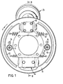
- Fig. 1 is an elevation of an internal shoe drum brake assembly incorporating a hydraulic wheel cylinder assembly according to the invention;
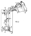
- Fig. 2 is a cross-sectional elevation on the line II-II in Fig. 1;
- Fig. 3 is a cross-section on the line III-III in Fig. 2 drawn to a larger scale; and
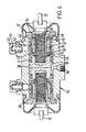
- Fig. 4 is a cross-section on the line IV-IV in Fig. 2 drawn to the same scale as Fig. 3.
- The drum brake shown in the drawings includes a
backplate 11 and a pair ofbrake shoes spring assemblies 15 are provided. - Between one pair of adjacent ends of the
brake shoes wedge 17 operating betweenrollers 18 carried bytappets 19. The tappets are a sliding fit in the expander body 21 and each has a head which provides an abutting shoulder with the body 21 to react the load of the usual pull-offsprings 22 and also brake drag loads as will be described later. - The
wedge 17 is connected to a pull-rod 23 of aspring actuator assembly 24. Adiaphragm 25 subject to air pressure atport 26 normally keeps theexpander 16 in the inoperative state shown in Fi g. 3 against the load ofcoil springs 27 which act through adished plate 28 against a cup-shaped plate 29. Thesprings 27 react against ahousing 31 which is retained on asupport tube 32. When the air pressure atport 26 is released thesprings 27 act throughplate 28 onto ahead 33 on the pull-rod 23, pulling thewedge 17 to urge thetappets 19 apart. - A hydraulic
wheel cylinder assembly 34 according to the invention is between the other pair of adjacent ends of thebrake shoes cylinder body 35 having athrough bore 36 in which are slidable a pair ofpiston assemblies - Piston
assembly 37 includes apiston body 39 which has a groove for arubber seal 41 and a slot 42 which engages two flats on a generallycylindrical pawl peg 43. Acoil spring 44 retained by ascrew cap 45 biasses thepawl peg 43 into engagement with helical ratchet teeth on asleeve component 46 which is received in a bore in thepiston body 39. These ratchet teeth are in the form of a multi-start fine pitch buttress screw thread and the teeth on thepayl peg 43 have a similar form. Thepawl peg 43 has acircular head 47 which is received in the base of the threaded recess for thescrew cap 45 and which is eccentric to the axis of the cylindrical portion to ensure correct assembly. - A screw threaded
nut component 48 is a sliding fit withinsleeve component 46, being interengaged with a screw-threadedtappet 49 which is non-rotatable by virtue of engagement of the adjacent end ofbrake shoe 12 in a slot in the head of the tappet. Thesleeve member 46 is rotationally fast with thenut component 48 by virtue of dog teeth formed on an inwardly directed flange 51, the teeth engaging inlongitudinal grooves 52 in thenut component 48. A coil spring 53 biasses the flange 51 into engagement with a snap-ring orcirclip 54 held in a groove in thenut component 48. - As shown in Fig. 4 the piston assemblies 37 and 38 are in abutment with each other, being biassed by the pull-off
springs 22, and there is a small clearance between the end face of thecylinder body 35 andradial flange 55 on thesleeve component 46. Thisflange 55 co-operates with the adjacent end face of thecylinder 35 to act as stop means for limiting movement of the sleeve component in the direction ofpiston assembly 38. Aninlet port 56 is provided for supplying hydraulic pressure under the control of the driver of a vehicle to which the brake is fitted. - When installed on a vehicle the brake is normally fitted with the axis of the
wheel cylinder 34 vertical, so that thebrake shoes inlet port 56 of thewheel cylinder 34 to move thepiston assemblies brake shoes expander body 16 reacts the shoe tip loads on the heads oftappets 19 as previously described so that the brake functions as a leading-and-trailing shoe brake for both directions of drum rotation. - For parking, or in emergencies, air is released from
port 26 in thespring actuator 24 to allowsprings 27 to act on thewedge 17. For forwards drum rotation, as indicated by arrow F (Fig. 1), only the tappet 19 acting onshoe 13 moves under the wedging action, the other tappet 19 acting onshoe 12 having to react a greater load than is applied by thewedge 17. This is because thepiston assembly 38 transmits the drag load from the trailing end ofshoe 13 topiston assembly 37 which applies the load to the leading end ofshoe 12 in a manner typical of a duo-servo brake. For reverse brake drum rotation the tappet 19 acting onshoe 12 moves and the tappet acting onshoe 13 provides the reaction. - During reverse-rotation duo-servo operation of the brake, the drag forces of
shoe 12 act ontappet assembly 37 to movetappet assembly 38 to applyshoe 13, ie. towards the left of Fig. 4. However, thesleeve component 46 is restrained byflange 55 so that spring 53 is compressed during such movement. - Spring 53 is preloaded to form a spring connection between the
sleeve component 46 and thenut component 48 which allows relative axial movement in one direction such that thenut component 48 can move in the direction of thepiston assembly 38 when the sleeve .component is arrested byflange 55 striking thecylinder body 35. This serves two purposes. When the brake is installed as described above and, for example,brake shoe 12 is uppermost, thenflange 55 contacts the end face of the cylinder body and spring 53 acts on thenut component 48 and tappet 49 to help support the weight ofshoe 12 and, by the tension of the pull-offsprings 22, supportsshoe 13 also. Theshoes down spring assemblies 15. - The other purpose of spring 53 is in connection with the automatic adjustment of the variable length tappet assembly which comprises the
tappet 49 andnut component 48. A one-way drive mechanism includes thesleeve component 46 acting as the driven member and thepawl peg 43 acting as the driving member, the ratchet teeth on thesleeve component 46 and the pawl teeth on thepawl peg 43 being arranged so that when thepiston assembly 37 is moved to the right of Fig. 4, eg. on hydraulic operation of the wheel cylinder, the pawl teeth ride up the ratchet teeth. If the shoe to drum clearance is small then the crests of the ratchet teeth will not reach the crests of the pawl teeth and the parts return to their original positions when hydraulic pressure is released. If, however, the clearance is excessive then the ratchet teeth will ride over the crests of the pawl teeth. When the piston assembly returns, the pawl teeth act on the ratchet teeth to tend to turn the sleeve component 46 (and thus the nut component 48) in the direction to move thetappet 49 outwards and thus increase the length of the assembly. The spring 53 acts to absorb the release movement of theshoe 12 by becoming compressed while thetappet 49,nut component 48 andpiston body 39 continue to return to their positions as shown in Fig. 4 if the friction in the screw-threads of thenut component 48 and the tappet should be too high and so prevent turning. This is particularly likely when the brake is applied hydraulically when coming to a halt on an upwards slope and thespring actuator 24 is brought into action for parking, since the torque reaction of the brake is reversed whilst in the duo-servo mode. This means that the load transmitted by thepiston assemblies piston assembly 37 has to move from one extreme of travel in which it appliesshoe 12 as a leading shoe to the other extreme in which it reacts the drag load ofshoe 12 and acts on theother assembly 38 to applyshoe 13.
Claims (7)
Applications Claiming Priority (2)
| Application Number | Priority Date | Filing Date | Title |
|---|---|---|---|
| GB8031307 | 1980-09-27 | ||
| GB8031307 | 1980-09-27 |
Publications (2)
| Publication Number | Publication Date |
|---|---|
| EP0049085A1 true EP0049085A1 (en) | 1982-04-07 |
| EP0049085B1 EP0049085B1 (en) | 1985-05-29 |
Family
ID=10516347
Family Applications (1)
| Application Number | Title | Priority Date | Filing Date |
|---|---|---|---|
| EP81304341A Expired EP0049085B1 (en) | 1980-09-27 | 1981-09-22 | Hydraulic wheel cylinder assemblies and drum brakes incorporating same |
Country Status (4)
| Country | Link |
|---|---|
| US (1) | US4416356A (en) |
| EP (1) | EP0049085B1 (en) |
| JP (1) | JPS5786639A (en) |
| DE (1) | DE3170730D1 (en) |
Cited By (2)
| Publication number | Priority date | Publication date | Assignee | Title |
|---|---|---|---|---|
| FR2532020A1 (en) * | 1982-08-18 | 1984-02-24 | Daimler Benz Ag | APPARATUS FOR RETRIEVING PLAY AND CENTERING MOUNTED ON THE SLIDING CLOSURE DEVICE OF A SERVO BRAKE WITH INTERNAL JAWS, IN PARTICULAR FOR MOTOR VEHICLES |
| US5806635A (en) * | 1995-05-24 | 1998-09-15 | Hyundai Motor Company, Ltd. | Friction brake system for a vehicle |
Families Citing this family (14)
| Publication number | Priority date | Publication date | Assignee | Title |
|---|---|---|---|---|
| GB8324942D0 (en) * | 1983-09-17 | 1983-10-19 | Lucas Ind Plc | Actuator assemblies for vehicle brakes |
| US4815571A (en) * | 1985-07-23 | 1989-03-28 | Lucas Industries Public Limited Company | Automatic adjuster |
| JPS63285341A (en) * | 1987-05-14 | 1988-11-22 | Akebono Brake Ind Co Ltd | Device for automatically adjusting gap of brake |
| US4867281A (en) * | 1988-09-27 | 1989-09-19 | Rockwell International Corporation | Self-adjusting brake actuator |
| US5823636A (en) * | 1997-02-24 | 1998-10-20 | General Motors Corporation | Vehicle braking system |
| US6435322B1 (en) * | 1999-05-07 | 2002-08-20 | Nisshinbo Industries, Inc. | Duo two leading type drum brake device |
| JP2007132393A (en) * | 2005-11-09 | 2007-05-31 | Honda Motor Co Ltd | Brake device for vehicle |
| CN100338371C (en) * | 2005-12-22 | 2007-09-19 | 江苏恒力制动器制造有限公司 | Wedge type mechanism capable of automatic regulating brake gap |
| ITMI20061513A1 (en) * | 2006-07-31 | 2008-02-01 | Poli Costruzione Materiali Trazione Spa | COMPACT BRAKING DISC UNIT FOR RAIL VEHICLES |
| CN107054334B (en) * | 2011-03-31 | 2019-07-09 | 株式会社爱德克斯 | Electric parking and braking device |
| DE102011088847B4 (en) | 2011-12-16 | 2016-08-04 | Saf-Holland Gmbh | Brake system of a drum brake |
| DE102014013868B4 (en) * | 2014-09-24 | 2019-02-28 | Knott Gmbh | Actuation device for an internal shoe brake with automatic adjustment device |
| US10125830B2 (en) * | 2017-04-06 | 2018-11-13 | FEV Europe GmbH | Wedge actuated drum-in-hat parking brake |
| IL257535B (en) | 2018-02-14 | 2020-01-30 | N3 Coat Ltd | Benzophenone photoinitiators for polyolefins |
Citations (4)
| Publication number | Priority date | Publication date | Assignee | Title |
|---|---|---|---|---|
| FR1292588A (en) * | 1961-06-17 | 1962-05-04 | Rockwell Standard Co | Automatic vehicle brake adjuster |
| DE1902597A1 (en) * | 1968-01-24 | 1969-12-04 | Perrot Bremse Gmbh Deutsche | Automatic adjustment and centering device for servo brakes |
| GB1412151A (en) * | 1972-11-09 | 1975-10-29 | Gilling Ltd | Extensible strut adjuster with overload prevention device |
| GB1513740A (en) * | 1975-12-18 | 1978-06-07 | Automotive Prod Co Ltd | Brake actuating cylinder with autoadjuster |
Family Cites Families (5)
| Publication number | Priority date | Publication date | Assignee | Title |
|---|---|---|---|---|
| US3977500A (en) * | 1972-05-04 | 1976-08-31 | Girling Limited | Shoe drum brakes for vehicles |
| JPS5747479Y2 (en) * | 1974-02-26 | 1982-10-19 | ||
| GB1476798A (en) * | 1974-11-15 | 1977-06-16 | Girling Ltd | Actuator assemblies for vehicle brakes |
| JPS5815692Y2 (en) * | 1975-12-23 | 1983-03-30 | オウトモウチブ プロダクツ リミテツド | Brake your own cylinder |
| GB2062784B (en) * | 1979-10-10 | 1983-08-10 | Lucas Industries Ltd | Automatic slack adjusters for vehicle shoedrum brakes |
-
1981
- 1981-09-16 US US06/302,530 patent/US4416356A/en not_active Expired - Fee Related
- 1981-09-22 EP EP81304341A patent/EP0049085B1/en not_active Expired
- 1981-09-22 DE DE8181304341T patent/DE3170730D1/en not_active Expired
- 1981-09-25 JP JP56151934A patent/JPS5786639A/en active Granted
Patent Citations (5)
| Publication number | Priority date | Publication date | Assignee | Title |
|---|---|---|---|---|
| FR1292588A (en) * | 1961-06-17 | 1962-05-04 | Rockwell Standard Co | Automatic vehicle brake adjuster |
| DE1902597A1 (en) * | 1968-01-24 | 1969-12-04 | Perrot Bremse Gmbh Deutsche | Automatic adjustment and centering device for servo brakes |
| DE1903560A1 (en) * | 1968-01-24 | 1970-01-29 | Perrot Bremse Gmbh Deutsche | Automatic adjustment device for friction brakes |
| GB1412151A (en) * | 1972-11-09 | 1975-10-29 | Gilling Ltd | Extensible strut adjuster with overload prevention device |
| GB1513740A (en) * | 1975-12-18 | 1978-06-07 | Automotive Prod Co Ltd | Brake actuating cylinder with autoadjuster |
Cited By (3)
| Publication number | Priority date | Publication date | Assignee | Title |
|---|---|---|---|---|
| FR2532020A1 (en) * | 1982-08-18 | 1984-02-24 | Daimler Benz Ag | APPARATUS FOR RETRIEVING PLAY AND CENTERING MOUNTED ON THE SLIDING CLOSURE DEVICE OF A SERVO BRAKE WITH INTERNAL JAWS, IN PARTICULAR FOR MOTOR VEHICLES |
| GB2125496A (en) * | 1982-08-18 | 1984-03-07 | Daimler Benz Ag | Brake adjustment device |
| US5806635A (en) * | 1995-05-24 | 1998-09-15 | Hyundai Motor Company, Ltd. | Friction brake system for a vehicle |
Also Published As
| Publication number | Publication date |
|---|---|
| EP0049085B1 (en) | 1985-05-29 |
| US4416356A (en) | 1983-11-22 |
| DE3170730D1 (en) | 1985-07-04 |
| JPS5786639A (en) | 1982-05-29 |
| JPH026932B2 (en) | 1990-02-14 |
Similar Documents
| Publication | Publication Date | Title |
|---|---|---|
| EP0049085B1 (en) | Hydraulic wheel cylinder assemblies and drum brakes incorporating same | |
| US4022300A (en) | Mechanical disc brake | |
| GB2332027A (en) | Wear-adjusting device for a disc brake for a motor vehicle | |
| US3995722A (en) | Fail-safe disc brake having a slack adjuster mechanism | |
| PL84821B1 (en) | ||
| US4491203A (en) | Power screw disc brake with internal automatic slack adjuster | |
| CA2604245A1 (en) | Adjusting apparatus for a pneumatically actuated disc brake | |
| US3848705A (en) | Application adjuster for disc brake | |
| JPS5847578B2 (en) | Sealing brake motor cylinder | |
| US4537293A (en) | Hydraulic cylinder assemblies | |
| US3583532A (en) | Automatic adjusting means for internal shoe drum brakes | |
| AU717900B2 (en) | Play adjustment | |
| US3797613A (en) | Automatic adjuster with limiting device | |
| US7721854B1 (en) | Assured running clearance caliper | |
| JPS5928783B2 (en) | Vehicle brake actuator | |
| GB2102088A (en) | Disc brakes | |
| US3378109A (en) | Disc brake assembly | |
| US6460660B1 (en) | Parking brake for drum type brakes with electronic lining wear sensor and adjuster | |
| SU713541A3 (en) | Disc brake | |
| US3726367A (en) | Combined service and parking brake | |
| US3977500A (en) | Shoe drum brakes for vehicles | |
| US4294335A (en) | Device for automatically adjusting a braking clearance for a disc brake | |
| US6386339B1 (en) | Automatic adjuster for spring applied mechanisms | |
| US3482662A (en) | Air brake cylinder with slack adjuster | |
| JPS59110928A (en) | Brake automatic regulator |
Legal Events
| Date | Code | Title | Description |
|---|---|---|---|
| PUAI | Public reference made under article 153(3) epc to a published international application that has entered the european phase |
Free format text: ORIGINAL CODE: 0009012 |
|
| AK | Designated contracting states |
Designated state(s): BE DE FR GB IT SE |
|
| RAP1 | Party data changed (applicant data changed or rights of an application transferred) |
Owner name: AUTOMOTIVE PRODUCTS PUBLIC LIMITED COMPANY |
|
| 17P | Request for examination filed |
Effective date: 19820615 |
|
| RBV | Designated contracting states (corrected) |
Designated state(s): DE FR GB IT |
|
| ITF | It: translation for a ep patent filed | ||
| GRAA | (expected) grant |
Free format text: ORIGINAL CODE: 0009210 |
|
| AK | Designated contracting states |
Designated state(s): DE FR GB IT |
|
| REF | Corresponds to: |
Ref document number: 3170730 Country of ref document: DE Date of ref document: 19850704 |
|
| ET | Fr: translation filed | ||
| PLBE | No opposition filed within time limit |
Free format text: ORIGINAL CODE: 0009261 |
|
| STAA | Information on the status of an ep patent application or granted ep patent |
Free format text: STATUS: NO OPPOSITION FILED WITHIN TIME LIMIT |
|
| 26N | No opposition filed | ||
| PG25 | Lapsed in a contracting state [announced via postgrant information from national office to epo] |
Ref country code: DE Effective date: 19880601 |
|
| GBPC | Gb: european patent ceased through non-payment of renewal fee | ||
| PG25 | Lapsed in a contracting state [announced via postgrant information from national office to epo] |
Ref country code: GB Free format text: LAPSE BECAUSE OF NON-PAYMENT OF DUE FEES Effective date: 19881118 |
|
| PGFP | Annual fee paid to national office [announced via postgrant information from national office to epo] |
Ref country code: FR Payment date: 19890807 Year of fee payment: 9 |
|
| PG25 | Lapsed in a contracting state [announced via postgrant information from national office to epo] |
Ref country code: FR Effective date: 19910530 |
|
| REG | Reference to a national code |
Ref country code: FR Ref legal event code: ST |