EP0049079B1 - Verfahren zum Rundbiegen von Blechen - Google Patents
Verfahren zum Rundbiegen von Blechen Download PDFInfo
- Publication number
- EP0049079B1 EP0049079B1 EP81304316A EP81304316A EP0049079B1 EP 0049079 B1 EP0049079 B1 EP 0049079B1 EP 81304316 A EP81304316 A EP 81304316A EP 81304316 A EP81304316 A EP 81304316A EP 0049079 B1 EP0049079 B1 EP 0049079B1
- Authority
- EP
- European Patent Office
- Prior art keywords
- plate
- mandrel
- gripper
- edge
- trailing edge
- Prior art date
- Legal status (The legal status is an assumption and is not a legal conclusion. Google has not performed a legal analysis and makes no representation as to the accuracy of the status listed.)
- Expired
Links
- 238000000034 method Methods 0.000 title claims abstract description 8
- 238000005096 rolling process Methods 0.000 title claims abstract description 4
- 230000015572 biosynthetic process Effects 0.000 claims description 2
- 238000005452 bending Methods 0.000 description 6
- 229910000831 Steel Inorganic materials 0.000 description 2
- 239000010959 steel Substances 0.000 description 2
- 230000000694 effects Effects 0.000 description 1
Images
Classifications
-
- B—PERFORMING OPERATIONS; TRANSPORTING
- B21—MECHANICAL METAL-WORKING WITHOUT ESSENTIALLY REMOVING MATERIAL; PUNCHING METAL
- B21D—WORKING OR PROCESSING OF SHEET METAL OR METAL TUBES, RODS OR PROFILES WITHOUT ESSENTIALLY REMOVING MATERIAL; PUNCHING METAL
- B21D5/00—Bending sheet metal along straight lines, e.g. to form simple curves
- B21D5/06—Bending sheet metal along straight lines, e.g. to form simple curves by drawing procedure making use of dies or forming-rollers, e.g. making profiles
- B21D5/10—Bending sheet metal along straight lines, e.g. to form simple curves by drawing procedure making use of dies or forming-rollers, e.g. making profiles for making tubes
-
- B—PERFORMING OPERATIONS; TRANSPORTING
- B21—MECHANICAL METAL-WORKING WITHOUT ESSENTIALLY REMOVING MATERIAL; PUNCHING METAL
- B21D—WORKING OR PROCESSING OF SHEET METAL OR METAL TUBES, RODS OR PROFILES WITHOUT ESSENTIALLY REMOVING MATERIAL; PUNCHING METAL
- B21D5/00—Bending sheet metal along straight lines, e.g. to form simple curves
- B21D5/14—Bending sheet metal along straight lines, e.g. to form simple curves by passing between rollers
- B21D5/143—Bending sheet metal along straight lines, e.g. to form simple curves by passing between rollers making use of a mandrel
Definitions
- This invention relates to plate bending methods and particularly to a machine as described in AU-A-463,345.
- a method of rolling plate to form a cylindrical article which comprises gripping a leading edge of a length of plate with a mandrel gripper so that the plate is tangential to the mandrel from the said edge; rotating the mandrel while engaging the remainder of the plate against the mandrel by pressure means to move the plate to curve a forward part of the plate about the mandrel into a semi-cylindrical shape; subsequently further advancing the plate until the rearward part of the plate and its trailing edge pass beyond contact with the mandrel; and then gripping the said trailing edge with the mandrel gripper and turning the mandrel again to curve the rearward part of the plate about the mandrel into a semi-cylindrical shape so that said forward and rearward parts together complete the formation of a cylinder.
- the aim of the present invention is modify and improve the therein disclosed method thereby ensuring that the edge of the plate is properly gripped by the rib on the mandrel. More specifically, it is the aim of the invention to provide bending for plates of greater thickness than possible hitherto.
- the present invention is characterised by the steps of forming a recess in the leading and trailing edge portions of the plate before curving the plate; selecting a plate thickness greater than said recessed edge portions; serially gripping said recessed leading and trailing edge portions with said mandrel gripper so that the unrecessed plate thickness is substantially the same as the maximum radial dimension of the mandrel gripper to thereby form a cylinder.
- the mandrel is turned in a direction towards the edge of the plate resulting in the plate being forced against said gripping means to bring about said engagement with said gripping means.
- a pair of pressure rollers are provided beneath said mandrel for engagement with the plate surface upon lowering of the mandrel before or during said engagement of the plate edge to ensure alignment of the plate edge with said gripper by engaging the plate edge continuously against the mandrel surface over the full length of the plate.
- the notching or recessing the plate edge enables curving of relatively thick plate on a relatively small diameter without fouling of the gripping rib against the free edge of the curved plate during the final stages of the curving operation.
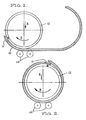
- Figure 1 shows the positioning of a recessed flat plate 10 onto the gripper 11.
- the mandrel 12 is rotatably mounted on a horizontal axis.
- the mounting means for the mandrel is mounted for controlled up and down movement under the influence of preferably hydraulic power cylinders (not shown).
- the mandrel 12 Upon location of the plate adjacent to the gripper 11, the mandrel 12 is moved down in the direction of arrow A to engage the pressure rollers 14 and is rotated towards the plate edge to force the edge of the plate home into full engagement with the gripper means 11.
- the effect of moving mandrel 12 is to ensure surface to surface contact along the entire length of the plate with the mandrel as the plate edge is being forced into the gripper.
- stage 2 of the bending operation Similar procedure is followed in stage 2 of the bending operation when gripping the opposite edge of the plate prior to bending the uncurved half of the plate.
- the notching or recessing of the plate is necessary where its thickness to diameter ratio exceeds a maximum limit.
- the gripper 11 must be radially dimensioned within limits to enable acceptance of the plate edge because of the possibility of fouling with the curved plate during the final stages of curving.
- a recess is machined in the edges of the plate so that the gripper can be accommodated within the total plate thickness relative to the recessed plate edge and enables curving of thick plates on relatively small diameter mandrels.
- the reduced thickness of the recessed plate edge enables curving of thick plates on relatively small diameter mandrels.
- the D/t ratio (where D is the pipe diameter and t plate thickness) to improve from approximately 30 to about 25 on structural grade steels and from about 20 to about 16 on high strength steels.
Landscapes
- Engineering & Computer Science (AREA)
- Mechanical Engineering (AREA)
- Bending Of Plates, Rods, And Pipes (AREA)
- Rigid Containers With Two Or More Constituent Elements (AREA)
- Metal Rolling (AREA)
Claims (2)
Priority Applications (1)
| Application Number | Priority Date | Filing Date | Title |
|---|---|---|---|
| AT81304316T ATE11114T1 (de) | 1980-09-19 | 1981-09-21 | Verfahren zum rundbiegen von blechen. |
Applications Claiming Priority (2)
| Application Number | Priority Date | Filing Date | Title |
|---|---|---|---|
| AUPE565880 | 1980-09-19 | ||
| AU5658/80 | 1980-09-19 |
Publications (2)
| Publication Number | Publication Date |
|---|---|
| EP0049079A1 EP0049079A1 (de) | 1982-04-07 |
| EP0049079B1 true EP0049079B1 (de) | 1985-01-09 |
Family
ID=3768712
Family Applications (1)
| Application Number | Title | Priority Date | Filing Date |
|---|---|---|---|
| EP81304316A Expired EP0049079B1 (de) | 1980-09-19 | 1981-09-21 | Verfahren zum Rundbiegen von Blechen |
Country Status (7)
| Country | Link |
|---|---|
| US (1) | US4428215A (de) |
| EP (1) | EP0049079B1 (de) |
| JP (1) | JPS5781924A (de) |
| KR (1) | KR870001074B1 (de) |
| AT (1) | ATE11114T1 (de) |
| CA (1) | CA1174574A (de) |
| DE (1) | DE3168168D1 (de) |
Families Citing this family (10)
| Publication number | Priority date | Publication date | Assignee | Title |
|---|---|---|---|---|
| US4606208A (en) * | 1984-05-16 | 1986-08-19 | Kaiser Steel Corporation | Pipe forming apparatus |
| US4911209A (en) * | 1989-03-15 | 1990-03-27 | Expo Wire Company | Method and apparatus for forming wire mesh cages |
| JPH0460314U (de) * | 1990-10-01 | 1992-05-25 | ||
| FR2673863B1 (fr) * | 1991-03-14 | 1995-05-19 | Snecma | Procede et outillage de fabrication d'une piece annulaire en tole. |
| CN1053404C (zh) * | 1993-04-05 | 2000-06-14 | 肯尼斯·M·休姆 | 管子成形机及方法 |
| DE50012312D1 (de) * | 1999-03-05 | 2006-04-27 | Elpatronic Ag Bergdietikon | Verfahren zum rundbiegen eines blechs und mehrwalzen-vorrichtung zur durchführung des verfahrens |
| US6167737B1 (en) * | 2000-04-17 | 2001-01-02 | Duro Dyne Corporation | Vane forming apparatus |
| CN103212656B (zh) * | 2012-01-18 | 2014-11-26 | 番禺珠江钢管有限公司 | 管端保护器轧机 |
| JP6020515B2 (ja) * | 2014-05-30 | 2016-11-02 | トヨタ自動車株式会社 | サブマフラ外筒の製造方法及び製造装置 |
| CN111318596A (zh) * | 2020-03-25 | 2020-06-23 | 江门市腾宏金属制品有限公司 | 一种不锈钢管制管机 |
Family Cites Families (14)
| Publication number | Priority date | Publication date | Assignee | Title |
|---|---|---|---|---|
| US172606A (en) | 1876-01-25 | Improvement in the manufacture of tubes for lining ordnancf | ||
| DE618901C (de) * | 1933-12-23 | 1935-09-20 | Wilhelm Heinen | Vorrichtung zum Biegen von Blechstreifen o. dgl., insbesondere zu mehr oder weniger g eschlossenen Roehren |
| US2265187A (en) * | 1939-12-16 | 1941-12-09 | American Can Co | Can bodymaker |
| DE906443C (de) * | 1944-10-29 | 1954-03-15 | Eisenwerk Rothe Erde G M B H | Hilfsvorrichtung zum Vorbiegen der Randstreifen von mittels einer Dreiwalzenbiegemaschine, insbesondere in Ringform zu biegenden Flachstahltafeln |
| US2706328A (en) | 1950-11-21 | 1955-04-19 | Karmazin John | Method and blank for making tubing |
| US2730135A (en) | 1951-09-10 | 1956-01-10 | Bundy Tubing Co | Tubing or method of making tubing |
| FR1265630A (fr) | 1960-08-19 | 1961-06-30 | Schmidt Gmbh Karl | Procédé pour la fabrication de flotteurs sphériques pour filets de pêche |
| JPS4816417B1 (de) * | 1968-02-15 | 1973-05-22 | ||
| FR2097182A7 (en) * | 1970-07-04 | 1972-03-03 | Ferranti Albino | Sheet metal cylinders - bending of long lengths |
| FR2100162A5 (de) * | 1970-07-04 | 1972-03-17 | Ferranti Albino | |
| US3879994A (en) | 1973-08-16 | 1975-04-29 | Kenneth Michael Hume | Plate rolling |
| JPS5051061A (de) * | 1973-08-29 | 1975-05-07 | ||
| DE2620768A1 (de) | 1976-05-11 | 1977-11-24 | Otto Bihler | Verfahren und vorrichtung zum biegen von runden teilen aus draht- oder bandmaterial |
| EP0029345B1 (de) * | 1979-11-15 | 1984-05-02 | Kenneth Michael Hume | Verfahren und Apparat zum Walzen von Blech zum Herstellen eines im wesentlichen zylindrischen Gegenstandes |
-
1981
- 1981-09-18 CA CA000386177A patent/CA1174574A/en not_active Expired
- 1981-09-18 JP JP56147691A patent/JPS5781924A/ja active Pending
- 1981-09-18 KR KR8103482A patent/KR870001074B1/ko not_active Expired
- 1981-09-18 US US06/303,515 patent/US4428215A/en not_active Expired - Lifetime
- 1981-09-21 EP EP81304316A patent/EP0049079B1/de not_active Expired
- 1981-09-21 AT AT81304316T patent/ATE11114T1/de not_active IP Right Cessation
- 1981-09-21 DE DE8181304316T patent/DE3168168D1/de not_active Expired
Also Published As
| Publication number | Publication date |
|---|---|
| KR870001074B1 (en) | 1987-06-04 |
| CA1174574A (en) | 1984-09-18 |
| ATE11114T1 (de) | 1985-01-15 |
| KR830007161A (ko) | 1983-10-14 |
| EP0049079A1 (de) | 1982-04-07 |
| JPS5781924A (en) | 1982-05-22 |
| US4428215A (en) | 1984-01-31 |
| DE3168168D1 (en) | 1985-02-21 |
Similar Documents
| Publication | Publication Date | Title |
|---|---|---|
| EP0049079B1 (de) | Verfahren zum Rundbiegen von Blechen | |
| US5018379A (en) | Apparatus and method for crimping end of can body | |
| JP2004508205A (ja) | パイプ製作装置 | |
| WO1992011976A1 (en) | A method for pulling bearings, a bearing puller and use thereof | |
| CA1172878A (en) | Method and tool for the cold forging of internally profiled tubes | |
| US2737707A (en) | Method and apparatus for forming flanged bearings | |
| US3879994A (en) | Plate rolling | |
| GB1334564A (en) | Method and apparatus for making wheel rims | |
| CN203875140U (zh) | 一种钢卷开卷机变径涨头装置 | |
| EP0029345B1 (de) | Verfahren und Apparat zum Walzen von Blech zum Herstellen eines im wesentlichen zylindrischen Gegenstandes | |
| JPS5877719A (ja) | 管端部フランジ成形法及びその成形機 | |
| EP1091817B1 (de) | Ringförmiger werkzeughalter sowie maschine zum herstellen von nägeln mit einem solchen werkzeughalter | |
| JP2010069484A (ja) | 平板のロール曲げ方法及び平板のロール曲げ装置 | |
| US3587272A (en) | Internally knurled body and method and apparatus for forming same | |
| CN112045007A (zh) | 螺旋管的弯制方法 | |
| JPS587375B2 (ja) | 線材又は帯材からリングを曲成する方法及び装置 | |
| CN217700910U (zh) | 一种精准定位的冲弧机 | |
| CN102189149A (zh) | 一种高强度厚壁钢管的成形工艺方法 | |
| JPH08267152A (ja) | 金属管の曲げ加工方法及びその装置 | |
| EP0035245A1 (de) | Verfahren und/oder Vorrichtung zum Flanschen von Rohrenden | |
| WO1995002474A1 (en) | Tapered mandrels for plate bending | |
| US4112727A (en) | Method and apparatus for making pipe flanges | |
| CN112338057B (zh) | 一种法兰生产设备 | |
| CN112045006B (zh) | 反旋螺旋管的弯制方法 | |
| CN210761952U (zh) | 一种有色金属薄壁筒形锻件轧制过程转运专用工具 |
Legal Events
| Date | Code | Title | Description |
|---|---|---|---|
| PUAI | Public reference made under article 153(3) epc to a published international application that has entered the european phase |
Free format text: ORIGINAL CODE: 0009012 |
|
| AK | Designated contracting states |
Designated state(s): AT BE CH DE FR GB IT LU NL SE |
|
| 17P | Request for examination filed |
Effective date: 19820702 |
|
| ITF | It: translation for a ep patent filed | ||
| GRAA | (expected) grant |
Free format text: ORIGINAL CODE: 0009210 |
|
| AK | Designated contracting states |
Designated state(s): AT BE CH DE FR GB IT LI LU NL SE |
|
| REF | Corresponds to: |
Ref document number: 11114 Country of ref document: AT Date of ref document: 19850115 Kind code of ref document: T |
|
| REF | Corresponds to: |
Ref document number: 3168168 Country of ref document: DE Date of ref document: 19850221 |
|
| ET | Fr: translation filed | ||
| PG25 | Lapsed in a contracting state [announced via postgrant information from national office to epo] |
Ref country code: LU Free format text: LAPSE BECAUSE OF NON-PAYMENT OF DUE FEES Effective date: 19850930 |
|
| PLBE | No opposition filed within time limit |
Free format text: ORIGINAL CODE: 0009261 |
|
| STAA | Information on the status of an ep patent application or granted ep patent |
Free format text: STATUS: NO OPPOSITION FILED WITHIN TIME LIMIT |
|
| 26N | No opposition filed | ||
| PGFP | Annual fee paid to national office [announced via postgrant information from national office to epo] |
Ref country code: AT Payment date: 19860915 Year of fee payment: 6 |
|
| PGFP | Annual fee paid to national office [announced via postgrant information from national office to epo] |
Ref country code: NL Payment date: 19870930 Year of fee payment: 7 |
|
| PG25 | Lapsed in a contracting state [announced via postgrant information from national office to epo] |
Ref country code: AT Effective date: 19880921 |
|
| PG25 | Lapsed in a contracting state [announced via postgrant information from national office to epo] |
Ref country code: SE Effective date: 19880922 |
|
| PG25 | Lapsed in a contracting state [announced via postgrant information from national office to epo] |
Ref country code: LI Effective date: 19880930 Ref country code: CH Effective date: 19880930 Ref country code: BE Effective date: 19880930 |
|
| PGFP | Annual fee paid to national office [announced via postgrant information from national office to epo] |
Ref country code: GB Payment date: 19890228 Year of fee payment: 8 |
|
| BERE | Be: lapsed |
Owner name: HUME KENNETH MICHAEL Effective date: 19880930 |
|
| PG25 | Lapsed in a contracting state [announced via postgrant information from national office to epo] |
Ref country code: NL Effective date: 19890401 |
|
| NLV4 | Nl: lapsed or anulled due to non-payment of the annual fee | ||
| PG25 | Lapsed in a contracting state [announced via postgrant information from national office to epo] |
Ref country code: FR Free format text: LAPSE BECAUSE OF NON-PAYMENT OF DUE FEES Effective date: 19890531 |
|
| REG | Reference to a national code |
Ref country code: CH Ref legal event code: PL |
|
| PG25 | Lapsed in a contracting state [announced via postgrant information from national office to epo] |
Ref country code: DE Effective date: 19890601 |
|
| REG | Reference to a national code |
Ref country code: FR Ref legal event code: ST |
|
| PG25 | Lapsed in a contracting state [announced via postgrant information from national office to epo] |
Ref country code: GB Effective date: 19890921 |
|
| GBPC | Gb: european patent ceased through non-payment of renewal fee | ||
| EUG | Se: european patent has lapsed |
Ref document number: 81304316.3 Effective date: 19890614 |