EP0048645A1 - Elektrisch beheizter Ofen mit geringer thermischer Trägheit - Google Patents
Elektrisch beheizter Ofen mit geringer thermischer Trägheit Download PDFInfo
- Publication number
- EP0048645A1 EP0048645A1 EP19810401335 EP81401335A EP0048645A1 EP 0048645 A1 EP0048645 A1 EP 0048645A1 EP 19810401335 EP19810401335 EP 19810401335 EP 81401335 A EP81401335 A EP 81401335A EP 0048645 A1 EP0048645 A1 EP 0048645A1
- Authority
- EP
- European Patent Office
- Prior art keywords
- oven
- plates
- plate
- heat
- oven according
- Prior art date
- Legal status (The legal status is an assumption and is not a legal conclusion. Google has not performed a legal analysis and makes no representation as to the accuracy of the status listed.)
- Granted
Links
- 238000005485 electric heating Methods 0.000 title description 3
- 239000011810 insulating material Substances 0.000 claims abstract description 6
- 230000000284 resting effect Effects 0.000 claims abstract description 4
- 239000011449 brick Substances 0.000 claims description 56
- 239000011464 hollow brick Substances 0.000 claims description 23
- 239000000835 fiber Substances 0.000 claims description 11
- 238000010438 heat treatment Methods 0.000 claims description 8
- 244000144992 flock Species 0.000 claims description 5
- 239000011819 refractory material Substances 0.000 claims description 5
- 125000006850 spacer group Chemical group 0.000 claims description 4
- 230000000717 retained effect Effects 0.000 abstract 1
- 238000009413 insulation Methods 0.000 description 5
- 238000004519 manufacturing process Methods 0.000 description 5
- 238000010411 cooking Methods 0.000 description 4
- 238000010304 firing Methods 0.000 description 4
- 239000000463 material Substances 0.000 description 4
- 239000000919 ceramic Substances 0.000 description 3
- 238000001816 cooling Methods 0.000 description 3
- 238000012423 maintenance Methods 0.000 description 3
- 238000009434 installation Methods 0.000 description 2
- 239000002184 metal Substances 0.000 description 2
- 230000001133 acceleration Effects 0.000 description 1
- 238000005273 aeration Methods 0.000 description 1
- 230000000295 complement effect Effects 0.000 description 1
- 238000007599 discharging Methods 0.000 description 1
- 239000012212 insulator Substances 0.000 description 1
- 238000000034 method Methods 0.000 description 1
- 238000012986 modification Methods 0.000 description 1
- 230000004048 modification Effects 0.000 description 1
- 239000004576 sand Substances 0.000 description 1
- 238000007789 sealing Methods 0.000 description 1
- 238000009423 ventilation Methods 0.000 description 1
Images


Classifications
-
- H—ELECTRICITY
- H05—ELECTRIC TECHNIQUES NOT OTHERWISE PROVIDED FOR
- H05B—ELECTRIC HEATING; ELECTRIC LIGHT SOURCES NOT OTHERWISE PROVIDED FOR; CIRCUIT ARRANGEMENTS FOR ELECTRIC LIGHT SOURCES, IN GENERAL
- H05B3/00—Ohmic-resistance heating
- H05B3/62—Heating elements specially adapted for furnaces
- H05B3/66—Supports or mountings for heaters on or in the wall or roof
-
- F—MECHANICAL ENGINEERING; LIGHTING; HEATING; WEAPONS; BLASTING
- F27—FURNACES; KILNS; OVENS; RETORTS
- F27D—DETAILS OR ACCESSORIES OF FURNACES, KILNS, OVENS, OR RETORTS, IN SO FAR AS THEY ARE OF KINDS OCCURRING IN MORE THAN ONE KIND OF FURNACE
- F27D1/00—Casings; Linings; Walls; Roofs
- F27D1/04—Casings; Linings; Walls; Roofs characterised by the form, e.g. shape of the bricks or blocks used
- F27D1/06—Composite bricks or blocks, e.g. panels, modules
- F27D1/063—Individual composite bricks or blocks
- F27D1/066—Individual composite bricks or blocks made from hollow bricks filled up with another material
-
- F—MECHANICAL ENGINEERING; LIGHTING; HEATING; WEAPONS; BLASTING
- F27—FURNACES; KILNS; OVENS; RETORTS
- F27D—DETAILS OR ACCESSORIES OF FURNACES, KILNS, OVENS, OR RETORTS, IN SO FAR AS THEY ARE OF KINDS OCCURRING IN MORE THAN ONE KIND OF FURNACE
- F27D11/00—Arrangement of elements for electric heating in or on furnaces
- F27D11/02—Ohmic resistance heating
Definitions
- the present invention relates to the production of an oven heated by electrical resistance having a low thermal inertia.
- the reduction of the thermal inertia of an oven is particularly advantageous when it is an intermittent heating oven, so as to achieve, on the one hand, an energy saving insofar as one can maintain a quality of insulation similar to that of ovens of known types and, on the other hand, an acceleration of the operating cycles.
- the energy saving obviously comes from the fact that the calories stored by the insulating materials that the oven contains, calories which are lost at least partially at each operating cycle, are all the more reduced as the thermal inertia of the oven is weaker.
- the heat-insulating wall of an electrically heated oven consists of a stack of refractory bricks, which have sufficient mechanical strength to support the supports of the electrical resistances of the heating.
- refractory bricks have a high thermal inertia and store a large amount of heat at the time of the rise in temperature of the oven so that, for intermittent ovens where we carry out successive loading and unloading of parts to be cooked , there is a fairly high heat loss which results in an unfavorable thermal efficiency; in addition, the duration of the cooking cycle is greater the greater the thermal inertia of the oven, so that ovens of this type unfortunately have a reduced operating rate.
- Refractory heat-insulating materials which, on the one hand, have low thermal inertia and, on the other hand, constitute good thermal insulators.
- these materials made from refractory fibers, always have a low mechanical resistance, so that, if they are used in place of refractory bricks for a conventional production of the heat-insulating walls of an oven, it is no longer possible. to hang the electric heating elements of the oven on the walls, especially if the temperatures reached in the oven are high, for example of the order of 1200 ° C., as for ceramic firing ovens.
- the object of the present invention is to describe an electrically heated oven, the heat-insulating wall of which is produced by means of a material with low thermal inertia and good insulation characteristics, the invention having provided special means allowing the support of electrical heating resistances despite the low mechanical resistance of the insulating materials used.
- the present invention therefore has for its object an oven heated by electrical resistances comprising a heat-insulating wall held by a frame, supports of electrical resistances being arranged on the face of said wall which is turned towards the interior of the oven, characterized by the fact that the heat-insulating wall consists of an assembly of modular elements made of a thermally insulating material with low mechanical resistance and low thermal inertia, the resistance supports being arranged at the level of the horizontal joint planes of the assembled modular elements and consisting of rigid refractory plates assembled side by side horizontally, each plate being supported by at least one rigid support member disposed inside a modular element of the wall, said member resting on the plate, which is located at right him at a lower level, the pads, which are at the lowest level being supported by an o carrier, which rests on the frame of the oven.
- the modu elements laires are hollow bricks made of a felt of refractory fibers; the hollow bricks are filled, preferably after their placement, with a flock of loose refractory fibers; the heat-insulating wall is made up of a single thickness of modular elements, each modular element being fixed to the frame of the oven by at least one clip disposed on the face of the modular element, which faces the outside of the oven; the fasteners of the modular elements are arranged at the horizontal joint planes of said elements; in the middle zone of each element, each fastener acting simultaneously on two superimposed modular elements.
- the plates constituting the resistance supports have a substantially rectangular shape and have two flanges substantially parallel to a plate edge, these two flanges being arranged inside the oven and delimiting between them a channel, where an electrical resistance is placed. heating, part of the wafer being arranged inside the heat-insulating wall;
- the plates constituting a resistance support in a horizontal plane are arranged with contiguous edges and constitute a continuous channel on the internal face of the heat-insulating wall, the joints of two adjacent plates being offset with respect to the joints of two adjacent modular elements of a same level of the wall;
- the joint of two adjacent plates of a resistance support is substantially perpendicular to the heat-insulating wall of the furnace and disposed in the central zone of a modular element, the length of the plates being equal to the length of the modular elements of the wall;
- each plate has a third flange, which is arranged in the vicinity of the middle of the thickness of the heat-insulating wall, parallel to the other two flanges and along an edge of the plate; the third
- the rigid support members are tubes of refractory material, each tube being positioned with respect to each of the plates, between which it forms me a spacer, by a centering span; each plate has in relief, in its part located inside the heat-insulating wall and on either side of its horizontally arranged mean plane, at least one boss whose horizontal section corresponds, at least in part, to the section inner right of the tubes constituting the load-bearing members; the tubes constituting the carrying members have a circular section and each plate comprises, on either side of its horizontally arranged mean plane, a boss having a horizontal section in a semicircle, formed at the edge of the plate to constitute with the boss corresponding to the adjacent plate a circular boss having substantially the diameter of the inner section of the tubes; the face of each hollow brick, which is arranged towards the inside of the oven, is inserted between the tube placed inside said brick and that of the edges delimiting the channel which is the most towards the outside of the oven.
- the structure defined above made it possible to use materials with low thermal inertia despite their low mechanical resistance and nevertheless to ensure satisfactory maintenance of the electrical resistance supports. It has also been found that the structure defined above makes it possible to considerably improve the thermal efficiency of electrically heated ovens and more particularly of intermittent ovens.
- the invention finds, in particular, its application in furnaces for firing ceramic pieces, where it has been noted, thanks to the invention, an energy saving of 30% for an oven performing a firing at about 1200 ° C with an available interior volume of 8m 3 and cooking a load of 1200 kg.
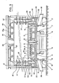
- the oven according to the invention comprises an external frame designated by 1 as a whole; the frame 1 consists of an assembly of metal beams 2 between which are placed sheets 3 constituting the external covering of the furnace.
- the frame 1- has the general shape of a very long rectangular parallelepiped; the oven constitutes a tunnel comprising a bottom 4 and an entry door 5 capable of being opened for charging and discharging the load whose oven is intended for cooking.
- the oven which will be described by way of example, is intended for firing a ceramic load of 1200 kg at 1230 ° C. Its useful internal volume is 3 of 8m 3 .
- the theoretical heating power is 340 Kva.
- the load is introduced into the tunnel, which the oven constitutes, on three wagons, which roll on rails 6 arranged on the ground, on either side of the axis of the oven and parallel to this axis.
- the wagons, designated by 7 as a whole, are clearly visible in Figures 5 and 6 of the drawing; Figure 6 shows only, due to the removal of the middle part of the section, the ends of the first and third wagons introduced into the oven.
- the wagons 7 have a refractory plate 8, which supports an insulating layer 9 on which are placed, in refractory angles 10, electrical resistances 11.
- the plate 8 supports vertical tubes 12, which pass through the heat-insulating layer 9 and support tables 13 on which is placed the load to be cooked.
- the tubes 12 and the tables 13 are made of refractory material.
- the insulating layer 9 is produced by means of an assembly of hollow bricks made of a felt of refractory fibers; in this example, bricks having the trade name "FIBERCHROM” produced by the American Company "Johns-Manville” were used. These bricks have a substantially parallelepiped shape and have on one of their small lateral faces a rounded relief 14a, which cooperates for assembly with a rounded hollow 14b of corresponding shape.
- the insulating layer 9 is produced by assembling a single thickness of these bricks on the plate 8, the two longitudinal edges of the layer 9 having rounded reliefs 14a, the front transverse edge of the layer 9 also having a rounded relief 14a, while the rear transverse border represents a rounded hollow 14b.
- hollow bricks 15 identical to the bricks constituting the layer 9, oriented so that facing rounded reliefs 14a , the hollow bricks 15 have a rounded hollow 14b and that opposite a rounded hollow 14b, the hollow bricks 15 have a rounded relief 14a.
- a clearance 16 has been provided for ensuring the placement of the wagons 7 in the furnace, the thermal sealing of the oven vis-à-vis the outside being produced by metal plates 17 arranged vertically along the longitudinal edges of the wagons, said plates 17 plunging into angles 18 filled with sand 19 and arranged at the base of the longitudinal walls of the oven .
- the bricks 15 are held on the frame or on the door structure by fasteners 22 each consisting of a bolt and a retaining plate, the retaining plate being placed in the hollow brick 15; it should be noted that the fasteners 22 are thermally protected by the bricks 15 and therefore do not have to suffer from the rise in temperature inside the oven.
- the bricks 15 are filled, at the time of their installation, with a flock of loose refractory fibers in order to improve the insulation.
- the heat-insulating wall of the oven is thus produced, for its lower horizontal layer, by the insulating layer 9 and the bricks 15.
- the upper horizontal part of the heat-insulating wall it is produced in the same way by an assembly of bricks hollow 23, which are supported by fasteners 24 by the beams 2, which form the roof of the oven.
- the fasteners 24 are made up of bolts and fastening plates and are protected from the rise in temperature by the insulating layer that constitutes the bricks 23 themselves.
- the bricks 23 have on their edges recesses 23a, 23b allowing their mechanical assembly to constitute the vault of the oven.
- an air exhaust orifice 25 is provided, which is connected to a suction fan, to ensure rapid cooling of the oven; during the cooling phase, aeration hatches 26 open at the bottom of the oven are opened so as to allow cold air to enter and the oven to cool.
- the side wall of the oven carries electrical resistances intended to ensure the heating of the oven.
- the resistors 11 previously described have an action complementary to that of the resistors 27.
- the problem solved by the invention is the production of a lateral heat-insulating wall by means of hollow bricks of the same type, as those which constitute the layer insulating 9, simultaneously ensuring the support of resistors 27; the difficulty comes the fact that the hollow bricks "FIBERCHROM", if they have a low thermal inertia, also have a low mechanical resistance so that they are not capable of carrying the weight of the supports of the resistors 27.
- the bricks The hollow tubes 15 are traversed by tubes 28 of resistant refractory material, these tubes 28 resting by their base on the supports 20 and coming, by their high end, at the level of the first resistance support.
- the tube 28 passes through a hollow brick 29, the front part of which is hollowed out to allow the passage of the tube 28.
- the part of the tube 28, which projects above the corresponding brick 15, is surrounded by a sleeve 30 ensuring its thermal protection, said sleeve 30 stopping at the same level as the tube 28.
- the sleeve 30 can be obtained by cutting a hollow brick identical to brick 29.
- the plate 31 is arranged, which constitutes the resistance support 27 having the lowest level on the side wall of the oven.
- a resistance support is arranged horizontally on the side wall of the oven and is constituted by the assembly of plates 31 arranged side by side.
- the plates 31 are made of a refractory material having good mechanical strength and have a shape which, seen in plan, is substantially rectangular.
- the flanges 32 and 33 are formed along the two longitudinal edges of each plate 31 , which project from one side of the mean plane of the plate.
- a rim 34 which projects on either side of the mean plane of the wafer.
- the flanges 32 and 34 define between them a channel 35 inside which the heating resistor 27 can be positioned.
- the plate 31 comprises, on its transverse border and on the and on the other side of its mean plane, a boss 36 having, seen in plan, the shape of a semicircle.
- the channel 35 is continuous and the bosses 36 of two adjacent plates constitute circular bosses.
- the tube 28 is arranged below a boss 36 and supports two adjacent plates 31, in the plate zone which is located beyond the rim 34 in the direction of the boss 36.
- the tube 28 is located in the middle zone of the bricks 29 and 30 so that the joints of these bricks are offset relative to the seals of the plates 31; the length of the bricks 29 and 30 is the same as the length of the plates 31.
- each brick is placed in line with the row of bricks, which is lower than it; it has on its underside a cutout 38, which allows the passage of the rim 33 of the underlying plate 31; it has, on its upper face, a cutout 39 which allows the embedding of the plate 31 disposed above the brick 37, which plate 31 rests by means of a tube 40 on the underlying plate 31.
- the tube 40 is centered on a boss 36 of the underlying plate 31 and on a boss 36 of the plate 31 which it supports.
- the tube 40 is disposed inside the hollow brick 37 and its height is equal to the distance from two superimposed plates 31.
- the depth of the cutout 39 of the brick 37 is such that the plate 31 supported by the brick 37 is horizontal, the plate 31 coming from its lower face at the level of the upper edge of that of the faces of the brick 37, which is disposed towards the inside of the oven. It can therefore be seen that all of the superimposed plates 31 are carried, by means of the tubes 40 which act as spacers, by the tube 28 and, consequently, by the support 20 of the frame of the oven.
- the resistance supports do not have to be carried by the hollow bricks 37, which constitute the thermal insulation, so that it is no longer important that these bricks have their own mechanical resistance.
- the bricks 37 are also carried by the plates 31 arranged below them and there is therefore no risk of collapse of the stack of bricks 37 produced. to form the side wall of the oven.
- Each brick 37 is held against the chassis by fasteners 41 consisting of a fastening plate and a bolt, said fasteners being protected from the rise in temperature by the bricks 37 themselves.
- the bolt of the fasteners 41 is arranged at the level of the connection plane of the external faces of the bricks 37 and provision is made, for the passage of the bolts of the fasteners 41, a recess 42 in the corresponding wall of the brick 37.
- the fasteners 41 are disposed in the part of the bricks 37 which is located midway between the rounded reliefs 43a and the rounded recesses 43b, which allow the assembly of two bricks 37 arranged side by side in the same horizontal row; the conformations 43a, 43b are, of course, identical to the conformations 14a, 14b previously cited for the hollow bricks constituting the insulating layer 9.
- the attachment plate of an attachment 41 acts simultaneously on two superimposed bricks 37. Like the bricks of the insulating layer 9 and the bricks 15, the bricks 29, 30 and 37 are filled at the time of their installation with a flock of loose refractory fibers to improve the insulation.
- tubes 28 and possibly tubes 40 are also stuffed with refractory fibers in bulk.
- the faces of the bricks 37 which are located towards the inside of the furnace, are in fact inserted between the tubes 40 and the edges 34 of the plates 31. As a result, this is already ensured in the transverse direction of the plates 31 and of the heat-insulating wall formed by the set of bricks 37.
- the joints of two adjacent plates 31 of the same level are located approximately in the middle of the bricks 37, which support them and which overcome them.
- the cutouts 38 and 39 of the upper and lower planes of the bricks 37 make it possible, by cooperation with the rim 33 of the plates 31, to ensure the transverse maintenance of the plates with respect to the two rows of bricks, between which the plates are placed. square.
- the embodiment which has just been described, allows the weight of the resistance supports to be carried directly by the chassis thanks to the spacers 28 and 40 and also to support each brick of the heat-insulating wall so that bricks can be used whose mechanical resistance is very low.
- This technique therefore makes it possible to use bricks of low weight with low thermal inertia for the production of heat-insulating walls, which constitutes a great advantage in terms of energy saving, this advantage being all the more significant. that it is an intermittent oven.
- the time required for the cooling of the oven by ventilation is lower, since the thermal inertia of the oven is lower, and it is therefore possible to reduce the time of the cooking cycles and increase the production rates.
Landscapes
- Engineering & Computer Science (AREA)
- Mechanical Engineering (AREA)
- General Engineering & Computer Science (AREA)
- Furnace Details (AREA)
- Electric Stoves And Ranges (AREA)
Applications Claiming Priority (2)
| Application Number | Priority Date | Filing Date | Title |
|---|---|---|---|
| FR8020269A FR2490797A1 (fr) | 1980-09-19 | 1980-09-19 | Four a chauffage electrique ayant une faible inertie thermique |
| FR8020269 | 1980-09-19 |
Publications (2)
| Publication Number | Publication Date |
|---|---|
| EP0048645A1 true EP0048645A1 (de) | 1982-03-31 |
| EP0048645B1 EP0048645B1 (de) | 1984-04-04 |
Family
ID=9246124
Family Applications (1)
| Application Number | Title | Priority Date | Filing Date |
|---|---|---|---|
| EP19810401335 Expired EP0048645B1 (de) | 1980-09-19 | 1981-08-24 | Elektrisch beheizter Ofen mit geringer thermischer Trägheit |
Country Status (3)
| Country | Link |
|---|---|
| EP (1) | EP0048645B1 (de) |
| DE (1) | DE3162977D1 (de) |
| FR (1) | FR2490797A1 (de) |
Cited By (5)
| Publication number | Priority date | Publication date | Assignee | Title |
|---|---|---|---|---|
| WO1986004478A1 (en) * | 1985-01-25 | 1986-07-31 | Ludwig Riedhammer Gmbh | Electrically-heated industrial oven |
| FR2642512A1 (fr) * | 1989-02-02 | 1990-08-03 | Commissariat Energie Atomique | Four de frittage en continu |
| WO1996011371A1 (en) * | 1994-10-11 | 1996-04-18 | Bryan Groom Limited | Heat insulating arrangement |
| EP0758191A2 (de) * | 1995-08-09 | 1997-02-12 | Abb K.K. | Deglorofen |
| FR2818366A1 (fr) * | 2000-12-18 | 2002-06-21 | P A Technologies | Dispositif pour l'ancrage des revetements refractaires sur les parois des fours industriels, et fours equipes de tels dispositifs |
Citations (4)
| Publication number | Priority date | Publication date | Assignee | Title |
|---|---|---|---|---|
| US1794310A (en) * | 1929-07-31 | 1931-02-24 | Herbert J Mccauley | Electric furnace and electric resistance element therefor |
| US2688685A (en) * | 1951-10-29 | 1954-09-07 | Paul H Goodell | Sheath-resistance heater and panel supporting structures therefor which are built into heating devices |
| US4088825A (en) * | 1976-08-04 | 1978-05-09 | General Electric Company | Electric furnace wall construction |
| FR2394774A1 (fr) * | 1977-06-17 | 1979-01-12 | Produits Refractaires | Element de garnissage refractaire pour four ou analogue |
-
1980
- 1980-09-19 FR FR8020269A patent/FR2490797A1/fr active Granted
-
1981
- 1981-08-24 DE DE8181401335T patent/DE3162977D1/de not_active Expired
- 1981-08-24 EP EP19810401335 patent/EP0048645B1/de not_active Expired
Patent Citations (4)
| Publication number | Priority date | Publication date | Assignee | Title |
|---|---|---|---|---|
| US1794310A (en) * | 1929-07-31 | 1931-02-24 | Herbert J Mccauley | Electric furnace and electric resistance element therefor |
| US2688685A (en) * | 1951-10-29 | 1954-09-07 | Paul H Goodell | Sheath-resistance heater and panel supporting structures therefor which are built into heating devices |
| US4088825A (en) * | 1976-08-04 | 1978-05-09 | General Electric Company | Electric furnace wall construction |
| FR2394774A1 (fr) * | 1977-06-17 | 1979-01-12 | Produits Refractaires | Element de garnissage refractaire pour four ou analogue |
Cited By (7)
| Publication number | Priority date | Publication date | Assignee | Title |
|---|---|---|---|---|
| WO1986004478A1 (en) * | 1985-01-25 | 1986-07-31 | Ludwig Riedhammer Gmbh | Electrically-heated industrial oven |
| FR2642512A1 (fr) * | 1989-02-02 | 1990-08-03 | Commissariat Energie Atomique | Four de frittage en continu |
| EP0381587A1 (de) * | 1989-02-02 | 1990-08-08 | Commissariat A L'energie Atomique | Durchlaufsinterofen |
| WO1996011371A1 (en) * | 1994-10-11 | 1996-04-18 | Bryan Groom Limited | Heat insulating arrangement |
| EP0758191A2 (de) * | 1995-08-09 | 1997-02-12 | Abb K.K. | Deglorofen |
| EP0758191A3 (de) * | 1995-08-09 | 1997-05-28 | Abb Kk | Deglorofen |
| FR2818366A1 (fr) * | 2000-12-18 | 2002-06-21 | P A Technologies | Dispositif pour l'ancrage des revetements refractaires sur les parois des fours industriels, et fours equipes de tels dispositifs |
Also Published As
| Publication number | Publication date |
|---|---|
| FR2490797A1 (fr) | 1982-03-26 |
| DE3162977D1 (en) | 1984-05-10 |
| FR2490797B1 (de) | 1983-12-16 |
| EP0048645B1 (de) | 1984-04-04 |
Similar Documents
| Publication | Publication Date | Title |
|---|---|---|
| EP0048645B1 (de) | Elektrisch beheizter Ofen mit geringer thermischer Trägheit | |
| FR2544058A1 (fr) | Module(s) de garniture pour chariot de four | |
| EP2417072B1 (de) | Ofen und heizvorrichtung mit wärmesperre sowie heizverfahren mit diesem ofen | |
| FR2462671A1 (fr) | Capteur solaire, concu particulierement pour facades de batiments | |
| FR2908261A1 (fr) | "panneau chauffant etanche et unidirectionnel pour radiateur electrique et radiateur electrique incluant un tel panneau" | |
| FR2523148A1 (fr) | Batterie de fours a coke et procede pour la reparation de batteries anciennes | |
| EP0044787B1 (de) | Ofen mit austauschbaren Heizwänden zur Wärmebehandlung von Glasscheiben | |
| FR2549212A1 (fr) | Structures de support pour voutes de fours | |
| EP0490727B1 (de) | Vorrichtung und Tiegel zur Abscheidung aus der Gasphase | |
| EP0518746A1 (de) | Beschickungsanlage für das Tragen von Werkstücken in Ofen | |
| BE1004116A6 (fr) | Procede de carbonisation et installation pour la mise en oeuvre de ce procede. | |
| EP0148804B1 (de) | Balkenofen zur schnellen kontinuierlichen oder diskontinuierlichen Erwärmung von keramischen Produkten | |
| EP0565427B1 (de) | Vorrichtung zum Transportieren von Leiterplatten für eine Anlage zur thermischen Behandlung durch Konvektion und Installation zu seiner Verwendung | |
| BE1009250A3 (fr) | Procede et installation de chauffage de cuves, pour bain de metaux en fusion. | |
| FR2566817A1 (fr) | Element de construction constitue de deux blocs relies par une entretoise | |
| FR2752713A1 (fr) | Friteuse electrique a chauffage ameliore | |
| EP0286534B1 (de) | Bauteil für die Ofenauskleidung und Verfahren zu seiner Anbringung | |
| FR2705443A1 (fr) | Revêtement réfractaire modulable pour les parois d'une enceinte chauffante et notamment d'un four haute température et enceinte chauffante munie d'un tel revêtement. | |
| WO2004068044A1 (fr) | Dispositif de transfert thermique comprenant un module isolant | |
| FR2689330A1 (fr) | Caisson de protection thermique, notamment pour la protection contre le feu de câbles électriques. | |
| FR2649785A1 (fr) | Support pour materiel a cuire en ceramique | |
| FR2528153A1 (fr) | Four de cuisson pour produits alimentaires | |
| EP1111309A1 (de) | Gasofen | |
| BE857267A (fr) | Barriere coupe-feu | |
| FR3141160A1 (fr) | four verrier |
Legal Events
| Date | Code | Title | Description |
|---|---|---|---|
| PUAI | Public reference made under article 153(3) epc to a published international application that has entered the european phase |
Free format text: ORIGINAL CODE: 0009012 |
|
| 17P | Request for examination filed |
Effective date: 19810825 |
|
| AK | Designated contracting states |
Designated state(s): BE DE GB IT NL SE |
|
| ITF | It: translation for a ep patent filed |
Owner name: JACOBACCI & PERANI S.P.A. |
|
| GRAA | (expected) grant |
Free format text: ORIGINAL CODE: 0009210 |
|
| AK | Designated contracting states |
Designated state(s): BE DE GB IT NL SE |
|
| REF | Corresponds to: |
Ref document number: 3162977 Country of ref document: DE Date of ref document: 19840510 |
|
| PGFP | Annual fee paid to national office [announced via postgrant information from national office to epo] |
Ref country code: DE Payment date: 19840801 Year of fee payment: 4 |
|
| PGFP | Annual fee paid to national office [announced via postgrant information from national office to epo] |
Ref country code: NL Payment date: 19840831 Year of fee payment: 4 |
|
| PGFP | Annual fee paid to national office [announced via postgrant information from national office to epo] |
Ref country code: SE Payment date: 19840930 Year of fee payment: 4 Ref country code: BE Payment date: 19840930 Year of fee payment: 4 |
|
| PLBE | No opposition filed within time limit |
Free format text: ORIGINAL CODE: 0009261 |
|
| STAA | Information on the status of an ep patent application or granted ep patent |
Free format text: STATUS: NO OPPOSITION FILED WITHIN TIME LIMIT |
|
| 26N | No opposition filed | ||
| PG25 | Lapsed in a contracting state [announced via postgrant information from national office to epo] |
Ref country code: SE Effective date: 19850825 |
|
| PG25 | Lapsed in a contracting state [announced via postgrant information from national office to epo] |
Ref country code: NL Effective date: 19860301 |
|
| GBPC | Gb: european patent ceased through non-payment of renewal fee | ||
| NLV4 | Nl: lapsed or anulled due to non-payment of the annual fee | ||
| PG25 | Lapsed in a contracting state [announced via postgrant information from national office to epo] |
Ref country code: DE Effective date: 19860501 |
|
| BERE | Be: lapsed |
Owner name: ETS PORCHER Effective date: 19860831 |
|
| PG25 | Lapsed in a contracting state [announced via postgrant information from national office to epo] |
Ref country code: GB Effective date: 19881118 |
|
| PG25 | Lapsed in a contracting state [announced via postgrant information from national office to epo] |
Ref country code: BE Effective date: 19890831 |
|
| EUG | Se: european patent has lapsed |
Ref document number: 81401335.5 Effective date: 19860729 |