EP0048133B2 - Elektronische Handhabung von Glasgegenständen - Google Patents
Elektronische Handhabung von Glasgegenständen Download PDFInfo
- Publication number
- EP0048133B2 EP0048133B2 EP81304144A EP81304144A EP0048133B2 EP 0048133 B2 EP0048133 B2 EP 0048133B2 EP 81304144 A EP81304144 A EP 81304144A EP 81304144 A EP81304144 A EP 81304144A EP 0048133 B2 EP0048133 B2 EP 0048133B2
- Authority
- EP
- European Patent Office
- Prior art keywords
- output
- memory
- flop
- providing
- flip
- Prior art date
- Legal status (The legal status is an assumption and is not a legal conclusion. Google has not performed a legal analysis and makes no representation as to the accuracy of the status listed.)
- Expired
Links
- 230000015654 memory Effects 0.000 claims description 62
- 230000001360 synchronised effect Effects 0.000 claims description 14
- 230000006870 function Effects 0.000 claims description 9
- 238000004804 winding Methods 0.000 claims description 8
- 230000000977 initiatory effect Effects 0.000 claims description 5
- 230000004044 response Effects 0.000 claims description 5
- 210000003813 thumb Anatomy 0.000 claims description 5
- 125000004122 cyclic group Chemical group 0.000 claims description 4
- 238000012546 transfer Methods 0.000 claims description 4
- 230000001419 dependent effect Effects 0.000 claims 5
- 210000003811 finger Anatomy 0.000 description 13
- 230000008859 change Effects 0.000 description 9
- 238000010586 diagram Methods 0.000 description 8
- 230000005355 Hall effect Effects 0.000 description 6
- 230000009467 reduction Effects 0.000 description 6
- 238000004519 manufacturing process Methods 0.000 description 5
- 239000003990 capacitor Substances 0.000 description 4
- 238000012163 sequencing technique Methods 0.000 description 4
- 230000008901 benefit Effects 0.000 description 3
- 238000012937 correction Methods 0.000 description 3
- 230000008878 coupling Effects 0.000 description 3
- 238000010168 coupling process Methods 0.000 description 3
- 238000005859 coupling reaction Methods 0.000 description 3
- 230000001186 cumulative effect Effects 0.000 description 3
- 238000000034 method Methods 0.000 description 3
- 102100039215 Guanine nucleotide-binding protein G(t) subunit alpha-3 Human genes 0.000 description 2
- 101000888145 Homo sapiens Guanine nucleotide-binding protein G(t) subunit alpha-3 Proteins 0.000 description 2
- 238000001514 detection method Methods 0.000 description 2
- 239000011521 glass Substances 0.000 description 2
- WVULKSPCQVQLCU-BUXLTGKBSA-N glycodeoxycholic acid Chemical compound C([C@H]1CC2)[C@H](O)CC[C@]1(C)[C@@H]1[C@@H]2[C@@H]2CC[C@H]([C@@H](CCC(=O)NCC(O)=O)C)[C@@]2(C)[C@@H](O)C1 WVULKSPCQVQLCU-BUXLTGKBSA-N 0.000 description 2
- 230000007246 mechanism Effects 0.000 description 2
- 230000004048 modification Effects 0.000 description 2
- 238000012986 modification Methods 0.000 description 2
- 239000004065 semiconductor Substances 0.000 description 2
- 238000003860 storage Methods 0.000 description 2
- 208000000044 Amnesia Diseases 0.000 description 1
- 230000009471 action Effects 0.000 description 1
- 230000003213 activating effect Effects 0.000 description 1
- 230000004075 alteration Effects 0.000 description 1
- 230000015556 catabolic process Effects 0.000 description 1
- 238000013461 design Methods 0.000 description 1
- 238000009826 distribution Methods 0.000 description 1
- 238000005816 glass manufacturing process Methods 0.000 description 1
- 231100000863 loss of memory Toxicity 0.000 description 1
- 239000000463 material Substances 0.000 description 1
- 238000012544 monitoring process Methods 0.000 description 1
- 230000001960 triggered effect Effects 0.000 description 1
Images


Classifications
-
- C—CHEMISTRY; METALLURGY
- C03—GLASS; MINERAL OR SLAG WOOL
- C03B—MANUFACTURE, SHAPING, OR SUPPLEMENTARY PROCESSES
- C03B35/00—Transporting of glass products during their manufacture, e.g. hot glass lenses, prisms
- C03B35/04—Transporting of hot hollow or semi-hollow glass products
-
- C—CHEMISTRY; METALLURGY
- C03—GLASS; MINERAL OR SLAG WOOL
- C03B—MANUFACTURE, SHAPING, OR SUPPLEMENTARY PROCESSES
- C03B9/00—Blowing glass; Production of hollow glass articles
- C03B9/30—Details of blowing glass; Use of materials for the moulds
- C03B9/40—Gearing or controlling mechanisms specially adapted for glass-blowing machines
- C03B9/41—Electric or electronic systems
-
- B—PERFORMING OPERATIONS; TRANSPORTING
- B65—CONVEYING; PACKING; STORING; HANDLING THIN OR FILAMENTARY MATERIAL
- B65G—TRANSPORT OR STORAGE DEVICES, e.g. CONVEYORS FOR LOADING OR TIPPING, SHOP CONVEYOR SYSTEMS OR PNEUMATIC TUBE CONVEYORS
- B65G47/00—Article or material-handling devices associated with conveyors; Methods employing such devices
- B65G47/74—Feeding, transfer, or discharging devices of particular kinds or types
- B65G47/90—Devices for picking-up and depositing articles or materials
-
- C—CHEMISTRY; METALLURGY
- C03—GLASS; MINERAL OR SLAG WOOL
- C03B—MANUFACTURE, SHAPING, OR SUPPLEMENTARY PROCESSES
- C03B9/00—Blowing glass; Production of hollow glass articles
- C03B9/30—Details of blowing glass; Use of materials for the moulds
- C03B9/44—Means for discharging combined with glass-blowing machines, e.g. take-outs
- C03B9/453—Means for pushing newly formed glass articles onto a conveyor, e.g. sweep-out mechanisms; Dead-plate mechanisms
-
- G—PHYSICS
- G05—CONTROLLING; REGULATING
- G05D—SYSTEMS FOR CONTROLLING OR REGULATING NON-ELECTRIC VARIABLES
- G05D13/00—Control of linear speed; Control of angular speed; Control of acceleration or deceleration, e.g. of a prime mover
- G05D13/62—Control of linear speed; Control of angular speed; Control of acceleration or deceleration, e.g. of a prime mover characterised by the use of electric means, e.g. use of a tachometric dynamo, use of a transducer converting an electric value into a displacement
Definitions
- This invention relates to glassware delivery and conveying apparatus used in glassware manufacturing, and particularly to the operation of that component of the glassware delivery and conveying apparatus which transfers hot, newly formed glassware articles from the dead plate of the individual section conveying system (I.S. dead plate) to the moving I.S. conveyor leading to the lehr.
- I.S. dead plate the individual section conveying system
- Becker, US-A-4 203 752 shows an arrangement which eliminates the need for a centrally driven cam shaft. Instead, each pushout is provided with its own electric motor. The motors are controlled by closed or open loop circuitry so that they all have the same rotational speed, which is held constant during a swinging out operation. The position out rates of rotation of each pushout is determiend by a crank mechanism connecting each motor to its respective pushout support shaft.
- An object of this present invention is to provide an electrically operated and electronically controlled glassware conveyor delivery apparatus.
- a second object is to provide such an electrical glassware conveyor delivery apparatus whose operating characteristics are electronically adjustable.
- a further object is to provide such an electronically adjustable electrically operated glassware conveyor delivery apparatus whose accuracy of operation does not degrade with length of service, which does not use a mechanical cam and which eliminates cumulative mechanical errors, and which is readily interchangeable between sections of an I.S. conveyor system or between conveyor systems.
- a further object is to provide such an electrical glassware conveyor delivery apparatus which is capable of detection and correction for loss of synchronization of operation and which is capable of detection and correction to an initial or "home" dead plate position.
- An even further object is to provide such an electronically controlled glassware conveyor delivery apparatus pushout with greater than 0.1° of accuracy of rotational position.
- a camless electronic glassware conveyor delivery apparatus comprising:
- the electrically operated, electronically controlled camless glassware conveyor delivery apparatus may operate in response to sequential timing signals indicative of I.S. machine synchronous operation.
- a mechanically operated electrical signal generator may be incorporated to transform I.S. synchronous operation from a point on the I.S. machine into electrical information representing cyclic I.S. machine operation in angular degrees.
- An electronic control circuit may utilize this electrical information representing angular rotation to provide control signals to drive an electric motor operated GCDA.
- a transfer drive may be utilized for coupling the motor to the pushout cylinder support unit of the GCDA for pivoting a hydraulic operated cylinder and attachments (robot fingers).
- the electronic control circuit may include a read only memory (ROM) containing pushout support shaft rotational time-position instructions for GCDA operation.
- ROM read only memory
- Additional circuitry may interrogate actual cylinder support shaft position for loss of synchronization as well as loss of improper initial (home) position and correction thereof.
- Identical, individual, electrically operated and electronically controlled GCDA units may be ganged together for multisection machine operation.
- These individual electronic GCDA units each containing the structure recited above may receive synchronous angular information from a common signal generator connected to the multi- section I.S. machine feeder and each individual electronic GCDA have its operative cycle initiated by a sequence of operation instruction from a central operator console.
- a glassware conveyor deliver apparatus is a machine which has been used in the glass industry to remove a newly formed glass- ware object deposited upon a dead plate of an I.S. conveyor. The pushout moves the object to a moving conveyor passing from the bottle machine area to a lehr where the glass object is cured.
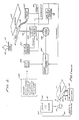
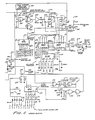
- Glassware manufacturing machine or (bottles) I.S. machines 101, Figure 1 are normally driven by electric motors, which electric motors are normally also connected to drive the glass- ware making materials feeder 103 to the I.S. machine 101.
- a feeder drive shaft 105 which is driven in synchronism with the cyclic operation of the I.S. machine 101 is normally (prior art) coupled through shaft and gear drive 106 to a cam operated pushout drive system 107.
- This cam driven system 107 operated to cause a hydraulic pushout cylinder 109 to pivot on a vertical support shaft 110.
- a mechanical arm or fingers 111 are positioned on the piston of the pushout cylinder 109 thereof forming a robot arm.
- the cam driven system 107 normally controls the hydraulic operation of the cylinder 109 via lines 121 causing its piston extension and retraction. Together, this operation extends the fingers 111 to engage a bottle or other glassware 113 on the depository or dead plate 115, part from the bottle machine 101, and moves it to an I.S. conveyor 117.
- the precise time-position operation of the cylinder 109, and the extension of the piston mounted fingers 111, as well as the rotation of the shaft 110 upon which the cylinder 109 rotates, are controlled solely by the shape, size and position of the cam on the shaft within drive 107.
- This cam determines the character of operation of the pushout regarding initiation and completion of robot finger 111 operation, as well as time-position operation, i.e. speed.
- the invention at hand is directed to an electrically driven and electronically controlled GCDA wherein the cylinder 109, Figure 2, as well as its piston mounted fingers 111, rotating support shaft 110 and hydraulic lines 121 are identical to the prior art teachings of Faure US ⁇ A ⁇ 3,595,365.
- the apparatus operates in the same environment with the same I.S. machine 101, I.S. conveyor 117, glassware 113 deposited upon the dead plate 115 of the I.S. conveyor system and feeder 103 drive 105.
- Electrical information, Figure 2 is received from a computer or other controller for individual section or multisection sequencing 201, and is synchronized to feeder 103 operation.
- This information 201 activates a start relay 203 which feeds a variable speed electronic motor controller circuit 205.
- This controller circuit 205 in turn drives a stepping motor 207.
- the stepping motor 207 is connected to drive the cylinder support shaft 110 through the coupling of the motor shaft via a combination forward drive clutch 209 and reverse drive clutch 211 structure.
- An end of half cycle rotation indicator 213 monitors the rotation of the support shaft 110 to engage the reverse direction clutch when the cylinder support shaft 110 has reached the end of its swing arc to cause the motor 207 to return the cylinder 109 to its initial or home position.
- the end of half cycle indictor also sends a retract signal 215 to the hydraulic valve controls 217 for the hydraulic lines 121.
- An end cycle or home position indicator 431 disengages 221 the reverse clutch 211 and the electronic motor control circuit 205 to wait for the mext operating cycle.
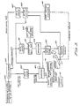
- the electrically driven and electronically controlled GCDA can also be implemented by an electronically controlled circuit utilizing a profile encoder 401 tied to a mechanical or electromechanical synchronization point (synchronizer) of an I.S. machine 403, Figure 3. It is understood that where speed reductions are needed for proper interfacing of this embodiment or others described herein, with a synchronization point of an I.S. machine, such reductions through gearing and other well known means are incorporated.
- the profile encoder 401 provides support shaft rotational time-position signals 124 representative of the synchronous operation of the I.S. machine in angular degrees. These signals 124 comprise a train of essentially electrical impulse signals which are shaped by a pulse shaper 405.
- the motor step pulses 128 from the first pulse shaper 405 are fed to a first amplifier 407 and to a down counter 409.
- the first amplifier 407 is connected to a commercially available motor drive card 135 for a commercially available digital stepping motor 133 connected to that drive card 135.
- An operator console 411 provides a pushout cylinder 109 retraction code 413 to the down counter 409.
- a retract signal 415 is sent from that down counter 409 to operate a hydraulic control 131 for retracting the cylinder fingers 111.
- a direction signal 417 is also generated by the profile encoder 401.
- This direction signal 417 is fed through a second pulse shaper 419 which feeds a flip-flop 421 which flip-flop 421 is connected to a second amplifier 423.
- This second amplifier 423 is also connected to the motor drive card 135 to cause the stepping motor 133 to rotate the pushout cylinder 109 via the support shaft 110 first in one direction during the first-half cycle of operation and then in the opposite direction during the second-half or return cycle.
- a left hand or right hand operation selector 425 sets the direction of flip-flop 421 to establish clockwise or counterclockwise first-half cycle rotation.
- the profile encoder also provides a reset signal 149 which is passed through a third pulse shaper 427 to a resynchronization flip-flop 429.
- This resynchronization flip-flop 429 receives signals from the stepping motor 133 and a zero position indicator 431.
- the zero position indicator is coupled to the support shaft 110 to detect its position relative to the "home" or zero or initial position.
- the output from the resynchronization flip-flop 429 feeds the first amplifier 407.
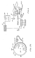
- the profile encoder 401 of Figure 3 can be implemented with a timing disc 433, Figure 3A, which is driven mechanically in synchronization with the I.S. machine 101 cyclic operation.
- This disk can have a series of timing slots 435 cut in its perimeter with a reset 438 being at the beginning of a direction slot 437.
- An arcuate slot 437, or the absence thereof 439, defines a second informational position on the disk 433 spaced inwardly from its perimeter, and dictates forward and reverse operation, respectively.
- a photo-electric system including a source 441 and detector 443 is used to generate the time position signals 125, direction signal 417 and reset signal 149 indicative of the rotation of the disk 433.
- An absence of slots provides a machine dwell time 445.
- the electrically driven and electronically controlled GCDA of the subject invention can more precisely be operated and have its operating perimeters easily changed when implemented with programmable control circuitry, Figure 4.
- the cylinder 109 as well as its piston mounted fingers 111, rotating support shaft 110 and hydraulic lines 121 are identical to the prior art teachings of Faure USPN 3,595,365.
- the apparatus is operated in the same environment as Figures 1 with the same I.S. machine 101, I.S. conveyor 117, glass-ware 113 deposited upon a dead plate 115 of the I.S. conveyor and feeder drive 105.
- each signal represents one, one-hundredth of a degree of angular rotation or other acceptable smaller or larger increments.
- Signals 125 produced by the generator 123 which may include pulses or impulses, are used by a controller 127.
- This controller 127 contains a read only memory chip(s) (ROMS) or in programmable memory form (PROMS) which is responsible for the position vs. time performance characteristic of the GDCA.
- An operator console 129 containing controls including switches, enables an operator to feed information, among it being specific piston retraction information and also dead plate 115 delay time, into the controller 127 which automatically modifies the point of cylinder 109 piston retraction with respect to support shaft 110 swing position and modifes reorientation of the signal generator 123, respectively, or other GCDA functions.
- Controller 127 output is fed to both hydraulic controls 131 for the hydraulic lines 121 to the cylinder 109 and to a stepping motor 133 through a typical motor drive card 135.
- the output shaft 137 of the stepping motor 133 is coupled to the support shaft 110 via a belt 139 drive or alternately by direct coupling.
- the belt 139 drive includes pulleys 141, 143 which provide a 4 to 1 speed reduction. However, other reduction values may be used.
- the motor 133 is controlled to rotate in one direction, change direction and return to the initial position in repeatable fixed increments of rotation which may be either of constant or variable repetition period and may also include variations in repetition period during each operational cycle for changes in velocity during various portions of the support shaft 110 rotation.
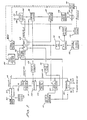
- the electrical and electronic features of Figure 4 can be seen in greater detail in Figure 5.
- the feeder-drive shaft 105 is connected directly to an encoder 147 which implements the signal generator or click 123 of Figure 4.
- the encoder 147 alternately can be tied to any mechanical or electrical synchronization point of the I.S. machine 101.
- This encoder 147 provides an initiating or reset signal 149 and a train of clock pulses 126 whose count provides feeder shaft 105 position and, therefore, I.S. machine angular information, respectively. In computer controlled or other types of systems these timing pulses are already available and the encoder 147 may not be needed.
- the clock pulses 126 are fed to a first counter 151, the angular position counter, and a part of the controller 127 of Figure 4.
- the output of this first counter 151 is connected to a comparator 153.
- the comparator 153 compares the first counter 151 output with information fed it from a rotational profile memory 155.
- This rotational profile memory 155 is a read only memory (ROM) or a programmable read only memory (PROM) which has been loaded or pre-programmed, respectively, with the rotational position vs. time information for the cylinder support shaft 110 providing identical operation characteristics to an ideal mechanical cam system.
- ROM read only memory
- PROM programmable read only memory
- any storage device whether analog or digital may provide substitute and equivalent functions of the (ROM) (PROM) 155.
- the rotational profile membory 155 is addressed by a second or address counter 157, which address counter 157 is in turn fed from the output of the comparator 153 via a pulse shaper 159.
- a second output from the second or address counter 157 is fed to an end cycle gate 161 whose output is in turn fed to a re-cynchronization flip-flop 163.
- the memory 155 contains a series of values representing support shaft 110 position in relation to feeder drive shaft 105 and, therefore I.S. machine position.
- the position counter 151, address counter 157, and comparator 153 operate in conjuction with the values programmed into the memory 155 to provide control signals to the stepping motor 133 and the hydraulic control 131.
- the pushout cylinder 109 is caused to rotate, as well as its apparatus, here robot fingers 111.
- Alternative circuitry may be used to control extension or retraction of the cylinder 109 according to the information contained in the program memory 155. While this program is used to control the operation of the GCDA to duplicate the operation of an ideal mechanical cam action GCDA, other programs may be substituted when pushout shaft 110 operation is to be altered. An electronic modification of pushpout rotation is thereby made possible. Such modification can be quickly and economically effected by a change in the stored program of the digital storage (PROM 155).
- a third output from the second or address counter 157 is fed to a direction flop-flop 165 via an end of half cycle rotation comparator (counter) 167 which monitors for support shaft swing (half circle operation at delivery).
- Direction flip-flop 165 provides either left-hand drive 168 or right-hand drive 170 directional information to the motor drive card 135 causing the motor 133 to rotate clockwise or counter-clockwise from its initial or "home" dead plate 1.
- the output from the pulse shaper 159 is also fed to a divide by 11 binary divider 169 whose output is in turn fed to a down counter 171.
- the initial count in the down counter 171 is established by thumb switches 172 which essentially constitute the operation console 129 of Figure 4.
- a "zero" counter output from the down counter 171 is used to operate a solenoid driver 173 which controls the hydraulic retraction 175 of the pushout cylinder 109.
- the combination of the solenoid driver 173 and retraction control value 175 constitute the hydraulic control element 131 of Figure 4.
- the thumb wheels 172 enable an operator to set the angular position of the cylinder 109 where its piston begins to retract.
- the resynchronization flip-flop 163 provides output information to the motor drive card 135 and to a summer/enable gate 181.
- This summer/ enable gate 181 receives pulses from the pulse shaper 159 and a zero position oscillator 177, which oscillator 177 is activated by a signal from the resynchronization flip-flop 163 and a motor winding comparator 179.
- the reset signal 149 from the encoder 147 is also connected to the resynchronization flip-flop 163.
- Motor drive card 135 is connected directly to the stepping motor 133.
- the shaft 137 of this motor 133 is connected to the cylinder support shaft 110 via the timing belt and pulley 4 to 1 reduction described in connection with Figure 4 above.
- Left and right-hand rotational direction signals 168,170 are, selectively, exclusively, each input to the motor drive card 135.
- a zero position sensing switch 450 tied to the cylinder support shaft 110 operates to provide yet another signal to the resynchronization flip-flop 163.
- the zero position sensing switch 450 can be a Hall-effect detector with associative magnet or, alternately, photo-electric, mechanical gate or other unique position indicating device. This zero position switch operates in conjunction with the motor winding comparator 179 to control the zero position oscillator 177.
- half-cycle comparator 167 is also connected to the re-synchronization flip-flop 163 via a half-cycle re-synchronization gate 186.
- This gate 186 also receives an input from a half-cycle position switch 184 which is mechanically tied to the pushout 109 to indicate the physical position of that mechanical apparatus and loss of synchronization at half-cycle operation.
- This circuit operates to provide clock pulses 126 which provides angular rotation of the feeder drive shaft 105 in increments of one one-hundredth of a degree of rotation.
- the counters 151 and 157 along with the comparator 153, rotation profile memory 155, end of half-cycle comparator 167, direction flip-flop 165, pulse shaper 159, end of cycle gate 161, re-synchronization flip-flop 163, binary divider 169, down counter 171, zero position switch 183, summer/ enable element 181, zero position oscillator 177 and motor winding comparator 179 comprise the programmable controller 127 of Figure 4.
- the stepping motor 133 is connected to provide digital rotational increments of .36 degrees. With the 4 to 1 timing belt reduction via the pulleys 141, 143, the pushout shaft 110 rotates the pushout cylinder 109 in .09 degree steps. These parameters can be changed by accepted techniques. When a loss of synchronization is detected at end of half cycle rotation or at the "zero" position, the oscillator 177 is engaged to drive the pushout support shaft 110 to half cycle position or home (zero initial position), respectively.
- a conveyor timing control 150 located on the operator console 129 alters encoder synchronisation to the I.S. machine 101 to change overall synchronization vie electromechanical apparatus.
- This circuit provides accuracy and dependability of cylinder 109 positon or angle or rotation with respect to time and carefully synchronizes pushout cylinder 109 as a function of the rotation of the feeder drive shaft 105.
- the circuit also provides the ability to correct out of synchronous operation at half-cycle and to reset to the correct initial position point within one cycle and without cumulative errors.
- This camless electronic GCDA circuit provides an advantage over prior art mechanical, cam operated GCDA's in that accuracy is maintained over the entire range of operating speeds, whereas with the mechanical cam apparatus the same is not true and performance can vary between identical units and provide cumulative errors.
- FIG. 6 shows the schematic circuitry for the electronic GCDA, including a signal generating encoder 147.
- This device 147 may be an electro-optical encoder such as can be commercially obtained from Baldwin Electronics Incorporated, and is employed to provide signal wave-forms indicative of feeder drive shaft 105 rotation.
- a zero reference position signal 148 is recieved from the encoder 147 to indicate an initial or indexing point for the GCDA operation.
- Clock pulses 126 are fed from the encoder 147 to a counter comprised of serially connected RCA type CD 4024 and DC 4040 counter chips 183, 185. These pulses 126 arrive at the counter 183, 185 by passing through a 1000 pf capacitor 187 and a two input NAND gate 189.
- Serially connected counters 183, 185 implement the position counter 151 of Figure 5.
- the comparator 153 comprises four serially connected RCA type CD 4063 comparator chips 191, 193, 195 and 197 while the rotational profile memory 155 is implemented by two Intel type 12716 programmable memory (PROMS) 199, 201, connected in series and to the comparators 191, 193, 195, 197.
- PROMS Intel type 12716 programmable memory
- An RCA type CD 4040 counter 203 is used as the address register 157 for addressing the PROMS 199, 201. Also connected to this address counter 203 is the end of half cycle rotation comparator or change or direction counter implemented with an RCA type CD 4068 NAND chip counter 205 and National Semiconductor Corporation type 556 timer 207 connected to operate as a "one shot" on the output of the counter 205.
- An output from the change of direction one shot 207 is connected through an inverter 209 to a pair of NAND gates 211, 213 which NAND gates 211, 213 operate as the direction flip-flop 165 of Figure 5.
- the output from the NAND gate 211 can be used to dictate left-hand operation, i.e. driving the stepping motor clockwise (clockwise, counter-clockwise direction being selectable), while the output from the other NAND gate 213 can be used for right-hand operation, i.e. driving the stepping motor 133 counter-clockwise.
- a switch 215 may select initial direction between the output of the NAND gates 211 and 213 for either left-hand or right-hand pushout operation.
- the output from the switch 215 is fed through an amplifier circuit including transistor 217.
- the output from transistor 217 is fed to the motor drive card 135.
- the circutiry of this drive card 135 is well known in the art and commercially available. It should be understood that the attendant circuit interconnections of the components discussed above in connection with Figure 6, as well as the components which will be discussed below, are made in accordance with manufactures' specifications with pin connections, resistors and capacitors chosen according to a manufacturer's user's manual or catalogue.
- the zero position signal 148 provides a reset pulse 149 through a 1000 p.fd. capacitor 229, a NAND gate 231 and an inverter 233 directly to the memory address counter 203 and to the left-hand NAND gate 211 of the direction flip-flop through another inverter 235.
- the reset pulse 149 in its inverter form, exits the NAND gate 231 and is fed to a reset flip-flop comprising the NAND gates 237 and 239 whose output is fed to the clock NAND gate 189 to the counter chip 183.
- the reset pulse 149 output from the inverter 233 is also connected to reset the counter chips 183 and 185.
- the output from the comparator chip 197 is fed to a pulse shaper comprising a National Semiconductor Corporation type 556 timer connected as a one-shot 241.
- the output from this one-shot 241 is connected to the NAND gate 221 and to the address counter 203.
- the output from the pulse shaper, one-shot 241 is also connected to transistor 219 via gates 221, 223, and diode 225.
- the transistor 219 provides motor step drive to motor drive card 135.
- An RCA type CD 4013 "D"-type flip-flop 245 is utilized as the resynchronization flip-flop 163 of Figure 5.
- This flip-flop 245 receives a reset pulse 149 from the inverter 233 and is connected to a NOR gate 243, this NOR gate operating as the summer and enable 181 component, Figure 5.
- the pushout cylinder 109 position detector 183 is implemented by a Hall-effect position indicator 247 and associated magnet which indicates when the pushout cylinder 109 is at its initial or zero- "home" position.
- This Hall-effect indicator 247 has an output which is connected to a three input NAND gate 249 and to a second three input NAND gate 251.
- a third three input NAND gate 253 is interconnected with the second three input NAND gate 251 to form a flip-flop with the first three input NAND gate 249 acting as an inverter input to the third NAND gate 253.
- the output from the paired NAND gates 251, 253 is inverted through a hex invertor 255 and then input into the resynchronization flip-flop 245.
- the three input NAND gates 249, 251, 253 and the invertor 255 act as the zero position switch 183 of Figure 5.
- the end of cycle gate 161 of Figure 5 is implemented by an 8 input NAND gate of the RCA type CD 4068, element 257, figure 6. This chip 257 is connected to the PROM chip 201.
- a hex invertor 259 connects the output from the end of cycle operation chip 257 to a two input NOR gate 261, which NOR gate 261 has its other input connected to the resynchronization flip-flop 245 and is in parallel to the "summer and enable" NOR gate 243.
- the output of the two input NOR gate 261 is connected to the gate 221 and is input to the "summer and enable” NOR gate 243.
- the "summer and enable” NOR gate 243 is connected to the motor drive card circuit 135 through a 47K Ohm resistor 263 and a type 2N2222A transistor 265.
- the resynchronization flip-flop 245 also drives the solenoid valve coil 175 via a Darlington type amplifier utilizing a 2N2222A transistor 267 and a 2N2219 transistor 269. These transistors 267, 269, as well as their attendant circuitry, implement the solenoid driver 173 of Figure 5.
- the motor winding comparator 179 of Figure 5 is implemented by an 8 input NAND gate of the RCA type CD 4068, element 271 and diodes 274, voltage divider 273 and transistor 275.
- This chip 271 receives inputs directly from the motor 133 windings.
- the output from the motor winding comparator chip 271 is input to an oscillator circuit.
- This oscillator circuit also receives an input from the resynchronization flip-flop in parallel to the inputs to the NOR gates 243, 261.
- This oscillator 177 of Figure 5 is of classical design, and the components thereof are available from such manufacturers as RCA, and comprise the NAND gates 273, 275, 277 and 279, as well as the attendant circuitry, including the variable resistor 281, the one meg Ohm resistance 283, the capacitors 285 and 287, and the diode 289 and 18K Ohm resistor 291.
- the output from the oscillator NAND gate 279 is input to transistor 219 via diode 277.
- a pair of serially connected 4 bit comparators of the RCA type CD 4063 elements 293, 295 are connected to the memory chip 201 to implement down counter 171 of Figure 5.
- the gates of chip 201 chosen for direct interconnection from the memory chip 201 provide a binary divide by 11 function.
- thumb wheel switches 172 are connected to the down counter chips 293, 295 through a BCD to binary converter 297.
- the thumb wheel switches 172 operate in binary-coded-decimal necessitating the utilization of a Texas Instruments Inc. type 74184 BCD to binary converter 297.
- the invention monitors electrical pulses provided by the electro-optical encoder 147 which is driven off the feeder drive shaft 105. These pulses are provided on each encoder revolution with one one-hundredth of a degree rotation information of the feeder driver shaft 105 movement.
- the circuit determines that the stepping motor 133 should be activated an additional step. This determination causes the addressing of the next location in the memory chip 199, 201 and comparing that "count" value with the count in the actual pulse counter chips 183, 185. If a correct comparison is made, the motor drive circuit 135 is activated via the pulse shaper 241 and "summer and enable" 243 circuits.
- the direction change counter 205 monitors when a full end of half cycle rotation of the support shaft 110 has been accomplished via the monitoring of the incoming clock pulses 126 through the address counter 203 from the comparator 191, 193, 195, 197, Hall-effect position indicator 247 and pulse shaper 241.
- the direction flip-flop 211, 213 is then triggered to change the direction of rotation of the motor 133.
- the switch 215, of course, is provided so that the initial direction of rotation of the motor 133 may be clockwise or counter-clockwise. Regardless, the direction flip-flop 211, 213 responds to the output of the change of direction comparator counter 205 and its one-shot 207 to change the then existing direction of rotation of the stepping motor 133.
- the end of cycle operation gate 257 monitors the address counter 203 "count" to determine when an end of operational cycle occurs and activates the resynchronization flip-flop 245.
- the Hall-effect position indicator 247 determines that the support shaft 110 is within 1.8° of the zero or "home" position.
- the zero position oscillator 177 comprising the NAND gates 273, 275, 277, 279 and attendant circuitry, is utilized to drive the stepping motor 133 and return the support shaft 110 to the initial position.
- the circuit of this invention not only operates the pushout cylinder 109 by activating its hydraulics at a predetermined time and also causes the pushout cyclinder 109 to be pivoted from the dead plate 115 to the conveyor 117 and back, but also monitors the half swing operation as well as the initial zero position indexing of the swing, thereby determining whether the operation is in synchronization with the I.S. machine 101.
- the resynchronization flip-flop 163 provides a jamb-up signal to an oscillator commerically available on the motor drive card 135, this additional oscillator providing a signal to return the motor 133 to "home” until the Hall-effect detector (zero position switch 183) initiates the normal procedure of searching for "home” or zero position.
- the individual programmable electronic GCDA units described above can be ganged to operate a multiple section machine such as the "n" section GCDA of Figure 7.
- Duplicate programmable controllers 601, Figure 7, are connected, one each, to duplicate motor drive cards 135 and duplicate stepping motors 133 for controlling identical pushout cylinders 109.
- Each programmable controller 601 will operate independently from an identical set of instructions stored in a program memory.
- the controllers 601 differ from the previously described programmable controllers 127 only in that an individual memory chip 155 is not used with each controller 601 but is located at a disparate point in a profile memory library 603.
- only the physical locaton of the profile memory 605 differs from the electrical structure of the present controller 601 and the previous controller 127 structure.
- some hardware has been added to permit time-shaped access of each individual controller circuit 601 to the shared profile memory 605, but the control fuctions of each controller 601 remain identical to the previous controllers 127.
- Each shared memory programmable controller 601 contains a multiplex instruction decoder 607 and a shared memory addresser 609.
- the I.S. machine drive shaft 105 is connected to an angular position signal generator 123 for producing angular rotation signals 125 to each programmable controller 601 just as with the previous circuit of Figure 4.
- the operator console 129 provides a profile select code 613 to the profile memory library 603 for making one of the stored "A” through “Q” profile memory libraries 605 held there.
- These profile memories are identical to the memory 155 of Figure 5, differing only in that different information is stored in each memory 605 location defining the various profiles "A” through “Q”.
- one of the profile memories 605 is made available to the multichannel connection with each controller addresser 609.
- the operator console 129 also provides a sequence instruction 615 to a sequence addresser 617.
- the sequence addresser 617 receives signals 125 from the signal generator 123 and distributes reset pulses 149 to each controller 601 on a time sequence basis. The alternate operation of each section 1 through "n" is thereby timed or sequenced.
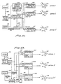
- FIG. 8a An alternate profile memory scheme to that of the circuit of Figure 7 is shown in Figure 8a.
- the programmable controllers 127 are each identical to the programmable controller 127 of Figures 4, 5 and 6 except that the profile memory 155 is not a PROM or ROM but a random access memory (RAM) 155A which is loaded with profile information from the profile memory 603 holding a plurality of different profiles 605.
- RAM random access memory
- each electronically controlled and electrically operated GCDA forming multi-section operation operates completely independently, the one addition exception to this being that each individual GCDA's operation is sequenced by the time sequencing individual reset signals 149 to each individual controller 127.
- a sequence multiplexor 617 receives an instruction 615 from the operator console defining the order of operation of each section (1 through "n") GCDA. This sequencing is controlled by the timed distribution of a reset signal 149 to ech controller 127.
- FIG. 8b Another profile memory scheme to that of the circuit of Figure 7 is shown in Figure 8b.
- the feeder 103, drive shaft 105, anglular position signal generator 123, signals 125, operator console 129, sequence multiplexor 617, sequence instructions 615, time-sequenced plural reset sigals 149 are as described above in connection with Figure 8a.
- the plurality of identical programmable controllers 303 differ from those previous controllers 127 with their loadable RAM's 155A, in that each controller 303 here contains its own profile memory 603 comprising the profiles (A) through (Q) 605, each being stored in separate idividual ROMS or PROMS which can be identical to the memory 155.
- the operator console 129 provides a profile use instruction 305 to each controller 303 library 603 to make a particular memory 155 hold profile 605 out of the controller 303 until changed.
- This scheme provides the advantage with duplication of memories 155 and profiles 605 that a loss of memory component in one controller 303 section will not impair or inhibit operation of other controller 303 sections (1) through (n).
Landscapes
- Engineering & Computer Science (AREA)
- Chemical & Material Sciences (AREA)
- Materials Engineering (AREA)
- Organic Chemistry (AREA)
- Manufacturing & Machinery (AREA)
- Mechanical Engineering (AREA)
- Physics & Mathematics (AREA)
- General Physics & Mathematics (AREA)
- Automation & Control Theory (AREA)
- Control Of Position Or Direction (AREA)
- Control Of Stepping Motors (AREA)
- Specific Conveyance Elements (AREA)
- Control Of Multiple Motors (AREA)
- Manipulator (AREA)
Claims (54)
Applications Claiming Priority (2)
| Application Number | Priority Date | Filing Date | Title |
|---|---|---|---|
| US186440 | 1980-09-12 | ||
| US06/186,440 US4313750A (en) | 1980-09-12 | 1980-09-12 | Electronically controlled robot for handling glassware |
Publications (3)
| Publication Number | Publication Date |
|---|---|
| EP0048133A1 EP0048133A1 (de) | 1982-03-24 |
| EP0048133B1 EP0048133B1 (de) | 1985-06-19 |
| EP0048133B2 true EP0048133B2 (de) | 1988-10-12 |
Family
ID=22684969
Family Applications (1)
| Application Number | Title | Priority Date | Filing Date |
|---|---|---|---|
| EP81304144A Expired EP0048133B2 (de) | 1980-09-12 | 1981-09-10 | Elektronische Handhabung von Glasgegenständen |
Country Status (7)
| Country | Link |
|---|---|
| US (1) | US4313750A (de) |
| EP (1) | EP0048133B2 (de) |
| JP (1) | JPS5781020A (de) |
| KR (1) | KR860000281B1 (de) |
| AU (1) | AU557529B2 (de) |
| CA (1) | CA1184628A (de) |
| DE (1) | DE3171035D1 (de) |
Families Citing this family (23)
| Publication number | Priority date | Publication date | Assignee | Title |
|---|---|---|---|---|
| MX148331A (es) * | 1980-10-27 | 1983-04-11 | Invest Fic Fideicomiso | Mejoras en control electronico para sacador de articulos en maquinas de fabricacion de articulos de vidrio u otros materiales |
| GB2094780B (en) * | 1981-02-27 | 1984-09-19 | Emhart Uk Ltd | Glassware forming machines and processes for operating such machines |
| GB2093824B (en) * | 1981-02-27 | 1984-09-19 | Emhart Uk Ltd | Glassware forming machines and processes for operating such machines |
| US4462519A (en) * | 1982-08-03 | 1984-07-31 | Maul Technology Corporation | Glass container pusher |
| US4529429A (en) * | 1983-05-06 | 1985-07-16 | Ball Corporation | Digital glass forming machine |
| AU568676B2 (en) * | 1983-08-04 | 1988-01-07 | Emhart Glass Machinery Investments Inc. | Glass pusher |
| US4562753A (en) * | 1983-08-31 | 1986-01-07 | Emhart Industries, Inc. | Apparatus for adjusting individual cams of a pusher conveyor |
| DE3335850C2 (de) * | 1983-10-03 | 1986-11-06 | Fränkische Rohrwerke Gebrüder Kirchner GmbH & Co, 8729 Königsberg | Vorrichtung zum Herstellen von Kunststoffrohren |
| US4548637A (en) * | 1984-08-30 | 1985-10-22 | Owens-Illinois, Inc. | Servo-control of machine motions in manufacture of glass containers |
| GB2166265B (en) * | 1984-10-27 | 1988-02-24 | Emhart Ind | Control of apparatus for use in the manufacture of glassware articles |
| US4613353A (en) * | 1985-04-17 | 1986-09-23 | Emhart Industries, Inc. | Convoluted shaft actuator link for glassware forming machine |
| US4685947A (en) * | 1985-09-12 | 1987-08-11 | Emhart Industries, Inc. | Glassware forming apparatus with distributed control and method of operation |
| US4708727A (en) * | 1986-11-14 | 1987-11-24 | Vitro Tec Fideicomiso | Method and apparatus for synchronizing the velocity of a 90 degree push-out apparatus and of the carrier converyor in an I.S. glassware forming machine |
| GB8711824D0 (en) * | 1987-05-19 | 1987-06-24 | Emhart Ind | Control of pusher mechanisms |
| US4923499A (en) * | 1988-06-10 | 1990-05-08 | Maul Technology Corporation | Article transfer mechanism |
| US5098458A (en) * | 1988-06-10 | 1992-03-24 | Vhc, Ltd. | Article transfer mechanism |
| ATE114616T1 (de) * | 1989-10-27 | 1994-12-15 | Vhc Ltd | Weitergabemechanismus für glaswaren. |
| US5125499A (en) * | 1989-10-27 | 1992-06-30 | Vhc, Ltd. | Article transfer mechanism |
| FR2716548B1 (fr) * | 1994-02-22 | 1996-08-30 | Vidrala Sa | Système informatisé d'actionnement rotatif pour le déplacement synchronisé de différents produits notamment des récipients en verre. |
| US5950799A (en) * | 1996-12-24 | 1999-09-14 | Owens-Brockway Glass Container Inc. | Generation of lehr loader motion profile in an individual section glassware forming system |
| US5779749A (en) * | 1997-04-21 | 1998-07-14 | Owens-Brockway Glass Container Inc. | Generation of needle motion profile in an individual section glassware forming system |
| US5818190A (en) * | 1997-05-16 | 1998-10-06 | Emhart Glass Machinery Investments Inc. | Programmable electronic clutch for I.S. machine |
| US5904745A (en) * | 1997-05-19 | 1999-05-18 | Owens-Brockway Glass Container Inc. | Generation of sweepout motion profile in an individual section glassware forming system |
Family Cites Families (7)
| Publication number | Priority date | Publication date | Assignee | Title |
|---|---|---|---|---|
| US3476266A (en) * | 1967-11-28 | 1969-11-04 | George C Devol | Binary-code controlled apparatus |
| US3851769A (en) * | 1971-04-09 | 1974-12-03 | Seiko Instr & Electronics | Industrial robot |
| US3951271A (en) * | 1974-05-03 | 1976-04-20 | Mette Klaus Hermann | Robot control device |
| US4007028A (en) * | 1975-09-30 | 1977-02-08 | Reliance Electric Company | Electronically controlled glassware-forming machine |
| DE2656433C3 (de) * | 1976-12-14 | 1983-11-17 | Fraunhofer-Gesellschaft Zur Foerderung Der Angewandten Forschung E.V., 8000 Muenchen | Verfahren und Anordnung zur Regelung von Manipulatoen und industriellen Robotern |
| DE2746675C2 (de) * | 1977-10-18 | 1979-10-04 | Hermann Heye, 3063 Obernkirchen | Glasformmaschine mit mehreren Stationen |
| US4247317A (en) * | 1978-04-20 | 1981-01-27 | Ball Corporation | Glassware forming machine computer-ram controller system |
-
1980
- 1980-09-12 US US06/186,440 patent/US4313750A/en not_active Expired - Lifetime
-
1981
- 1981-08-20 CA CA000384281A patent/CA1184628A/en not_active Expired
- 1981-09-08 AU AU75043/81A patent/AU557529B2/en not_active Ceased
- 1981-09-09 KR KR8103397A patent/KR860000281B1/ko not_active Expired
- 1981-09-10 DE DE8181304144T patent/DE3171035D1/de not_active Expired
- 1981-09-10 EP EP81304144A patent/EP0048133B2/de not_active Expired
- 1981-09-12 JP JP56143186A patent/JPS5781020A/ja active Pending
Also Published As
| Publication number | Publication date |
|---|---|
| CA1184628A (en) | 1985-03-26 |
| KR860000281B1 (en) | 1986-03-26 |
| EP0048133B1 (de) | 1985-06-19 |
| DE3171035D1 (en) | 1985-07-25 |
| AU7504381A (en) | 1982-03-18 |
| EP0048133A1 (de) | 1982-03-24 |
| JPS5781020A (en) | 1982-05-20 |
| KR830007397A (ko) | 1983-10-21 |
| US4313750A (en) | 1982-02-02 |
| AU557529B2 (en) | 1986-12-24 |
Similar Documents
| Publication | Publication Date | Title |
|---|---|---|
| EP0048133B2 (de) | Elektronische Handhabung von Glasgegenständen | |
| EP0215633B1 (de) | Elektronische Steuervorrichtung für eine Glaswarenbearbeitungsmaschine | |
| US4152134A (en) | Electronic control system for an individual section glassware forming machine | |
| US5125499A (en) | Article transfer mechanism | |
| US4203752A (en) | Multi-station glass-forming machine | |
| CA1235215A (en) | Digital glass forming machine | |
| US4469993A (en) | Programmable multiple position machine | |
| US5038915A (en) | Article synchronizing apparatus for wrapping or boxing machines | |
| US5431274A (en) | Rotary electronic profile placer | |
| EP0100239B1 (de) | Verfahren und Vorrichtung zur Regelung der Zuführung von Glasposten zu einer Glasformmaschine | |
| EP0004905A1 (de) | Computer-RAM-Steuerungssystem für ein Verfahren und eine Vorrichtung zur Herstellung von Glaswaren | |
| DK168678B1 (da) | Styresystem til en værktøjsmaskine og fremgangsmåde til maskinel bearbejdning af et roterende arbejdsstykke | |
| CA1122302A (en) | Numerical control resolver position measuring device | |
| US4409013A (en) | 90 Degree push-out for glassware forming machines and electronic control for the same | |
| US6366045B1 (en) | Operating-cycle synchronized engagement and disengagement of servo axle groups by means of electronically simulated cam disks | |
| US3767374A (en) | Glass ware reject apparatus | |
| GB2087106A (en) | Improved control system for a glassware forming machine | |
| EP0425114B1 (de) | Weitergabemechanismus für Glaswaren | |
| EP0268414B1 (de) | Elektronische Servosteuerung der Glastropfen-Verteilung | |
| EP0037799B1 (de) | Schieber, um Gegenstände von einer Produktionsmaschine, bestehend aus individuellen Segmenten, wegzubewegen | |
| US5061309A (en) | Multiple row pusher system for glass forming machine | |
| US4923499A (en) | Article transfer mechanism | |
| US4382810A (en) | Programmable speed controller | |
| US4145205A (en) | Timing pulse generator for a glassware forming machine | |
| JP2608028B2 (ja) | ガラス製品成形機用制御装置 |
Legal Events
| Date | Code | Title | Description |
|---|---|---|---|
| PUAI | Public reference made under article 153(3) epc to a published international application that has entered the european phase |
Free format text: ORIGINAL CODE: 0009012 |
|
| AK | Designated contracting states |
Designated state(s): BE CH DE FR GB IT LU NL SE |
|
| 17P | Request for examination filed |
Effective date: 19820903 |
|
| ITF | It: translation for a ep patent filed | ||
| GRAA | (expected) grant |
Free format text: ORIGINAL CODE: 0009210 |
|
| AK | Designated contracting states |
Designated state(s): BE CH DE FR GB IT LI LU NL SE |
|
| REF | Corresponds to: |
Ref document number: 3171035 Country of ref document: DE Date of ref document: 19850725 |
|
| ET | Fr: translation filed | ||
| PG25 | Lapsed in a contracting state [announced via postgrant information from national office to epo] |
Ref country code: LU Free format text: LAPSE BECAUSE OF NON-PAYMENT OF DUE FEES Effective date: 19850930 |
|
| PLBI | Opposition filed |
Free format text: ORIGINAL CODE: 0009260 |
|
| 26 | Opposition filed |
Opponent name: FIRMA HERMANN HEYE Effective date: 19860312 |
|
| NLR1 | Nl: opposition has been filed with the epo |
Opponent name: FIRMA HERMANN HEYE |
|
| PGFP | Annual fee paid to national office [announced via postgrant information from national office to epo] |
Ref country code: NL Payment date: 19870930 Year of fee payment: 7 |
|
| PUAH | Patent maintained in amended form |
Free format text: ORIGINAL CODE: 0009272 |
|
| STAA | Information on the status of an ep patent application or granted ep patent |
Free format text: STATUS: PATENT MAINTAINED AS AMENDED |
|
| PG25 | Lapsed in a contracting state [announced via postgrant information from national office to epo] |
Ref country code: LI Effective date: 19880930 Ref country code: CH Effective date: 19880930 |
|
| 27A | Patent maintained in amended form |
Effective date: 19881012 |
|
| AK | Designated contracting states |
Kind code of ref document: B2 Designated state(s): BE CH DE FR GB IT LU NL SE |
|
| PG25 | Lapsed in a contracting state [announced via postgrant information from national office to epo] |
Ref country code: SE Effective date: 19881012 Ref country code: NL Effective date: 19881012 |
|
| NLR2 | Nl: decision of opposition | ||
| ET3 | Fr: translation filed ** decision concerning opposition | ||
| NLV1 | Nl: lapsed or annulled due to failure to fulfill the requirements of art. 29p and 29m of the patents act | ||
| REG | Reference to a national code |
Ref country code: CH Ref legal event code: PL |
|
| PGFP | Annual fee paid to national office [announced via postgrant information from national office to epo] |
Ref country code: FR Payment date: 19890926 Year of fee payment: 9 |
|
| PGFP | Annual fee paid to national office [announced via postgrant information from national office to epo] |
Ref country code: SE Payment date: 19890927 Year of fee payment: 9 |
|
| PGFP | Annual fee paid to national office [announced via postgrant information from national office to epo] |
Ref country code: BE Payment date: 19890929 Year of fee payment: 9 |
|
| PGFP | Annual fee paid to national office [announced via postgrant information from national office to epo] |
Ref country code: GB Payment date: 19890930 Year of fee payment: 9 |
|
| PGFP | Annual fee paid to national office [announced via postgrant information from national office to epo] |
Ref country code: DE Payment date: 19891002 Year of fee payment: 9 |
|
| PG25 | Lapsed in a contracting state [announced via postgrant information from national office to epo] |
Ref country code: GB Effective date: 19900910 |
|
| PG25 | Lapsed in a contracting state [announced via postgrant information from national office to epo] |
Ref country code: BE Effective date: 19900930 |
|
| BERE | Be: lapsed |
Owner name: CSS INTERNATIONAL CORP. Effective date: 19900930 |
|
| GBPC | Gb: european patent ceased through non-payment of renewal fee | ||
| PG25 | Lapsed in a contracting state [announced via postgrant information from national office to epo] |
Ref country code: FR Effective date: 19910530 |
|
| PG25 | Lapsed in a contracting state [announced via postgrant information from national office to epo] |
Ref country code: DE Effective date: 19910601 |
|
| REG | Reference to a national code |
Ref country code: FR Ref legal event code: ST |
|
| EUG | Se: european patent has lapsed |
Ref document number: 81304144.9 Effective date: 19890717 |