EP0047609A2 - Ink jet head - Google Patents
Ink jet head Download PDFInfo
- Publication number
- EP0047609A2 EP0047609A2 EP81303903A EP81303903A EP0047609A2 EP 0047609 A2 EP0047609 A2 EP 0047609A2 EP 81303903 A EP81303903 A EP 81303903A EP 81303903 A EP81303903 A EP 81303903A EP 0047609 A2 EP0047609 A2 EP 0047609A2
- Authority
- EP
- European Patent Office
- Prior art keywords
- ink
- nozzle
- head
- nozzles
- ink jet
- Prior art date
- Legal status (The legal status is an assumption and is not a legal conclusion. Google has not performed a legal analysis and makes no representation as to the accuracy of the status listed.)
- Granted
Links
Images


Classifications
-
- B—PERFORMING OPERATIONS; TRANSPORTING
- B41—PRINTING; LINING MACHINES; TYPEWRITERS; STAMPS
- B41J—TYPEWRITERS; SELECTIVE PRINTING MECHANISMS, i.e. MECHANISMS PRINTING OTHERWISE THAN FROM A FORME; CORRECTION OF TYPOGRAPHICAL ERRORS
- B41J2/00—Typewriters or selective printing mechanisms characterised by the printing or marking process for which they are designed
- B41J2/005—Typewriters or selective printing mechanisms characterised by the printing or marking process for which they are designed characterised by bringing liquid or particles selectively into contact with a printing material
- B41J2/01—Ink jet
- B41J2/135—Nozzles
- B41J2/14—Structure thereof only for on-demand ink jet heads
- B41J2/14201—Structure of print heads with piezoelectric elements
- B41J2/14233—Structure of print heads with piezoelectric elements of film type, deformed by bending and disposed on a diaphragm
-
- B—PERFORMING OPERATIONS; TRANSPORTING
- B41—PRINTING; LINING MACHINES; TYPEWRITERS; STAMPS
- B41J—TYPEWRITERS; SELECTIVE PRINTING MECHANISMS, i.e. MECHANISMS PRINTING OTHERWISE THAN FROM A FORME; CORRECTION OF TYPOGRAPHICAL ERRORS
- B41J2/00—Typewriters or selective printing mechanisms characterised by the printing or marking process for which they are designed
- B41J2/005—Typewriters or selective printing mechanisms characterised by the printing or marking process for which they are designed characterised by bringing liquid or particles selectively into contact with a printing material
- B41J2/01—Ink jet
- B41J2/135—Nozzles
- B41J2/14—Structure thereof only for on-demand ink jet heads
- B41J2002/14379—Edge shooter
Definitions
- This invention relates to an ink jet head for use in a printer and relates more particularly to an ink on demand type ink jet head in which ink droplets are jetted out through a nozzle or nozzles for printing.
- an ink jet head for use in a printer, the head having at least one ink flow path therein which comprises an ink supply path, a pressure chamber and a nozzle, the front end face of the or each said nozzle being disposed substantially perpendicular to the nozzle jet axis; the or each pressure chamber having a piezo-electric element associated therewith which is operable to alter the volume of the pressure chamber to cause ink droplets to be jetted out of the, or the respective, nozzle, characterised in that means are provided to cause the ink droplets which are jetted out from the or each said nozzle to be jetted along a line which is parallel to the longitudinal jet axis of the. nozzle.
- the outer end of the or each said nozzle may be provided with an auxiliary ring whose central hole has a diameter equal to that of the nozzle.
- the head may comprise two members between which the or each ink flow path is formed.
- the front end face of one of the members may have a cut-away portion such that the thicknesses of the two members at the front end face of the nozzle are substantially equal.
- one of the members may have an outer end portion which extends outwardly of the other member.
- the head is a multi-nozzle head having spaced groups of nozzles arranged respectively adjacent opposite sides of the head.
- the head may be provided with an ink non-affinity layer or with a recess between said groups of nozzles to prevent ink layers which are built up in use about the outlet ends of said groups of nozzles from contacting each other.
- the distance between each nozzle and the adjacent edge of the head is substantially equal to the distance between each nozzle and the adjacent edge of the ink non-affinity layer or recess.
- the distance between each nozzle and the adjacent edge of the head is at least 0.3mm.
- the head may comprise a head substrate opposite sides of which are secured to vibration plates, the head substrate and vibration plates being formed to provide the said ink flow paths therebetween.
- an auxiliary plate may be secured to the external surface of each vibration plate adjacent to the respective nozzles so as to provide an increased area over which may spread the ink layer which is formed in use about the outlet ends of the said nozzles.
- the ratio of the thickness of each vibration plate to the thickness of the head substrate is at least 1.0.
- reference numeral 1 designates an electromechanical transducer having piezo-electric elements 2 and 3.
- the transducer 1 is disposed in a recess 4 formed in a substrate 10, and the transducer 1 thus forms one side wall of a pressure chamber 7.
- reference numeral 5 designates a substrate which is secured to the substrate lO and which includes an ink supplying path 6, a part of the pressure chamber 7 and a nozzle 9.
- the substrates 5 and lO together form an ink jet head.
- the transducer 1 is displaced as indicated by the chain dotted line to thereby decrease the volume of the pressure chamber 7 and to jet an ink droplet out through the nozzle 9. This is the fundamental principle of the ink-on-demand type ink jet head.
- reference numeral 14 designates a piezo-electric element; 17 a first presure chamber which communicates through a path 11 with a second pressure chamber 19 and with a nozzle 13; and 12 ink supplying paths for supplying ink from an ink tank (not shown) to the second pressure chamber 19.
- the piezo-electric element 14 is driven to decrease the volume of the first ; pressure chamber 17 so that ink in the first pressure chamber 17 is caused to pass through the path 11 and through the second pressure chamber 19 and then to be jetted in the form of droplets from the nozzle 13.
- This is the fundamental principle of a so-called "double-cavity" system.
- the ink jet head of Figure 3 comprises, a pressure chamber 23, which is formed deeper in a head substrate 21 than an ink supplying path 22, and a nozzle 24.
- This ink jet head is formed by a photo-etching technique or the like, preferably by a two-step etching technique.
- a flat substrate 25 is joined to the head substrate 21 by welding or bonding to form the ink jet head.
- a piezo-electric element 26 is provided on the flat substrate 25 in alignment with the pressure chamber 23, and input terminals 27 are provided for the piezo-electric element 26.
- ink droplets are jetted from the nozzle 24 to achieve printing.
- an ink layer 28 is formed on a front end face 20 of the nozzle 24, which front end face 20 is disposed substantially perpendicular to the nozzle jet axis, and by the surface tension of the ink layer 28 an ink droplet 29 is jetted along a line 31 inclined downwardly with respect to a line 30 parallel to the ink jet axis.
- the inclination of the line 31 is determined by the thickness of the ink layer 28, the velocity of the ink droplet 29 and the characteristics of the ink.
- the quality of the printing achieved by the ink jet head of Figure 3 is liable to be unsatisfactory in that the printing intervals are not regular because the ink droplets are jetted along a slanted axis. Furthermore, it is necessary with this ink jet head for the nozzle 24 to be set as close to the printing sheet (not shown) as possible in order to minimize dot shift.
- An ink-on-demand type ink jet head can be readily constructed in the form of a multi-nozzle type ink jet head.
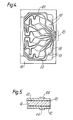
- three side walls are formed for each ink flow path on opposite sides of a head substrate 41 while the remaining side wall is formed by securing a vibration plate 42 to each of the opposite sides of the head substrate 41 in such a way that a group of nozzles 45 are formed.
- Piezo-electric elements 44 are bonded to the vibration plates 42 in alignment with the respective pressure chambers 43 in ink flow paths 50.
- the ink flow paths 50 comprise ink supply paths 49, the pressure chambers 43 and the nozzles 45. Ink droplets are jetted through the group of nozzles 45 by applying a voltage to the piezo-electric elements 44 to achieve printing.
- an ink layer 46 is formed on a front end face 47 of the group of nozzles 45 as shown in Figure 6(a).
- the surface tension of the ink layer 46 causes the ink droplets,which have been jetted out of the groups of nozzles 45, to travel outwardly from the nozzles 45 in the form of ink droplets 52a which pass along inclined lines 52 which are inclined inwardly of the jet axes 51.
- the angle of inclination is determined by the thickness of the ink layer 46, the velocity of the ink droplets 51a and the characteristics of the ink.
- An object of the present invention is therefore to provide an ink jet head in which the above-described difficulties have been eliminated, that is, in which no dot shift occurs and in which the distance between the nozzle and the printing sheet can be made longer.
- FIG. 7 A first embodiment of the present invention is shown in Figure 7 in which those components which have been previously described with reference to Figure 3 are given similar numbers.
- An auxiliary ring 33 having a small central hole 32 whose diameter is equal to that of the nozzle 24 is coupled to the front end face of the nozzle 24.
- the provision of the auxiliary ring 33 makes the ink layer 28 uniform around the nozzle jet axis. Accordingly, the ink droplet 29 passes only along the line 30, which is an extension of the nozzle jet axis, and very little dot shift is caused.
- an ink droplet having a speed of 5 m/s would have a shift of 80 ⁇ m after it had moved 2 mm, while an ink droplet having a speed of 3 m/s would have a shift of 400 ⁇ .m, after it had moved 2mm.
- an auxiliary ring 33 is provided in which the difference between the inside and outside diameters of the ring is at least 0.3 mm, then the ink droplets 29 have very little shift and hence very little dot shift is caused.
- an auxiliary ring 33 is employed.
- the invention is not limited thereto or thereby. That is, the same effect can be obtained by using auxiliary plates having thicknesses t l , t 2 which are substantially equal to each other.
- a portion 21a of the front end face of the head substrate 21 where the nozzle is formed may be cut away as shown in Figure 8 so that t and t may be maintained substantially equal to each other. In any case, all that is necessary is to modify the nozzle front end face 20 so as to maintain t 1 and t substantially equal to each other.
- FIG 9 Another embodiment of the invention is shown in Figure 9 in which those components which have been described with reference to Figures 3 and 4 are similarly numbered.
- the flat substrate 25 which forms the upper surface of the nozzle 24 has an outer end portion 25a which extends by a distance t beyond the head substrate 21 which forms the lower surface of the nozzle 24, as a result of which the ink layer 28 is uniform around the nozzle jet axis.
- an ink droplet 29 passes along the extension line 30 of the nozzle jet axis, so that very little dot shift is caused.
- the dimension t 3 which relates to the thickness of the ink layer 28, the velocity of the ink droplet 29, the characteristics of the ink and the structure of the head, cannot be readily determined. However, generally the dimension t 3 should be larger than zero (t 3 > 0).
- the ink jet head is so designed that ink droplets pass along a line which is an extension of the nozzle jet axis, according to the invention.
- the ink jet head of the invention can print letten, characters and other indicia with a high print quality and is free from dot shift.
- Figures 7 - 9 relate to single nozzle ink jet heads.
- Figure 11 is a sectional view of the nozzles of an ink jet head and is taken perpendicularly to the nozzle jet axes.
- the multi-nozzle ink jet head of Figures 10 and 11 is generally similar to that of Figures 4 and 5, like reference numerals indicating like parts.
- a nozzle 45 and a filter (not shown) of about 20 to 30p m in depth are formed by the use of a two-step etching method.
- a vibration plate 42 having a thickness t 4 of about 0.1 to 0.3 mm is thermally fused to each side of the head substrate 41.
- the front end face 47 of the nozzles is polished. and is formed substantially perpendicularly to the nozzle jet axes.
- the nozzles 45 are arranged on opposite sides of the head substrate 41 so that one group of nozzles 45 is formed in a line on one side of the head substrate 41 and the other group of nozzles 45 is formed in a line on the other side of the head substrate 41.
- An ink non-affinity layer 71 is provided on the central region of the head substrate 41, which central region is flush with the nozzle front end face 47 and is disposed between the groups of nozzles 45.
- the ink non-affinity layer 71 is thus provided on the head between the group of nozzles 45 to prevent the ink layers 46 from contacting each other.
- Figure 11 is a front view of the nozzle front end face 47.
- the width of the ink non-affinity layer 71 is such that the distance t 4 between a nozzle 45 and the outer edge of the vibration plate 42 (i.e. the distance between the nozzle 45 and the outer edge of the front end face 47) is substantially equal to the distance t 5 between the nozzle and the edge of the ink non-affinity layer 71. Therefore, a plane which is tangential to the intersection of the interface between the ink layer 46 and the air and the nozzle jet axis is substantially parallel to the nozzle front end face 47, as shown in Figure 11. Accordingly, the nozzle jet axis is not inclined and dot shift is not caused.
- the ink non-affinity layer 71 can be readily formed by coating, spraying or vacuum-depositing a plastics material such as that sold under the Trade Mark TEFLON.
- the nozzles 45 are spaced by an integral number of times of the spacing between dots in a horizontal row of printing dots, vertical printing dots are shifted by a half pitch, and the ink non-affinity layer 71 is formed continuously.
- a vibration plate 42 forms one side wall of each nozzle 45.
- at least one side wall of a nozzle 45 may be formed with a different material.
- ink flow paths are formed on both of the opposite sides of the head substrate 41, although the ink flow paths may be formed in the vibration plates 42 or may be formed in both the head substrate 41 and the vibration plates 42.
- a plane tangential to the intersection of the ink jet axis and the ink layer is substantially parallel to the nozzle front end face 47, and accordingly the ink jet axes are not inclined from their normal directions for jetting ink droplets.
- FIG. 12 A further embodiment of the invention is shown in Figure 12 which is similar to the embodiment of Figures 10 and 11 except that, instead of (or, if desired, in addition to) providing the ink non-affinity layer 71, a recess 70 is cut in the central region of the nozzle front end face 47 of the head substrate between the groups of nozzles 45 and in such a manner that the remaining thickness t 7 is substantially equal to the thickness t 6 of the vibration plates 42. That is to say, the distance t 6 between each nozzle 45 and the outer edge of the nozzle front end face 47 is substantially equal to the distance t 7 between each nozzle 45 and the adjacent edge of the recess 70.
- a plane tangential to the intersection of the ink layer 46 and the nozzle jet axis is substantially parallel to the nozzle front end face 47. Accordingly, the surface tension of the ink layer acts equally on the ink droplets and therefore the ink droplets are jetted out in the normal direction and dot shift is not caused.
- the depth of the recess 70 should be such that, even when the ink layers 46 flow into the recess 70 when their volumes increase, the ink layers 46 for two groups of nozzles are not connected to each other through the recess 70.
- auxiliary plates 72 are thermally fused to the vibration plates 42 in the vicinity of the nozzles 45 so as to provide an increased area over which the ink layer 46 may spread.
- the auxiliary plates 72 and the nozzle front end face 47 are polished simultaneously so that a thin ink layer 46 can spread to the ends of the auxiliary plates 72. That is, to say, the ink layer 46 is uniformly formed on the nozzle jet axes. Accordingly, the ink droplets are jetted straight along the nozzles jet axes, and no dot shift is caused.
- the auxiliary plates 72 are thermally fused to the external surfaces of the vibration plates 42.
- the same result can be obtained by increasing the thickness of the portion of each vibration plate 42 which forms the respective nozzle while the thickness of the portion of the vibration plate 42 to which only the piezo-electric element 44 is bonded is decreased.
- the nozzles 45 can readily be made flat by polishing, and the nozzles 45 can be readily covered with a lid.
- the distance between an outer end of the nozzle front end face 47 and the adjacent nozzles 45 may be at least 0.3 mm.
- the nozzle front end face 47 can be shaped as described above by forming at least one side wall of the two flow paths near the pressure chamber by the vibration plate 42 and by forming at least one side wall of the nozzle 45 by a different material.
- the ink flow paths are formed in the head substrate 41.
- the ink flow paths may be formed in the vibration plates 42 or may be formed in both the vibration plates 42 and the head substrate 41.
- FIG. 14 A further embodiment of the invention is shown in Figure 14 in a sectional view.
- Ink flow paths 50 having a pattern similar to that shown in Figure 1 are formed on opposite sides of a glass head substrate 41 (having a thickness of 0.3 mm) by photo-etching (the etching depth being about 100 pm).
- a nozzle 45 and a filter having a depth of about 20 to 30 1 im are formed by a two-step etching process.
- a vibration plate42 having a thickness t 9 of 0.3 to 1.0 mm is thermally fused to the head substrate 41.
- the distance t between an outer end of the nozzle front end face 47 and the adjacent nozzles 45 is at least 0.3 mm.
- the nozzle front end face 47 is polished.
- Piezo-electric elements (not shown) are bonded to the vibration plates 42 and electrodes (not shown) are connected to the piezo-electric elements.
- the head thus constructed was tested by varying the thickness t 8 of the head substrate 41 and by varying the thickness t of the vibration plates 42.
- the ink used had a surface tension of 45 dyn/cm and a viscosity of 1.8 c.p., and the velocity of the ink droplets was about 3 to 5 m/s.
- the results of the test are indicated graphically in Figure 15. As is apparent from Figure 15, when the ratio t 9/ t 8 of the vibration plate thickness t to the head substrate thickness t 8 is at least 1.0, very little dot shift is caused.
- the interface between the ink layer 46 and the air in Figure 14 is substantially perpendicular to the nozzle jet axes, and therefore the surface tension acts substantially equally on the ink droplets to the right and left. This allows the ink droplets to be jetted out straight.
- the ink flow paths are described as being formed in the head substrate 41 by etching. However, they may be formed in the vibration plates 42 or may be formed in both the head substrate 41 and in the vibration plates 42.
- the thickness of the head may be controlled by placing a different material on the vibration plate 42 which forms one side wall of each nozzle 45, or one side wall of each nozzle may be formed using a different material.
- an ink jet head in which no dot shift . is caused and in which printing can be carried out with a high density and high print quality is provided by the invention. Moreover, the jetting of the ink droplets is carried out without producing air bubbles in the nozzles.
Abstract
Description
- This invention relates to an ink jet head for use in a printer and relates more particularly to an ink on demand type ink jet head in which ink droplets are jetted out through a nozzle or nozzles for printing.
- According to the present invention, there is provided an ink jet head for use in a printer, the head having at least one ink flow path therein which comprises an ink supply path, a pressure chamber and a nozzle, the front end face of the or each said nozzle being disposed substantially perpendicular to the nozzle jet axis; the or each pressure chamber having a piezo-electric element associated therewith which is operable to alter the volume of the pressure chamber to cause ink droplets to be jetted out of the, or the respective, nozzle, characterised in that means are provided to cause the ink droplets which are jetted out from the or each said nozzle to be jetted along a line which is parallel to the longitudinal jet axis of the. nozzle.
- The outer end of the or each said nozzle may be provided with an auxiliary ring whose central hole has a diameter equal to that of the nozzle.
- The head may comprise two members between which the or each ink flow path is formed. The front end face of one of the members may have a cut-away portion such that the thicknesses of the two members at the front end face of the nozzle are substantially equal. Alternatively, one of the members may have an outer end portion which extends outwardly of the other member.
- In one form of the invention, the head is a multi-nozzle head having spaced groups of nozzles arranged respectively adjacent opposite sides of the head.
- Thus the head may be provided with an ink non-affinity layer or with a recess between said groups of nozzles to prevent ink layers which are built up in use about the outlet ends of said groups of nozzles from contacting each other. Preferably, the distance between each nozzle and the adjacent edge of the head is substantially equal to the distance between each nozzle and the adjacent edge of the ink non-affinity layer or recess. Preferably also the distance between each nozzle and the adjacent edge of the head is at least 0.3mm.
- The head may comprise a head substrate opposite sides of which are secured to vibration plates, the head substrate and vibration plates being formed to provide the said ink flow paths therebetween. Moreover, an auxiliary plate may be secured to the external surface of each vibration plate adjacent to the respective nozzles so as to provide an increased area over which may spread the ink layer which is formed in use about the outlet ends of the said nozzles. Preferably, the ratio of the thickness of each vibration plate to the thickness of the head substrate is at least 1.0.
- The invention is illustrated, merely by way of example, in the accompanying drawings, in which:-
- Figures 1 and 2 are sectional views of examples of a conventional ink jet head,
- Figure 3 is a sectional view of an improved conventional ink jet head,
- Figure 4 is a plan view of a known multi-nozzle ink jet head,
- Figure 5 is a sectional view of the ink jet head of Figure 4,
- Figure 6(a) is an enlarged view of a part of the ink jet head of Figures 4 and 5,
- Figure 6(b) and 6(c) are enlarged views of a nozzle portion of the structure shown in Figure 6(a),
- Figures 7 and 8 are sectional views of embodiments of an ink jet head according to the present invention,
- Figure 9 is a sectional view of another embodiment of the present invention,
- Figure lO is a front view of an ink-jet head according to the present invention,
- Figure 11 is a sectional view showing the nozzles and components adjacent thereto of the ink jet head of Figure 10,
- Figures 12-14 are diagrams illustrating further embodiments of multi-nozzle ink jet heads according to the present invention, and
- Figure 15 is a graphical representation of test results on an ink jet head constructed in accordance with the present invention.
- Terms such as "upper" and "lower", as used in the description below, are to be understood to refer to directions as seen in the accompanying drawings.
- A variety of ink-on-demand type ink jet heads have been proposed in the prior art. Typical examples of these are the Kayser system, described in U.S. Patent Specification No. 3,946,398 and the Stemme system, described in U.S. Patent Specification No. 3,747,120.
- The Kayser system will be briefly described with reference to Figure 1. In Figure 1,
reference numeral 1 designates an electromechanical transducer having piezo-electric elements 2 and 3. Thetransducer 1 is disposed in a recess 4 formed in a substrate 10, and thetransducer 1 thus forms one side wall of a pressure chamber 7. Further in Figure 1, reference numeral 5 designates a substrate which is secured to the substrate lO and which includes an ink supplying path 6, a part of the pressure chamber 7 and anozzle 9. The substrates 5 and lO together form an ink jet head. When an input signal is applied toinput terminals 8, thetransducer 1 is displaced as indicated by the chain dotted line to thereby decrease the volume of the pressure chamber 7 and to jet an ink droplet out through thenozzle 9. This is the fundamental principle of the ink-on-demand type ink jet head. - The Stemme system will be discussed briefly with reference to Figure 2. In Figure 2,
reference numeral 14 designates a piezo-electric element; 17 a first presure chamber which communicates through apath 11 with asecond pressure chamber 19 and with anozzle 13; and 12 ink supplying paths for supplying ink from an ink tank (not shown) to thesecond pressure chamber 19. When an input signal is applied to input terminals 18, the piezo-electric element 14 is driven to decrease the volume of the first ; pressure chamber 17 so that ink in the first pressure chamber 17 is caused to pass through thepath 11 and through thesecond pressure chamber 19 and then to be jetted in the form of droplets from thenozzle 13. This is the fundamental principle of a so-called "double-cavity" system. - The conventional systems shown in Figures 1 and 2 are based merely on fundamental principles. In order to provide a practical system, it is necessary to simplify them, to make them easier to mass produce and to decrease the manufacturing cost. An ink jet head as shown in Figure 3 satisfies these requirements.
- The ink jet head of Figure 3 comprises, a
pressure chamber 23, which is formed deeper in ahead substrate 21 than anink supplying path 22, and anozzle 24. This ink jet head is formed by a photo-etching technique or the like, preferably by a two-step etching technique. Aflat substrate 25 is joined to thehead substrate 21 by welding or bonding to form the ink jet head. A piezo-electric element 26 is provided on theflat substrate 25 in alignment with thepressure chamber 23, andinput terminals 27 are provided for the piezo-electric element 26. - When an input voltage signal is applied to the piezo-
electric element 26, ink droplets are jetted from thenozzle 24 to achieve printing. If the printing response frequency exceeds 500 Hz, anink layer 28 is formed on afront end face 20 of thenozzle 24, whichfront end face 20 is disposed substantially perpendicular to the nozzle jet axis, and by the surface tension of theink layer 28 anink droplet 29 is jetted along aline 31 inclined downwardly with respect to aline 30 parallel to the ink jet axis. The inclination of theline 31 is determined by the thickness of theink layer 28, the velocity of theink droplet 29 and the characteristics of the ink. Because of these factors, the quality of the printing achieved by the ink jet head of Figure 3 is liable to be unsatisfactory in that the printing intervals are not regular because the ink droplets are jetted along a slanted axis. Furthermore, it is necessary with this ink jet head for thenozzle 24 to be set as close to the printing sheet (not shown) as possible in order to minimize dot shift. - An ink-on-demand type ink jet head can be readily constructed in the form of a multi-nozzle type ink jet head. As shown in Figures 4 to 6, using a simple technique such as photo-etching, three side walls are formed for each ink flow path on opposite sides of a
head substrate 41 while the remaining side wall is formed by securing avibration plate 42 to each of the opposite sides of thehead substrate 41 in such a way that a group ofnozzles 45 are formed. Piezo-electric elements 44 are bonded to thevibration plates 42 in alignment with therespective pressure chambers 43 inink flow paths 50. Theink flow paths 50 compriseink supply paths 49, thepressure chambers 43 and thenozzles 45. Ink droplets are jetted through the group ofnozzles 45 by applying a voltage to the piezo-electric elements 44 to achieve printing. - If the printing response frequency exceeds 500 Hz, an
ink layer 46 is formed on afront end face 47 of the group ofnozzles 45 as shown in Figure 6(a). As a result, instead ofink droplets 51a being jetted out parallel to the longitudinal axes of thenozzles 45, the surface tension of theink layer 46 causes the ink droplets,which have been jetted out of the groups ofnozzles 45, to travel outwardly from thenozzles 45 in the form of ink droplets 52a which pass alonginclined lines 52 which are inclined inwardly of thejet axes 51. The angle of inclination is determined by the thickness of theink layer 46, the velocity of theink droplets 51a and the characteristics of the ink. Thus, since the ink droplets 52a pass along theinclined lines 52, the conventional multi-nozzle head suffers from the difficulty that printing at regular printing intervals cannot be achieved. - Moreover, in this structure, as shown in Figure 6(b), when the volume of a
pressure chamber 43 increases and thepressure chamber 43 absorbs ink from an ink tank (not shown) after the ink has been jetted out, themeniscus 100 at the top end of therespective nozzle 45 moves to a position inwardly of thenozzle 45 and thereafter stops in a position where the pressure on the ink is balanced by the atmospheric pressure. However, as shown in Figure 6(c), when the amount of ink in theink layer 46 is large, the outlet end of thenozzle 45 is covered with the ink of theink layer 46 and anair bubble 101 may be produced in thenozzle 45. - If there is such an
air bubble 101 in anozzle 45, then when the volume of thepressure chamber 43 is diminished at the next printing, an ink droplet is not jetted out of therespective nozzle 45 and a dot is missed? As a result, letters or other indicia can not be formed properly. - An object of the present invention is therefore to provide an ink jet head in which the above-described difficulties have been eliminated, that is, in which no dot shift occurs and in which the distance between the nozzle and the printing sheet can be made longer.
- A first embodiment of the present invention is shown in Figure 7 in which those components which have been previously described with reference to Figure 3 are given similar numbers. An
auxiliary ring 33 having a smallcentral hole 32 whose diameter is equal to that of thenozzle 24 is coupled to the front end face of thenozzle 24. The provision of theauxiliary ring 33 makes theink layer 28 uniform around the nozzle jet axis. Accordingly, theink droplet 29 passes only along theline 30, which is an extension of the nozzle jet axis, and very little dot shift is caused. - If no
auxiliary ring 33 were provided, an ink droplet having a speed of 5 m/s would have a shift of 80 µ m after it had moved 2 mm, while an ink droplet having a speed of 3 m/s would have a shift of 400 µ.m, after it had moved 2mm. On the other hand, if anauxiliary ring 33 is provided in which the difference between the inside and outside diameters of the ring is at least 0.3 mm, then theink droplets 29 have very little shift and hence very little dot shift is caused. - In the embodiment shown in Figure 7, an
auxiliary ring 33 is employed. However, the invention is not limited thereto or thereby. That is, the same effect can be obtained by using auxiliary plates having thicknesses tl, t2 which are substantially equal to each other. Furthermore, a portion 21a of the front end face of thehead substrate 21 where the nozzle is formed may be cut away as shown in Figure 8 so that t and t may be maintained substantially equal to each other. In any case, all that is necessary is to modify the nozzle front end face 20 so as to maintain t1 and t substantially equal to each other. - Another embodiment of the invention is shown in Figure 9 in which those components which have been described with reference to Figures 3 and 4 are similarly numbered. In this embodiment, the
flat substrate 25 which forms the upper surface of thenozzle 24 has an outer end portion 25a which extends by a distance t beyond thehead substrate 21 which forms the lower surface of thenozzle 24, as a result of which theink layer 28 is uniform around the nozzle jet axis. In this case, anink droplet 29 passes along theextension line 30 of the nozzle jet axis, so that very little dot shift is caused. The dimension t3, which relates to the thickness of theink layer 28, the velocity of theink droplet 29, the characteristics of the ink and the structure of the head, cannot be readily determined. However, generally the dimension t3 should be larger than zero (t3 > 0). - The embodiments of the invention shown in Figures 7 - 9 be readily produced by extruding plastics material, although the configuration of the components around the nozzle is somewhat intricate.
- As is apparent from the above description, the ink jet head is so designed that ink droplets pass along a line which is an extension of the nozzle jet axis, according to the invention. Thus, the ink jet head of the invention can print letten, characters and other indicia with a high print quality and is free from dot shift.
- The embodiment shown in Figures 7 - 9 relate to single nozzle ink jet heads. However, another embodiment of the invention applied to a multi-nozzle type ink jet head is shown in Figures 10 and 11. Figure 11 is a sectional view of the nozzles of an ink jet head and is taken perpendicularly to the nozzle jet axes. The multi-nozzle ink jet head of Figures 10 and 11 is generally similar to that of Figures 4 and 5, like reference numerals indicating like parts.
Ink flow paths 50 which are about 100 µ m in depth are formed on opposite sides of a glass head substrate 41 (having a thickness = 1.27 mm), using a photo-etching technique. In each ink flow path, anozzle 45 and a filter (not shown) of about 20 to 30p m in depth are formed by the use of a two-step etching method. Avibration plate 42 having a thickness t4 of about 0.1 to 0.3 mm is thermally fused to each side of thehead substrate 41. The front end face 47 of the nozzles is polished. and is formed substantially perpendicularly to the nozzle jet axes. Thenozzles 45 are arranged on opposite sides of thehead substrate 41 so that one group ofnozzles 45 is formed in a line on one side of thehead substrate 41 and the other group ofnozzles 45 is formed in a line on the other side of thehead substrate 41. Anink non-affinity layer 71 is provided on the central region of thehead substrate 41, which central region is flush with the nozzlefront end face 47 and is disposed between the groups ofnozzles 45. Theink non-affinity layer 71 is thus provided on the head between the group ofnozzles 45 to prevent the ink layers 46 from contacting each other. - Figure 11 is a front view of the nozzle
front end face 47. The width of theink non-affinity layer 71 is such that the distance t4 between anozzle 45 and the outer edge of the vibration plate 42 (i.e. the distance between thenozzle 45 and the outer edge of the front end face 47) is substantially equal to the distance t5 between the nozzle and the edge of theink non-affinity layer 71. Therefore, a plane which is tangential to the intersection of the interface between theink layer 46 and the air and the nozzle jet axis is substantially parallel to the nozzlefront end face 47, as shown in Figure 11. Accordingly, the nozzle jet axis is not inclined and dot shift is not caused. - If a water-based ink is used in the ink jet head, the
ink non-affinity layer 71 can be readily formed by coating, spraying or vacuum-depositing a plastics material such as that sold under the Trade Mark TEFLON. - In Figure 10, the
nozzles 45 are spaced by an integral number of times of the spacing between dots in a horizontal row of printing dots, vertical printing dots are shifted by a half pitch, and theink non-affinity layer 71 is formed continuously. - In the embodiment of Figures 10 and 11, a
vibration plate 42 forms one side wall of eachnozzle 45. However, at least one side wall of anozzle 45 may be formed with a different material. Furthermore, in the embodiment of Figures 10 and 11, ink flow paths are formed on both of the opposite sides of thehead substrate 41, although the ink flow paths may be formed in thevibration plates 42 or may be formed in both thehead substrate 41 and thevibration plates 42. - As is clear from the above description, a plane tangential to the intersection of the ink jet axis and the ink layer is substantially parallel to the nozzle
front end face 47, and accordingly the ink jet axes are not inclined from their normal directions for jetting ink droplets. Thus, there is produced an ink jet head in which no dot shift occurs and in which printing can be carried out with a high density and high print quality. - A further embodiment of the invention is shown in Figure 12 which is similar to the embodiment of Figures 10 and 11 except that, instead of (or, if desired, in addition to) providing the
ink non-affinity layer 71, a recess 70 is cut in the central region of the nozzle front end face 47 of the head substrate between the groups ofnozzles 45 and in such a manner that the remaining thickness t7 is substantially equal to the thickness t 6 of thevibration plates 42. That is to say, the distance t6 between eachnozzle 45 and the outer edge of the nozzlefront end face 47 is substantially equal to the distance t7 between eachnozzle 45 and the adjacent edge of the recess 70. - When printing is carried out with the ink jet head of Figure 12, a plane tangential to the intersection of the
ink layer 46 and the nozzle jet axis is substantially parallel to the nozzlefront end face 47. Accordingly, the surface tension of the ink layer acts equally on the ink droplets and therefore the ink droplets are jetted out in the normal direction and dot shift is not caused. The depth of the recess 70 should be such that, even when the ink layers 46 flow into the recess 70 when their volumes increase, the ink layers 46 for two groups of nozzles are not connected to each other through the recess 70. - In the embodiment of the invention as shown in Figure 13,
auxiliary plates 72 are thermally fused to thevibration plates 42 in the vicinity of thenozzles 45 so as to provide an increased area over which theink layer 46 may spread. Theauxiliary plates 72 and the nozzlefront end face 47 are polished simultaneously so that athin ink layer 46 can spread to the ends of theauxiliary plates 72. That is, to say, theink layer 46 is uniformly formed on the nozzle jet axes. Accordingly, the ink droplets are jetted straight along the nozzles jet axes, and no dot shift is caused. - In the embodiment of Figure 13, the
auxiliary plates 72 are thermally fused to the external surfaces of thevibration plates 42. However, the same result can be obtained by increasing the thickness of the portion of eachvibration plate 42 which forms the respective nozzle while the thickness of the portion of thevibration plate 42 to which only the piezo-electric element 44 is bonded is decreased. As the width of the nozzlefront end face 47 is increased, thenozzles 45 can readily be made flat by polishing, and thenozzles 45 can be readily covered with a lid. The distance between an outer end of the nozzlefront end face 47 and theadjacent nozzles 45 may be at least 0.3 mm. - The nozzle front end face 47 can be shaped as described above by forming at least one side wall of the two flow paths near the pressure chamber by the
vibration plate 42 and by forming at least one side wall of thenozzle 45 by a different material. In the embodiment of Figure 13, the ink flow paths are formed in thehead substrate 41. However, the ink flow paths may be formed in thevibration plates 42 or may be formed in both thevibration plates 42 and thehead substrate 41. - A further embodiment of the invention is shown in Figure 14 in a sectional view.
Ink flow paths 50 having a pattern similar to that shown in Figure 1 are formed on opposite sides of a glass head substrate 41 (having a thickness of 0.3 mm) by photo-etching (the etching depth being about 100 pm). In eachink flow path 50, anozzle 45 and a filter (not shown) having a depth of about 20 to 301im are formed by a two-step etching process. A vibration plate42 having a thickness t9 of 0.3 to 1.0 mm is thermally fused to thehead substrate 41. Thus, the distance t between an outer end of the nozzlefront end face 47 and theadjacent nozzles 45 is at least 0.3 mm. The nozzlefront end face 47 is polished. Piezo-electric elements (not shown) are bonded to thevibration plates 42 and electrodes (not shown) are connected to the piezo-electric elements. - The head thus constructed was tested by varying the thickness t8 of the
head substrate 41 and by varying the thickness t of thevibration plates 42. The ink used had a surface tension of 45 dyn/cm and a viscosity of 1.8 c.p., and the velocity of the ink droplets was about 3 to 5 m/s. The results of the test are indicated graphically in Figure 15. As is apparent from Figure 15, when the ratio t9/t8 of the vibration plate thickness t to the head substrate thickness t8 is at least 1.0, very little dot shift is caused. In this case, the interface between theink layer 46 and the air in Figure 14 is substantially perpendicular to the nozzle jet axes, and therefore the surface tension acts substantially equally on the ink droplets to the right and left. This allows the ink droplets to be jetted out straight. - In the embodiment of Figure 14, the ink flow paths are described as being formed in the
head substrate 41 by etching. However, they may be formed in thevibration plates 42 or may be formed in both thehead substrate 41 and in thevibration plates 42. - The thickness of the head may be controlled by placing a different material on the
vibration plate 42 which forms one side wall of eachnozzle 45, or one side wall of each nozzle may be formed using a different material. - Thus, an ink jet head in which no dot shift.is caused and in which printing can be carried out with a high density and high print quality is provided by the invention. Moreover, the jetting of the ink droplets is carried out without producing air bubbles in the nozzles.
Claims (16)
Applications Claiming Priority (10)
| Application Number | Priority Date | Filing Date | Title |
|---|---|---|---|
| JP124260/80 | 1980-09-08 | ||
| JP12426080A JPS5749566A (en) | 1980-09-08 | 1980-09-08 | Ink jet head |
| JP12426380A JPS5749569A (en) | 1980-09-08 | 1980-09-08 | Ink jet head |
| JP12426280A JPS5749568A (en) | 1980-09-08 | 1980-09-08 | Ink jet head |
| JP124259/80 | 1980-09-08 | ||
| JP124261/80 | 1980-09-08 | ||
| JP12426180A JPS5749567A (en) | 1980-09-08 | 1980-09-08 | Ink jet head |
| JP124262/80 | 1980-09-08 | ||
| JP124263/80 | 1980-09-08 | ||
| JP12425980A JPS5747670A (en) | 1980-09-08 | 1980-09-08 | Ink jet head |
Publications (3)
| Publication Number | Publication Date |
|---|---|
| EP0047609A2 true EP0047609A2 (en) | 1982-03-17 |
| EP0047609A3 EP0047609A3 (en) | 1983-01-12 |
| EP0047609B1 EP0047609B1 (en) | 1985-06-05 |
Family
ID=27527018
Family Applications (1)
| Application Number | Title | Priority Date | Filing Date |
|---|---|---|---|
| EP81303903A Expired EP0047609B1 (en) | 1980-09-08 | 1981-08-26 | Ink jet head |
Country Status (3)
| Country | Link |
|---|---|
| US (1) | US4420764A (en) |
| EP (1) | EP0047609B1 (en) |
| DE (1) | DE3170847D1 (en) |
Cited By (1)
| Publication number | Priority date | Publication date | Assignee | Title |
|---|---|---|---|---|
| WO2016075447A1 (en) * | 2014-11-14 | 2016-05-19 | The Technology Partnership Plc | Non-contact liquid printing |
Families Citing this family (16)
| Publication number | Priority date | Publication date | Assignee | Title |
|---|---|---|---|---|
| DE3247540A1 (en) * | 1981-12-26 | 1983-07-07 | Konishiroku Photo Industry Co., Ltd., Tokyo | INK PENS |
| US4539569A (en) * | 1982-10-26 | 1985-09-03 | Canon Kabushiki Kaisha | Ink jet recording apparatus |
| US4734706A (en) * | 1986-03-10 | 1988-03-29 | Tektronix, Inc. | Film-protected print head for an ink jet printer or the like |
| DE3787254T2 (en) * | 1986-11-13 | 1994-01-05 | Canon Kk | Process for surface treatment of an ink jet recording head. |
| US4879568A (en) * | 1987-01-10 | 1989-11-07 | Am International, Inc. | Droplet deposition apparatus |
| US5581285A (en) * | 1988-05-13 | 1996-12-03 | Canon Kabushiki Kaisha | Ink jet recording head with discharge opening surface treatment |
| JPH05169666A (en) * | 1991-12-25 | 1993-07-09 | Rohm Co Ltd | Manufacturing ink jet print head |
| JPH05177831A (en) * | 1991-12-27 | 1993-07-20 | Rohm Co Ltd | Ink jet printing head and electronic device equipped therewith |
| JP3147132B2 (en) * | 1992-03-03 | 2001-03-19 | セイコーエプソン株式会社 | Inkjet recording head, diaphragm for inkjet recording head, and method of manufacturing diaphragm for inkjet recording head |
| DE4230292C2 (en) * | 1992-09-10 | 1996-09-19 | Norbert Dr Schwesinger | Inkjet printhead |
| US5381166A (en) * | 1992-11-30 | 1995-01-10 | Hewlett-Packard Company | Ink dot size control for ink transfer printing |
| DE69529317T2 (en) * | 1994-07-29 | 2003-07-10 | Canon Kk | Ink jet printhead, ink jet printhead cartridge, color jet marking apparatus and method for manufacturing the head |
| US5901425A (en) * | 1996-08-27 | 1999-05-11 | Topaz Technologies Inc. | Inkjet print head apparatus |
| US6168265B1 (en) | 1997-03-28 | 2001-01-02 | Brother Kogyo Kabushiki Kaisha | Ink-jet print head |
| US6203139B1 (en) * | 1997-12-05 | 2001-03-20 | Hewlett-Packard Company | Carriage random vibration |
| US20060174502A1 (en) * | 2005-02-09 | 2006-08-10 | Stephen Crane | Linear and angular measuring apparatus |
Citations (5)
| Publication number | Priority date | Publication date | Assignee | Title |
|---|---|---|---|---|
| CH363667A (en) * | 1960-01-11 | 1962-08-15 | Paillard Sa | Thin-walled nozzle, especially for writing device using inkjet |
| CH543135A (en) * | 1971-10-07 | 1973-10-15 | Casio Computer Co Ltd | Inkjet writing instrument |
| DE2362576B1 (en) * | 1973-12-17 | 1975-02-27 | Olympia Werke Ag, 2940 Wilhelmshaven | Device for preventing the leakage of ink from an ink-jet writing mechanism |
| DE2842538A1 (en) * | 1977-10-01 | 1979-04-12 | Canon Kk | METHOD AND DEVICE FOR IMAGE GENERATION |
| DE2949808A1 (en) * | 1978-12-11 | 1980-07-10 | Nippon Electric Co | Ink-jet printer using conductive ink - has acceleration electrode mounted clear of nozzle outlet for form convex meniscus and subsequent droplet formation |
Family Cites Families (9)
| Publication number | Priority date | Publication date | Assignee | Title |
|---|---|---|---|---|
| CH425838A (en) * | 1965-09-29 | 1966-12-15 | Paillard Sa | Tubular needle for writing with inkjet |
| JPS4836188Y1 (en) * | 1969-05-19 | 1973-10-30 | ||
| US3946398A (en) * | 1970-06-29 | 1976-03-23 | Silonics, Inc. | Method and apparatus for recording with writing fluids and drop projection means therefor |
| SE349676B (en) * | 1971-01-11 | 1972-10-02 | N Stemme | |
| US3708798A (en) * | 1971-12-23 | 1973-01-02 | Ibm | Ink distribution for non-impact printing recorder |
| JPS51117530A (en) * | 1975-04-08 | 1976-10-15 | Ricoh Co Ltd | Ink drop jet device |
| US4216477A (en) * | 1978-05-10 | 1980-08-05 | Hitachi, Ltd. | Nozzle head of an ink-jet printing apparatus with built-in fluid diodes |
| DE2945658A1 (en) * | 1978-11-14 | 1980-05-29 | Canon Kk | LIQUID JET RECORDING METHOD |
| US4201995A (en) * | 1978-12-04 | 1980-05-06 | Xerox Corporation | Coincidence gate ink jet with increased operating pressure window |
-
1981
- 1981-08-26 EP EP81303903A patent/EP0047609B1/en not_active Expired
- 1981-08-26 DE DE8181303903T patent/DE3170847D1/en not_active Expired
- 1981-09-04 US US06/299,470 patent/US4420764A/en not_active Expired - Lifetime
Patent Citations (5)
| Publication number | Priority date | Publication date | Assignee | Title |
|---|---|---|---|---|
| CH363667A (en) * | 1960-01-11 | 1962-08-15 | Paillard Sa | Thin-walled nozzle, especially for writing device using inkjet |
| CH543135A (en) * | 1971-10-07 | 1973-10-15 | Casio Computer Co Ltd | Inkjet writing instrument |
| DE2362576B1 (en) * | 1973-12-17 | 1975-02-27 | Olympia Werke Ag, 2940 Wilhelmshaven | Device for preventing the leakage of ink from an ink-jet writing mechanism |
| DE2842538A1 (en) * | 1977-10-01 | 1979-04-12 | Canon Kk | METHOD AND DEVICE FOR IMAGE GENERATION |
| DE2949808A1 (en) * | 1978-12-11 | 1980-07-10 | Nippon Electric Co | Ink-jet printer using conductive ink - has acceleration electrode mounted clear of nozzle outlet for form convex meniscus and subsequent droplet formation |
Cited By (2)
| Publication number | Priority date | Publication date | Assignee | Title |
|---|---|---|---|---|
| WO2016075447A1 (en) * | 2014-11-14 | 2016-05-19 | The Technology Partnership Plc | Non-contact liquid printing |
| US11498066B2 (en) | 2014-11-14 | 2022-11-15 | The Technology Partnership Plc | Non-contact liquid printing |
Also Published As
| Publication number | Publication date |
|---|---|
| DE3170847D1 (en) | 1985-07-11 |
| EP0047609B1 (en) | 1985-06-05 |
| US4420764A (en) | 1983-12-13 |
| EP0047609A3 (en) | 1983-01-12 |
Similar Documents
| Publication | Publication Date | Title |
|---|---|---|
| US4367480A (en) | Head device for ink jet printer | |
| EP0047609A2 (en) | Ink jet head | |
| US5160577A (en) | Method of fabricating an aperture plate for a roof-shooter type printhead | |
| US5041190A (en) | Method of fabricating channel plates and ink jet printheads containing channel plates | |
| EP0430692B1 (en) | Method for making printheads | |
| US4364067A (en) | Highly integrated ink jet head | |
| US4980703A (en) | Print head for ink-jet printing apparatus | |
| KR0144654B1 (en) | Ink jet head | |
| KR100527221B1 (en) | Inkjet head and inkjet printer | |
| EP0897801B1 (en) | Ink-jet recording head | |
| US20120069104A1 (en) | Liquid Discharge Head and Recording Device Using Same | |
| JPH0655733A (en) | Manufacture of ink jet head | |
| US5708466A (en) | Ink jet head having parallel liquid paths and pressure-directing wall | |
| JPH07205423A (en) | Ink-jet print head | |
| US20070236537A1 (en) | Fluid jet print module | |
| JPH07178909A (en) | Ink jet recording head | |
| JPS5839069B2 (en) | Inkjet head manufacturing method | |
| JPH06316069A (en) | Ink jet head | |
| JPH06246916A (en) | Ink jet device | |
| EP0037624B1 (en) | A head for an ink jet printer | |
| US20020057304A1 (en) | Drive method for ink jet head | |
| JPH02194961A (en) | Ink jet recording head | |
| JPS63272557A (en) | Ink jet head | |
| JPS6233075B2 (en) | ||
| JP4151226B2 (en) | Inkjet head |
Legal Events
| Date | Code | Title | Description |
|---|---|---|---|
| PUAI | Public reference made under article 153(3) epc to a published international application that has entered the european phase |
Free format text: ORIGINAL CODE: 0009012 |
|
| AK | Designated contracting states |
Designated state(s): CH DE FR GB IT LI NL SE |
|
| 17P | Request for examination filed |
Effective date: 19820819 |
|
| PUAL | Search report despatched |
Free format text: ORIGINAL CODE: 0009013 |
|
| AK | Designated contracting states |
Designated state(s): CH DE FR GB IT LI NL SE |
|
| RAP1 | Party data changed (applicant data changed or rights of an application transferred) |
Owner name: KABUSHIKI KAISHA SUWA SEIKOSHA Owner name: EPSON CORPORATION |
|
| RAP1 | Party data changed (applicant data changed or rights of an application transferred) |
Owner name: KABUSHIKI KAISHA SUWA SEIKOSHA Owner name: EPSON CORPORATION |
|
| GRAA | (expected) grant |
Free format text: ORIGINAL CODE: 0009210 |
|
| AK | Designated contracting states |
Designated state(s): CH DE FR GB IT LI NL SE |
|
| PG25 | Lapsed in a contracting state [announced via postgrant information from national office to epo] |
Ref country code: SE Free format text: THE PATENT HAS BEEN ANNULLED BY A DECISION OF A NATIONAL AUTHORITY Effective date: 19850605 Ref country code: NL Effective date: 19850605 Ref country code: LI Effective date: 19850605 Ref country code: IT Free format text: LAPSE BECAUSE OF FAILURE TO SUBMIT A TRANSLATION OF THE DESCRIPTION OR TO PAY THE FEE WITHIN THE PRESCRIBED TIME-LIMIT;WARNING: LAPSES OF ITALIAN PATENTS WITH EFFECTIVE DATE BEFORE 2007 MAY HAVE OCCURRED AT ANY TIME BEFORE 2007. THE CORRECT EFFECTIVE DATE MAY BE DIFFERENT FROM THE ONE RECORDED. Effective date: 19850605 Ref country code: CH Effective date: 19850605 |
|
| REF | Corresponds to: |
Ref document number: 3170847 Country of ref document: DE Date of ref document: 19850711 |
|
| ET | Fr: translation filed | ||
| REG | Reference to a national code |
Ref country code: CH Ref legal event code: PL |
|
| NLV1 | Nl: lapsed or annulled due to failure to fulfill the requirements of art. 29p and 29m of the patents act | ||
| PLBE | No opposition filed within time limit |
Free format text: ORIGINAL CODE: 0009261 |
|
| STAA | Information on the status of an ep patent application or granted ep patent |
Free format text: STATUS: NO OPPOSITION FILED WITHIN TIME LIMIT |
|
| 26N | No opposition filed | ||
| PGFP | Annual fee paid to national office [announced via postgrant information from national office to epo] |
Ref country code: FR Payment date: 20000811 Year of fee payment: 20 |
|
| PGFP | Annual fee paid to national office [announced via postgrant information from national office to epo] |
Ref country code: DE Payment date: 20000822 Year of fee payment: 20 |
|
| PGFP | Annual fee paid to national office [announced via postgrant information from national office to epo] |
Ref country code: GB Payment date: 20000823 Year of fee payment: 20 |
|
| PG25 | Lapsed in a contracting state [announced via postgrant information from national office to epo] |
Ref country code: GB Free format text: LAPSE BECAUSE OF EXPIRATION OF PROTECTION Effective date: 20010825 |
|
| REG | Reference to a national code |
Ref country code: GB Ref legal event code: PE20 Effective date: 20010825 |