EP0047593A2 - Engrenage hélicoidal - Google Patents
Engrenage hélicoidal Download PDFInfo
- Publication number
- EP0047593A2 EP0047593A2 EP81303734A EP81303734A EP0047593A2 EP 0047593 A2 EP0047593 A2 EP 0047593A2 EP 81303734 A EP81303734 A EP 81303734A EP 81303734 A EP81303734 A EP 81303734A EP 0047593 A2 EP0047593 A2 EP 0047593A2
- Authority
- EP
- European Patent Office
- Prior art keywords
- gear
- toothing
- wormwheel
- mould
- pitch diameter
- Prior art date
- Legal status (The legal status is an assumption and is not a legal conclusion. Google has not performed a legal analysis and makes no representation as to the accuracy of the status listed.)
- Granted
Links
Images

Classifications
-
- B—PERFORMING OPERATIONS; TRANSPORTING
- B22—CASTING; POWDER METALLURGY
- B22F—WORKING METALLIC POWDER; MANUFACTURE OF ARTICLES FROM METALLIC POWDER; MAKING METALLIC POWDER; APPARATUS OR DEVICES SPECIALLY ADAPTED FOR METALLIC POWDER
- B22F5/00—Manufacture of workpieces or articles from metallic powder characterised by the special shape of the product
- B22F5/08—Manufacture of workpieces or articles from metallic powder characterised by the special shape of the product of toothed articles, e.g. gear wheels; of cam discs
- B22F5/085—Manufacture of workpieces or articles from metallic powder characterised by the special shape of the product of toothed articles, e.g. gear wheels; of cam discs with helical contours
-
- B—PERFORMING OPERATIONS; TRANSPORTING
- B22—CASTING; POWDER METALLURGY
- B22F—WORKING METALLIC POWDER; MANUFACTURE OF ARTICLES FROM METALLIC POWDER; MAKING METALLIC POWDER; APPARATUS OR DEVICES SPECIALLY ADAPTED FOR METALLIC POWDER
- B22F5/00—Manufacture of workpieces or articles from metallic powder characterised by the special shape of the product
- B22F5/08—Manufacture of workpieces or articles from metallic powder characterised by the special shape of the product of toothed articles, e.g. gear wheels; of cam discs
-
- F—MECHANICAL ENGINEERING; LIGHTING; HEATING; WEAPONS; BLASTING
- F16—ENGINEERING ELEMENTS AND UNITS; GENERAL MEASURES FOR PRODUCING AND MAINTAINING EFFECTIVE FUNCTIONING OF MACHINES OR INSTALLATIONS; THERMAL INSULATION IN GENERAL
- F16H—GEARING
- F16H55/00—Elements with teeth or friction surfaces for conveying motion; Worms, pulleys or sheaves for gearing mechanisms
- F16H55/02—Toothed members; Worms
- F16H55/06—Use of materials; Use of treatments of toothed members or worms to affect their intrinsic material properties
-
- F—MECHANICAL ENGINEERING; LIGHTING; HEATING; WEAPONS; BLASTING
- F16—ENGINEERING ELEMENTS AND UNITS; GENERAL MEASURES FOR PRODUCING AND MAINTAINING EFFECTIVE FUNCTIONING OF MACHINES OR INSTALLATIONS; THERMAL INSULATION IN GENERAL
- F16H—GEARING
- F16H55/00—Elements with teeth or friction surfaces for conveying motion; Worms, pulleys or sheaves for gearing mechanisms
- F16H55/02—Toothed members; Worms
- F16H55/22—Toothed members; Worms for transmissions with crossing shafts, especially worms, worm-gears
-
- B—PERFORMING OPERATIONS; TRANSPORTING
- B22—CASTING; POWDER METALLURGY
- B22F—WORKING METALLIC POWDER; MANUFACTURE OF ARTICLES FROM METALLIC POWDER; MAKING METALLIC POWDER; APPARATUS OR DEVICES SPECIALLY ADAPTED FOR METALLIC POWDER
- B22F2998/00—Supplementary information concerning processes or compositions relating to powder metallurgy
-
- Y—GENERAL TAGGING OF NEW TECHNOLOGICAL DEVELOPMENTS; GENERAL TAGGING OF CROSS-SECTIONAL TECHNOLOGIES SPANNING OVER SEVERAL SECTIONS OF THE IPC; TECHNICAL SUBJECTS COVERED BY FORMER USPC CROSS-REFERENCE ART COLLECTIONS [XRACs] AND DIGESTS
- Y10—TECHNICAL SUBJECTS COVERED BY FORMER USPC
- Y10T—TECHNICAL SUBJECTS COVERED BY FORMER US CLASSIFICATION
- Y10T29/00—Metal working
- Y10T29/49—Method of mechanical manufacture
- Y10T29/49462—Gear making
- Y10T29/49467—Gear shaping
- Y10T29/49469—Worm gear
-
- Y—GENERAL TAGGING OF NEW TECHNOLOGICAL DEVELOPMENTS; GENERAL TAGGING OF CROSS-SECTIONAL TECHNOLOGIES SPANNING OVER SEVERAL SECTIONS OF THE IPC; TECHNICAL SUBJECTS COVERED BY FORMER USPC CROSS-REFERENCE ART COLLECTIONS [XRACs] AND DIGESTS
- Y10—TECHNICAL SUBJECTS COVERED BY FORMER USPC
- Y10T—TECHNICAL SUBJECTS COVERED BY FORMER US CLASSIFICATION
- Y10T29/00—Metal working
- Y10T29/49—Method of mechanical manufacture
- Y10T29/49462—Gear making
- Y10T29/49467—Gear shaping
- Y10T29/4948—Gear shaping with specific gear material
-
- Y—GENERAL TAGGING OF NEW TECHNOLOGICAL DEVELOPMENTS; GENERAL TAGGING OF CROSS-SECTIONAL TECHNOLOGIES SPANNING OVER SEVERAL SECTIONS OF THE IPC; TECHNICAL SUBJECTS COVERED BY FORMER USPC CROSS-REFERENCE ART COLLECTIONS [XRACs] AND DIGESTS
- Y10—TECHNICAL SUBJECTS COVERED BY FORMER USPC
- Y10T—TECHNICAL SUBJECTS COVERED BY FORMER US CLASSIFICATION
- Y10T74/00—Machine element or mechanism
- Y10T74/19—Gearing
- Y10T74/19642—Directly cooperating gears
- Y10T74/19698—Spiral
- Y10T74/19828—Worm
-
- Y—GENERAL TAGGING OF NEW TECHNOLOGICAL DEVELOPMENTS; GENERAL TAGGING OF CROSS-SECTIONAL TECHNOLOGIES SPANNING OVER SEVERAL SECTIONS OF THE IPC; TECHNICAL SUBJECTS COVERED BY FORMER USPC CROSS-REFERENCE ART COLLECTIONS [XRACs] AND DIGESTS
- Y10—TECHNICAL SUBJECTS COVERED BY FORMER USPC
- Y10T—TECHNICAL SUBJECTS COVERED BY FORMER US CLASSIFICATION
- Y10T74/00—Machine element or mechanism
- Y10T74/19—Gearing
- Y10T74/1987—Rotary bodies
- Y10T74/19884—Irregular teeth and bodies
-
- Y—GENERAL TAGGING OF NEW TECHNOLOGICAL DEVELOPMENTS; GENERAL TAGGING OF CROSS-SECTIONAL TECHNOLOGIES SPANNING OVER SEVERAL SECTIONS OF THE IPC; TECHNICAL SUBJECTS COVERED BY FORMER USPC CROSS-REFERENCE ART COLLECTIONS [XRACs] AND DIGESTS
- Y10—TECHNICAL SUBJECTS COVERED BY FORMER USPC
- Y10T—TECHNICAL SUBJECTS COVERED BY FORMER US CLASSIFICATION
- Y10T74/00—Machine element or mechanism
- Y10T74/19—Gearing
- Y10T74/19949—Teeth
- Y10T74/19953—Worm and helical
Definitions
- the present invention relates to improvements in or relating to wormwheel gears.
- the wormwheel gears of the present invention are particularly, but not exclusively, suitable for use in valve actuators.
- the invention is not so limited it is particularly applicable to moulded wormwheel gears which are formed using metal powder which is compressed in a mould to form a so-called 'green compact' which is then removed from the mould and thereafter sintered.
- a problem in such a process is that the green compact is liable to damage when being removed from the mould.
- Conventional wormwheel gear toothing has a pitch diameter which decreases over a first axial portion extending from one transverse face of the gear to a minimum pitch diameter and then increases over a second axial portion extending to the other transverse face of the gear. Obviously, such a toothing configuration cannot be removed from a mould by simple axial relative movement between the mould and the gear moulded therein.
- a moulded wormwheel gear having toothing disposed about at least a portion of its periphery, said toothing having a decreasing pitch diameter over a first axial portion thereof extending from one transverse face of the gear and being straight and having a non-increasing pitch diameter over a second axial portion thereof extending to the other transverse face of the gear.
- toothing with a pitch diameter which varies over the axial extent of the toothing as defined above enables the toothing configuration to be removed by simple axial relative movement between the mould and the gear moulded therein.
- the toothing may be helical over its first axial portion and still be removable from a mould by simple axial relative movement, i.e. without the need for rotating the gear about its axis relative to the mould during removal.
- the provision of a toothing configuration which can be removed from a mould by simple axial relative movement makes practicable the use of metal powder technology for the production of wormwheel gears, since the problem of damaging the green compact during its removal from the mould is greatly reduced.
- a moulded wormwheel gear 1 has toothing 2 over at least a portion of its periphery.
- the wormwheel gear illustrated is for use in a valve actuator for a butterfly valve in which it is only necessary for the valve stem to be rotated through a quarter-turn between the open and closed positions, the toothing is only provided over just over a quarter of the periphery as seen in Figure 2.
- the toothing is configured to facilitate production of the gear by moulding techniques and is such that the moulding i.e. the gear itself or a green compact thereof, in the case when the gear is moulded using metal powder technology - can be removed from the mould by simple relative axial movement therebetween.
- the toothing 2 extends from one transverse face 3 of the gear to the other transverse face 4.
- the pitch diameter illustrated by the dotted line 5 in Figure 1 is greatest adjacent the face 3 and never increases along the path of the tooth to the other face. More specifically, the toothing is divided into two axial portions 6, 7 of roughly equal length. In the first portion 6 the toothing has a partial throat in which the pitch diameter decreases arcuately away from the face 3.
- This portion of the toothing is similar to one axial half of conventional wormwheel toothing having a throat of a radius to match that of the pitch circle of the worm to ensure line contact between worm and wheel in use.
- Conventionally wormwheel toothing is helical and has a helical angle equal to the lead angle of the worm.
- the portion 6 may have a helical angle which is a shallow angle of say 5° or less to permit removal from the mould without the need for relative rotation between the moulding and the mould.
- the toothing over portion 7 is straight like a spur gear and has no variation in its pitch diameter along its axial length and no helical angle. There is a transition portion between portions 6 and 7 in which they merge smoothly together without discontinuity.
- the toothing must be both straight and of non-increasing pitch diameter to enable the moulding to be removed from the mould.
- a constant pitch diameter as illustrated is preferred for portion 7 but it will be appreciated that the pitch diameter may decrease somewhat, since the portion 7 of the toothing does not transmit drive throughout its length.
- the provision of the straight teeth over portion 7 of the toothing strengthens the toothing making it suitable for transmitting high torques, for example in applications such as in valve actuators where the torque required is high and up to, for example, 3500 lb in (396 NM).
- the worm is preferably made of a harder material than the wormwheel gear so that during use the toothing extending over-portion 7 wears into a throat so that the amount of contact between the worm and wormwheel gear gradually increases as wear takes place.
- the wormwheel gear may be formed from sintered iron and the worm made of carbon steel.
- the wormwheel gear 1 has an axial opening 8 provided with internal splines 9. On face 4 a bearing 10 is formed for supporting the wormwheel gear 1.
- a method of cutting a pattern or master wormwheel gear 100 from which a mould can be made is illustrated in Figure 3.
- the technique of hobbing is used.
- a hob 11 corresponding to the worm to be used with the wheel rotates in the direction of arrow 12 in mesh with the gradually forming toothing 2 of the master wormwheel gear 100 which is likewise rotating about its axis.
- the hob gradually moves along the direction of arrow A until the toothing 2 is cut to full depth.
- the toothing 2. has a full throat the pitch diameter increasing either side of the axis of approach A.
- the hob is then moved axially of the master wormwheel gear 100 in the direction of arrow B whilst the relative rotation of hob and master wormwheel gear 100 is maintained.
- a tapered hob which initially approaches the wormwheel blank tangentially may also be used to form the master wormwheel gear.
- the final step being completed by the same axial movement of the hob and wormwheel.
- a master wormwheel gear 100 Once a master wormwheel gear 100 has been formed to the required tolerance it can be used to form a re-usable mould by any known technique, for example spark erosion. The mould so formed is then used in a moulding process to form mouldings, which may be either gears or green compacts as explained above, and can be readily and automatically ejected .from the tooling without relative rotation between the mould and moulding.
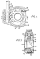
- FIGS. 4 and 5 illustrate an application of wormwheel gears produced as described above.
- a valve actuator 13 comprises a housing 13 having an upper casing section 14, and a lower casing section 15 secured together by fastening means such as the bolt 16.
- the housing may be cast in aluminium and preferably has multiple wall sections. Here double walls are shown with sections such as 14' and 14". The provision of multiple walling gives increased strength to the casing on account of the number of exposed wall surfaces produced in the casting process.
- the wormwheel gear 1 is located in the housing with its integral bearing 10 positioned in an opening in casing section 14. The opening in the casing 14 is sealed with a cap 17 which seals into opening 8 and cooperates with the splines 9.
- a bearing sleeve 18 has a portion 19 adapted to form a second bearing for the wormwheel gear 1.
- the second bearing is mounted in an opening in casing section 15.
- the bearing sleeve 18 also has an externally splined portion which is received in opening 8.
- the splines of portion 20 cooperate with splines 9 to prevent relative rotation of the sleeve 18 and the wormwheel gear.
- the sleeve 18 has a central axial opening 21 sized to receive the valve stem of the valve to be associated with the actuator.
- the interior of opening 21 may be provided with lugs or keyways or other means by which the valve stem may be mounted thereto.
- the bearing sleeve serves the dual purpose of providing the second bearing for the wormwheel and acting as an adaptor to the valve stem thus reducing the number of parts necessary to assemble a range of actuators for various different valves.
- the housing 13 also accommodates the worm 22 having a shaft 23 which extends outside the housing and may be provided with a suitable handle (not shown) for manually rotating it.
- a worm thread 24 is turned on the shaft 23 and engages with teeth 2 of wormwheel gear 1 such that rotation of the shaft about its axis causes rotation of the wormwheel gear 1 about its axis and thereby rotation of a valve stem (not shown) fitted in opening 21 in the bearing sleeve 18.
- the valve stem is connected to a butterfly valve vane which it is only necessary to rotate through 90° between its open and closed positions.
- the actuator is shown in a position wherein the valve would be in a closed position.
- a shoulder of the wormwheel gear abuts against a stop bolt 25 fixed in the housing.
- the stop bolt may be rotated to move it axially so as to make fine adjustments of the stop position of the wormwheel gear and thus the exact position of the butterfly vane in its valve seating in the closed position.
- the stop bolt is mounted between the two casing sections and passes through a nut 26 accommodated in cooperating recesses in the two sections 14 and 15. Thus it is not necessary for the bore in the aluminium casing in which the bolt is received to be threaded.
Priority Applications (1)
| Application Number | Priority Date | Filing Date | Title |
|---|---|---|---|
| AT81303734T ATE23214T1 (de) | 1980-08-29 | 1981-08-17 | Schneckenraeder. |
Applications Claiming Priority (2)
| Application Number | Priority Date | Filing Date | Title |
|---|---|---|---|
| GB8028068 | 1980-08-29 | ||
| GB8028068 | 1980-08-29 |
Publications (3)
| Publication Number | Publication Date |
|---|---|
| EP0047593A2 true EP0047593A2 (fr) | 1982-03-17 |
| EP0047593A3 EP0047593A3 (en) | 1983-01-26 |
| EP0047593B1 EP0047593B1 (fr) | 1986-10-29 |
Family
ID=10515740
Family Applications (1)
| Application Number | Title | Priority Date | Filing Date |
|---|---|---|---|
| EP81303734A Expired EP0047593B1 (fr) | 1980-08-29 | 1981-08-17 | Engrenage hélicoidal |
Country Status (5)
| Country | Link |
|---|---|
| US (1) | US4425815A (fr) |
| EP (1) | EP0047593B1 (fr) |
| AT (1) | ATE23214T1 (fr) |
| CA (1) | CA1167286A (fr) |
| DE (1) | DE3175532D1 (fr) |
Cited By (3)
| Publication number | Priority date | Publication date | Assignee | Title |
|---|---|---|---|---|
| EP0170989A1 (fr) * | 1984-08-08 | 1986-02-12 | Siemens Aktiengesellschaft | Dispositif de transmission à roue et vis sans fin |
| LT3239B (en) | 1993-03-12 | 1995-04-25 | Chemie Linz Gmbh | Hydrogenolytical reduction of peroxidated ozonolyse product |
| WO2011127919A1 (fr) * | 2010-04-14 | 2011-10-20 | Zf Lenksysteme Gmbh | Engrenage à vis sans fin |
Families Citing this family (8)
| Publication number | Priority date | Publication date | Assignee | Title |
|---|---|---|---|---|
| US4541296A (en) * | 1983-07-18 | 1985-09-17 | Ford Motor Company | Shock absorbing motor gear |
| GB8529811D0 (en) * | 1985-12-04 | 1986-01-15 | Stidworthy F M | Variable phase couplings |
| JPS643367A (en) * | 1987-06-25 | 1989-01-09 | Asmo Co Ltd | Adjusting structure for backlash of gear |
| US5664457A (en) * | 1992-06-05 | 1997-09-09 | Amir Nejati | Screw gear means and method for same |
| IT240393Y1 (it) * | 1996-01-19 | 2001-04-02 | Soldavini Teodoro | Dispositivo a quota elicoidale particolarmente studiato per gruppi ditrasmissione con riduzione del numero di giri, applicabile su |
| DE69728692T2 (de) * | 1996-05-03 | 2005-04-07 | Arvinmeritor Light Vehicle Systems-France | Getriebemotor, insbesondere zum Antrieb von Zubehörteilen in Kraftfahrzeugen |
| KR101393791B1 (ko) * | 2011-09-23 | 2014-05-13 | 현대자동차주식회사 | Bldc모터의 워엄휠 기어 |
| KR20150021658A (ko) * | 2013-08-21 | 2015-03-03 | 주식회사 만도 | 전동식 주차 브레이크 장치 |
Citations (9)
| Publication number | Priority date | Publication date | Assignee | Title |
|---|---|---|---|---|
| DE544445C (de) * | 1932-02-17 | Wuensch & Marcrander | Rad- oder Schneckengetriebe mit in der Radebene geteiltem Rade | |
| DE883380C (de) * | 1951-03-15 | 1953-07-16 | Siemens Ag | Schneckengetriebe |
| FR1131237A (fr) * | 1955-09-13 | 1957-02-19 | Procédé de fabrication de roues à dentures hélicoïdales ou de pièces analogues | |
| US2812668A (en) * | 1955-04-11 | 1957-11-12 | Danielson Mfg Company | Composite worm-helical gear construction |
| AT204850B (de) * | 1958-01-18 | 1959-08-10 | Kurt Krapfenbauer | Schneckenrad |
| GB1168213A (en) * | 1968-04-01 | 1969-10-22 | Claude Edward Kawchitch | Improvements in and relating to Torque Transmitting Elements |
| US3535948A (en) * | 1968-11-29 | 1970-10-27 | John Harold Winzeler | Worm gearing |
| CH544240A (de) * | 1971-07-23 | 1973-11-15 | Pfaff Haushaltmasch | Schnecken-Wechselgetriebe |
| GB2057627A (en) * | 1979-08-29 | 1981-04-01 | Bosch Gmbh Robert | Worm transmission mechanism for a periodically varying load |
-
1980
- 1980-10-10 US US06/196,022 patent/US4425815A/en not_active Expired - Lifetime
-
1981
- 1981-08-17 EP EP81303734A patent/EP0047593B1/fr not_active Expired
- 1981-08-17 DE DE8181303734T patent/DE3175532D1/de not_active Expired
- 1981-08-17 AT AT81303734T patent/ATE23214T1/de not_active IP Right Cessation
- 1981-08-28 CA CA000384761A patent/CA1167286A/fr not_active Expired
Patent Citations (9)
| Publication number | Priority date | Publication date | Assignee | Title |
|---|---|---|---|---|
| DE544445C (de) * | 1932-02-17 | Wuensch & Marcrander | Rad- oder Schneckengetriebe mit in der Radebene geteiltem Rade | |
| DE883380C (de) * | 1951-03-15 | 1953-07-16 | Siemens Ag | Schneckengetriebe |
| US2812668A (en) * | 1955-04-11 | 1957-11-12 | Danielson Mfg Company | Composite worm-helical gear construction |
| FR1131237A (fr) * | 1955-09-13 | 1957-02-19 | Procédé de fabrication de roues à dentures hélicoïdales ou de pièces analogues | |
| AT204850B (de) * | 1958-01-18 | 1959-08-10 | Kurt Krapfenbauer | Schneckenrad |
| GB1168213A (en) * | 1968-04-01 | 1969-10-22 | Claude Edward Kawchitch | Improvements in and relating to Torque Transmitting Elements |
| US3535948A (en) * | 1968-11-29 | 1970-10-27 | John Harold Winzeler | Worm gearing |
| CH544240A (de) * | 1971-07-23 | 1973-11-15 | Pfaff Haushaltmasch | Schnecken-Wechselgetriebe |
| GB2057627A (en) * | 1979-08-29 | 1981-04-01 | Bosch Gmbh Robert | Worm transmission mechanism for a periodically varying load |
Cited By (3)
| Publication number | Priority date | Publication date | Assignee | Title |
|---|---|---|---|---|
| EP0170989A1 (fr) * | 1984-08-08 | 1986-02-12 | Siemens Aktiengesellschaft | Dispositif de transmission à roue et vis sans fin |
| LT3239B (en) | 1993-03-12 | 1995-04-25 | Chemie Linz Gmbh | Hydrogenolytical reduction of peroxidated ozonolyse product |
| WO2011127919A1 (fr) * | 2010-04-14 | 2011-10-20 | Zf Lenksysteme Gmbh | Engrenage à vis sans fin |
Also Published As
| Publication number | Publication date |
|---|---|
| DE3175532D1 (de) | 1986-12-04 |
| EP0047593A3 (en) | 1983-01-26 |
| CA1167286A (fr) | 1984-05-15 |
| EP0047593B1 (fr) | 1986-10-29 |
| US4425815A (en) | 1984-01-17 |
| ATE23214T1 (de) | 1986-11-15 |
Similar Documents
| Publication | Publication Date | Title |
|---|---|---|
| EP0047593B1 (fr) | Engrenage hélicoidal | |
| US5018403A (en) | Globoid worm gear speed reduction apparatus | |
| US4825932A (en) | Method of making diecast inserts | |
| DE3711986A1 (de) | Kompressor in spiralbauweise und verfahren zu seiner herstellung | |
| US5320587A (en) | Differential case with ring gear attachment | |
| US7761995B2 (en) | Gear wheel with a multiple helical toothing, pressed in one part, and a method and device for manufacturing the same | |
| GB2185428A (en) | Method for the production of sintered bodies with internal passages, extrusion tool for carrying out the method and drilling tool | |
| US2126200A (en) | Method of making pump gears | |
| DE3938346C1 (fr) | ||
| EP1694985B1 (fr) | Denture de roulement et procede de fabrication | |
| DE102015217291A1 (de) | Nockenwellenversteller | |
| US5953957A (en) | Vehicle window drive system and method | |
| CN103717330A (zh) | 制造用于螺旋式机器的处理元件的方法和处理元件坯料 | |
| CN1564919A (zh) | 差速器和用于装配所述差速器的方法 | |
| EP0161421A2 (fr) | Pompe à huile à engrenages du type à roue mobile interne pour moteurs à combustion interne dans des véhicules automobiles | |
| US6368242B1 (en) | Axle shaft retainer system | |
| EP1001202B1 (fr) | Dispositif d'autonettoyage des sieges de soupapes des installations permettant d'obtenir de l'alumine | |
| US6041640A (en) | Spiral and hypoid tooth member and method and device for forming the same | |
| DE102014200818A1 (de) | Zweigeteilter Stator mit kaltverschweißtem Deckel | |
| EP0918177A1 (fr) | Differentiel à engrenages à axes parallèles | |
| JP2004161268A (ja) | 歯車機構を有するパワーステアリング | |
| US6067713A (en) | Method of manufacturing a rack and pinion steering gear | |
| EP0812640B1 (fr) | Roue d'engrenage | |
| CN107023477A (zh) | 螺杆泵 | |
| GB2170863A (en) | Rotary positive displacement pump or motor |
Legal Events
| Date | Code | Title | Description |
|---|---|---|---|
| PUAI | Public reference made under article 153(3) epc to a published international application that has entered the european phase |
Free format text: ORIGINAL CODE: 0009012 |
|
| AK | Designated contracting states |
Designated state(s): AT BE CH DE FR GB IT LU NL SE |
|
| PUAL | Search report despatched |
Free format text: ORIGINAL CODE: 0009013 |
|
| AK | Designated contracting states |
Designated state(s): AT BE CH DE FR GB IT LI LU NL SE |
|
| 17P | Request for examination filed |
Effective date: 19830725 |
|
| GRAA | (expected) grant |
Free format text: ORIGINAL CODE: 0009210 |
|
| AK | Designated contracting states |
Kind code of ref document: B1 Designated state(s): AT BE CH DE FR GB IT LI LU NL SE |
|
| ITF | It: translation for a ep patent filed |
Owner name: NOTARBARTOLO & GERVASI S.R.L. |
|
| PG25 | Lapsed in a contracting state [announced via postgrant information from national office to epo] |
Ref country code: BE Effective date: 19861029 Ref country code: AT Effective date: 19861029 |
|
| REF | Corresponds to: |
Ref document number: 23214 Country of ref document: AT Date of ref document: 19861115 Kind code of ref document: T |
|
| ET | Fr: translation filed | ||
| REF | Corresponds to: |
Ref document number: 3175532 Country of ref document: DE Date of ref document: 19861204 |
|
| PLBE | No opposition filed within time limit |
Free format text: ORIGINAL CODE: 0009261 |
|
| STAA | Information on the status of an ep patent application or granted ep patent |
Free format text: STATUS: NO OPPOSITION FILED WITHIN TIME LIMIT |
|
| PG25 | Lapsed in a contracting state [announced via postgrant information from national office to epo] |
Ref country code: LU Free format text: LAPSE BECAUSE OF NON-PAYMENT OF DUE FEES Effective date: 19870831 |
|
| 26N | No opposition filed | ||
| REG | Reference to a national code |
Ref country code: CH Ref legal event code: PUE Owner name: GBE OPPERMANN MASTERGEAR LIMITED Ref country code: CH Ref legal event code: PFA Free format text: AMRAF (NEWBURY) LIMITED |
|
| REG | Reference to a national code |
Ref country code: GB Ref legal event code: 732 |
|
| ITTA | It: last paid annual fee | ||
| ITPR | It: changes in ownership of a european patent |
Owner name: CESSIONE;GBE OPPERMAN MASTERGEAR LIMITED |
|
| NLT1 | Nl: modifications of names registered in virtue of documents presented to the patent office pursuant to art. 16 a, paragraph 1 |
Owner name: AMRAF (NEWBURY) LIMITED TE LONDEN, GROOT-BRITTANNI |
|
| NLS | Nl: assignments of ep-patents |
Owner name: GBE OPPERMAN MASTERGEAR LIMITED TE ANDOVER, GROOT- |
|
| PGFP | Annual fee paid to national office [announced via postgrant information from national office to epo] |
Ref country code: GB Payment date: 19930730 Year of fee payment: 13 |
|
| PGFP | Annual fee paid to national office [announced via postgrant information from national office to epo] |
Ref country code: FR Payment date: 19930805 Year of fee payment: 13 |
|
| PGFP | Annual fee paid to national office [announced via postgrant information from national office to epo] |
Ref country code: SE Payment date: 19930806 Year of fee payment: 13 |
|
| PGFP | Annual fee paid to national office [announced via postgrant information from national office to epo] |
Ref country code: DE Payment date: 19930812 Year of fee payment: 13 |
|
| PGFP | Annual fee paid to national office [announced via postgrant information from national office to epo] |
Ref country code: CH Payment date: 19930816 Year of fee payment: 13 |
|
| PGFP | Annual fee paid to national office [announced via postgrant information from national office to epo] |
Ref country code: NL Payment date: 19930831 Year of fee payment: 13 |
|
| PG25 | Lapsed in a contracting state [announced via postgrant information from national office to epo] |
Ref country code: GB Effective date: 19940817 |
|
| PG25 | Lapsed in a contracting state [announced via postgrant information from national office to epo] |
Ref country code: SE Effective date: 19940818 |
|
| PG25 | Lapsed in a contracting state [announced via postgrant information from national office to epo] |
Ref country code: LI Effective date: 19940831 Ref country code: CH Effective date: 19940831 |
|
| EAL | Se: european patent in force in sweden |
Ref document number: 81303734.8 |
|
| PG25 | Lapsed in a contracting state [announced via postgrant information from national office to epo] |
Ref country code: NL Effective date: 19950301 |
|
| NLV4 | Nl: lapsed or anulled due to non-payment of the annual fee | ||
| GBPC | Gb: european patent ceased through non-payment of renewal fee |
Effective date: 19940817 |
|
| PG25 | Lapsed in a contracting state [announced via postgrant information from national office to epo] |
Ref country code: FR Effective date: 19950428 |
|
| REG | Reference to a national code |
Ref country code: CH Ref legal event code: PL |
|
| PG25 | Lapsed in a contracting state [announced via postgrant information from national office to epo] |
Ref country code: DE Effective date: 19950503 |
|
| EUG | Se: european patent has lapsed |
Ref document number: 81303734.8 |
|
| REG | Reference to a national code |
Ref country code: FR Ref legal event code: ST |