EP0047211B1 - Verfahren zum Verändern der Umlaufbahn eines Satelliten, insbesondere zur Injektion in eine geostationäre Umlaufbahn, und für dieses Verfahren geeigneter Satellit - Google Patents
Verfahren zum Verändern der Umlaufbahn eines Satelliten, insbesondere zur Injektion in eine geostationäre Umlaufbahn, und für dieses Verfahren geeigneter Satellit Download PDFInfo
- Publication number
- EP0047211B1 EP0047211B1 EP81401354A EP81401354A EP0047211B1 EP 0047211 B1 EP0047211 B1 EP 0047211B1 EP 81401354 A EP81401354 A EP 81401354A EP 81401354 A EP81401354 A EP 81401354A EP 0047211 B1 EP0047211 B1 EP 0047211B1
- Authority
- EP
- European Patent Office
- Prior art keywords
- orbit
- vehicle
- satellite
- speed
- changing
- Prior art date
- Legal status (The legal status is an assumption and is not a legal conclusion. Google has not performed a legal analysis and makes no representation as to the accuracy of the status listed.)
- Expired
Links
- 238000000034 method Methods 0.000 title claims description 33
- 238000002347 injection Methods 0.000 title 1
- 239000007924 injection Substances 0.000 title 1
- 238000012546 transfer Methods 0.000 claims description 24
- 230000001133 acceleration Effects 0.000 claims description 17
- 230000008859 change Effects 0.000 claims description 10
- 230000007704 transition Effects 0.000 claims 1
- 210000004279 orbit Anatomy 0.000 description 53
- 230000008569 process Effects 0.000 description 7
- 230000005855 radiation Effects 0.000 description 6
- 230000008901 benefit Effects 0.000 description 3
- 230000000694 effects Effects 0.000 description 3
- 239000000446 fuel Substances 0.000 description 3
- 239000003380 propellant Substances 0.000 description 3
- 240000008042 Zea mays Species 0.000 description 2
- 238000002485 combustion reaction Methods 0.000 description 2
- 238000012937 correction Methods 0.000 description 2
- 238000001514 detection method Methods 0.000 description 2
- 238000010438 heat treatment Methods 0.000 description 2
- 230000009467 reduction Effects 0.000 description 2
- PEDCQBHIVMGVHV-UHFFFAOYSA-N Glycerine Chemical compound OCC(O)CO PEDCQBHIVMGVHV-UHFFFAOYSA-N 0.000 description 1
- 241000287107 Passer Species 0.000 description 1
- 230000009471 action Effects 0.000 description 1
- 230000004913 activation Effects 0.000 description 1
- 238000013459 approach Methods 0.000 description 1
- 230000003750 conditioning effect Effects 0.000 description 1
- 238000010276 construction Methods 0.000 description 1
- 238000007796 conventional method Methods 0.000 description 1
- 230000007423 decrease Effects 0.000 description 1
- 238000013461 design Methods 0.000 description 1
- 238000010586 diagram Methods 0.000 description 1
- 230000005611 electricity Effects 0.000 description 1
- 230000002349 favourable effect Effects 0.000 description 1
- 238000002513 implantation Methods 0.000 description 1
- 230000010354 integration Effects 0.000 description 1
- 239000007788 liquid Substances 0.000 description 1
- 239000000463 material Substances 0.000 description 1
- 230000008520 organization Effects 0.000 description 1
- 230000003071 parasitic effect Effects 0.000 description 1
- 230000004224 protection Effects 0.000 description 1
- 239000004449 solid propellant Substances 0.000 description 1
- 230000001629 suppression Effects 0.000 description 1
Images


Classifications
-
- B—PERFORMING OPERATIONS; TRANSPORTING
- B64—AIRCRAFT; AVIATION; COSMONAUTICS
- B64G—COSMONAUTICS; VEHICLES OR EQUIPMENT THEREFOR
- B64G1/00—Cosmonautic vehicles
- B64G1/22—Parts of, or equipment specially adapted for fitting in or to, cosmonautic vehicles
- B64G1/24—Guiding or controlling apparatus, e.g. for attitude control
- B64G1/242—Orbits and trajectories
- B64G1/2427—Transfer orbits
-
- B—PERFORMING OPERATIONS; TRANSPORTING
- B64—AIRCRAFT; AVIATION; COSMONAUTICS
- B64G—COSMONAUTICS; VEHICLES OR EQUIPMENT THEREFOR
- B64G1/00—Cosmonautic vehicles
- B64G1/22—Parts of, or equipment specially adapted for fitting in or to, cosmonautic vehicles
- B64G1/24—Guiding or controlling apparatus, e.g. for attitude control
- B64G1/26—Guiding or controlling apparatus, e.g. for attitude control using jets
Definitions
- the subject of the invention is both a method of changing the orbit of a satellite and in particular the passage from a highly elliptical orbit to a circular orbit possibly geosynchronous and of different inclination, as well as a device for implementing said method .
- a multi-stage rocket places it on an elliptical orbit known as of transfer whose perigee is in the vicinity of the altitude of culmination of the rocket is a few hundred kilometers whose apogee is approximately at the subsequent altitude of revolution and whose inclination is generally different from that of the final orbit, because it depends on the latitude of the launch point.
- the change of orbit is done by increasing the speed of the satellite in the immediate vicinity of the apogee of the transfer orbit, increase obtained thanks to the thrust of a so-called apogee motor which in a very short time produces a significant amount of movement.
- This maneuver is unique; it is however supplemented by small corrections provided by the auxiliary nozzles.
- the first method known as Hohmann transfer is all the more effective when the speed increase is brief, which has led to the use of solid propellant engines whose combustion time is a few seconds; it has the disadvantage of creating a significant acceleration which can be dimensioning for the mechanical structures, and of causing significant heating which requires particular protections.
- This known method requires a specific propellant to put into orbit and leads to accelerations which may still be incompatible with the mechanical strength of certain structural elements, in particular appendages such as large antennas, solar panels, masts.
- the other method mentioned above uses motors with magneto-hydrodynamic effect called electric propellers and generating very low accelerations; the travel time of the spiral orbit is then very important, several months, which leads to a loss of time and a travel time in the zones of intense radiation surrounding the earth known as the Van Allen belts which is large and causes damage to the vehicle, in particular to the solar cells of the electricity generators.
- a third orbit change process is also known, according in particular to patent DE-A 2850920, according to which, starting from a low circular orbit, the vehicle is made to describe a succession of intermediate elliptical orbit tangent to this orbit low and whose apogees rise gradually towards the high orbit; for this the vehicle is subjected to weak accelerations at the perigee of each intermediate orbit; when the altitude of the high orbit is reached the vehicle is subjected, at the peak of the last intermediate orbit, to a single acceleration which places it in the desired orbit.
- the vehicle is deployed in operational configuration during the course of the low orbit and the intermediate accelerations are sufficiently low to be compatible with the mechanical behavior of the vehicle in this configuration.
- the propulsion of the vehicle however requires the specific means necessary to obtain the significant final acceleration.
- the subject of the present invention is a method for changing orbit and a device for implementing said method using not specific thrusters, but those essential for controlling orbit and attitude during the operational life of the satellite.
- any geostationary satellite must have thrusters capable of maintaining it at fixed longitude, which requires providing it with accelerations along the tangent to the orbit in both possible directions, that is to say in the East-West and West-East directions.
- tilt correction thrusters the thrust of which is directed along the North-South line
- attitude control thrusters which provide torques around the three axes of the vehicle.
- thrusters having weak thrusts, it is not possible to carry out a single Hohmann transfer, but on the other hand, it is possible to actuate them when the satellite is fully deployed (antennas, solar panels, masts, etc.) without damage it, which benefits the invention.
- the method according to the invention consists in aiming with the launcher for a transfer orbit whose apogee is close to the desired final value and in providing in the vicinity of successive climaxes increments of speed, direction and modulus perfectly defined so to raise the altitude of the Périgés. After a few revolutions, the final orbit is reached. Certainly, the sum of the speed increments is slightly greater than a single increment as required by the single Hohmann transfer.
- FIG. 1 which diagrams the various Hohmann maneuvers
- the launch phase 1 during which the rocket places the satellite in a low circular orbit
- the transfer phase 2 during which the satellite is injected, thanks to an increase speed at perigee, on an elliptical orbit whose apogee corresponds to the final altitude sought and where a second increase in speed 3 injects the satellite into the final circular orbit 4.
- the parts referenced 5 and 6 schematize the radiation zones intense known as Van Allen belts.
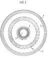
- FIG. 2 which shows an ascent using a spiral trajectory thanks to a very small but continuous increase in speed
- the transfer phase 2 which is constituted by the spiral trajectory properly said.
- In 3 takes place the last maneuver allowing the satellite to be injected into the final circular orbit 4.
- In 5 and 6 are shown the Van Allen belts.
- the satellite After the launch phase 1, the satellite is placed on a first elliptical half-orbit 2 towards the apex of which a speed increment 3A is delivered.
- the satellite then describes a second elliptical orbit 4A having a significantly higher perigee and a very slightly higher apogee.
- a new speed increment 3B is delivered to the new apogee, which places the vehicle on a new elliptical orbit 4B having a perigee markedly higher and an apogee slightly higher than that of the previous orbit.
- Van Allen belts are shown diagrammatically in 5 and 6.
- Each of the indicated maneuvers can be performed outside the orbital plane so as to modify the inclination gradually until reaching the final inclination.
- successive orbital change maneuvers are designed so that the last maneuver positions the vehicle at its end point.
- the maneuvers are designed to bring the vehicle to the final anomaly at the same time, the last maneuver consists in canceling the speed at this point.
- the method according to the invention does not use specific propellants, as in the previous methods, but those essential for controlling orbit and attitude during the operational life of the satellite.
- the movement of a terrestrial satellite is governed by the laws of movement under the action of the Newtonian attraction of the earth alone, one of the main characteristics of which is that the length of the major axis depends on the total energy. supplied to the vehicle; this is why the most effective way to change this semi-major axis and thus to raise the altitude of the satellite is to increase the value of the speed which leads to the Hohmann maneuvers as shown diagrammatically in Figure 1 where the rocket places the satellite in a low circular orbit then injects it thanks to an increase in speed at the perigee on an elliptical orbit whose apogee corresponds to the final altitude sought, and where a second increase in speed injects it on the final circular orbit.
- the speed increase must be 1750 m / s approximately at the peak.
- the judicious choice of the succession of increments may take account of other criteria. For example, it is possible to minimize the evolution time in given altitude ranges, chosen as being able to symbolize the zones of intense radiation known under the name of Van Allen belts; the longitude of the final position of the satellite can also be optimized at the same time so as to eliminate the so-called drift phase in conventional orbiting. This allows a significant saving of time and fuel.
- the velocities listed above must be given the same orientation outside the plane of the ellipse which would be necessary in a Hohmann transfer.
- the satellite can be put into an almost definitive configuration, that is to say say that the solar panels, the antennas, the masts, ... will be developed and the attitude towards the sun will be acquired. From then on, the electrical supplies and the thermal conditioning will be in operational configuration.
- the acquisition of the ground by the terrestrial sensors will be carried out by conventional means, that is to say pre-acquisition starting from precalculated data and by controlling the vehicle in speed according to the indications of the gyrometers, then fine acquisition with terrestrial sensors.
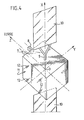
- the thrust in the direction normal to the east face 11 of the satellite will be obtained by activation of four nozzles 12 for orbit and attitude control located on this face.
- these four thrusts will be controlled and modulated as a function of the attitude or angular velocity information during combustion.
Claims (5)
Applications Claiming Priority (2)
| Application Number | Priority Date | Filing Date | Title |
|---|---|---|---|
| FR8018918 | 1980-09-02 | ||
| FR8018918A FR2491867A1 (fr) | 1980-09-02 | 1980-09-02 | Procede de changement d'orbite d'un satellite, notamment d'injection en orbite geostationnaire et satellite mettant en oeuvre ledit procede |
Publications (2)
| Publication Number | Publication Date |
|---|---|
| EP0047211A1 EP0047211A1 (de) | 1982-03-10 |
| EP0047211B1 true EP0047211B1 (de) | 1985-02-06 |
Family
ID=9245564
Family Applications (1)
| Application Number | Title | Priority Date | Filing Date |
|---|---|---|---|
| EP81401354A Expired EP0047211B1 (de) | 1980-09-02 | 1981-08-27 | Verfahren zum Verändern der Umlaufbahn eines Satelliten, insbesondere zur Injektion in eine geostationäre Umlaufbahn, und für dieses Verfahren geeigneter Satellit |
Country Status (4)
| Country | Link |
|---|---|
| EP (1) | EP0047211B1 (de) |
| JP (1) | JPS5777298A (de) |
| DE (1) | DE3168786D1 (de) |
| FR (1) | FR2491867A1 (de) |
Families Citing this family (7)
| Publication number | Priority date | Publication date | Assignee | Title |
|---|---|---|---|---|
| US5595360A (en) * | 1994-03-25 | 1997-01-21 | Hughes Aircraft Company | Optimal transfer orbit trajectory using electric propulsion |
| FR2747102B1 (fr) * | 1996-04-05 | 1998-06-26 | Europ Propulsion | Procede et systeme de mise en orbite d'un vehicule spatial avec des propulseurs a forte impulsion specifique |
| US6341749B1 (en) * | 1998-09-25 | 2002-01-29 | Hughes Electronics Corporation | Method of simultaneously reducing inclination and eccentricity for geostationary orbit transfer |
| US6672542B2 (en) * | 2002-06-03 | 2004-01-06 | The Aerospace Corporation | Method and system for controlling the eccentricity of a near-circular orbit |
| CN114348298B (zh) * | 2021-11-30 | 2023-05-16 | 中国西安卫星测控中心 | 适用于地球同步卫星混合推进入轨的联合优化方法 |
| CN115535307B (zh) * | 2022-12-01 | 2023-03-03 | 银河航天(北京)通信技术有限公司 | 卫星轨道转移策略确定方法以及装置 |
| CN116461721A (zh) * | 2023-05-15 | 2023-07-21 | 中国科学院微小卫星创新研究院 | 一种应用于卫星辅助入轨的模块化电磁动力背包及卫星入轨方法 |
Family Cites Families (1)
| Publication number | Priority date | Publication date | Assignee | Title |
|---|---|---|---|---|
| FR2569162A1 (fr) * | 1977-11-25 | 1986-02-21 | Ford Aerospace & Communication | Procede de mise sur orbite de satellites et de vaisseaux spatiaux |
-
1980
- 1980-09-02 FR FR8018918A patent/FR2491867A1/fr active Granted
-
1981
- 1981-08-27 EP EP81401354A patent/EP0047211B1/de not_active Expired
- 1981-08-27 DE DE8181401354T patent/DE3168786D1/de not_active Expired
- 1981-08-31 JP JP56136943A patent/JPS5777298A/ja active Granted
Non-Patent Citations (1)
| Title |
|---|
| ASTRONAUTICA ACTA, vol. 12, 1966 (US) J.E. McINTYRE et al.: "Linearized Treatment of the Optimal Transfer of a Thrust-Limited Vehicle Between Coplanar Circular Orbits", pages 224-234 * |
Also Published As
| Publication number | Publication date |
|---|---|
| JPH0215440B2 (de) | 1990-04-12 |
| FR2491867A1 (fr) | 1982-04-16 |
| EP0047211A1 (de) | 1982-03-10 |
| FR2491867B1 (de) | 1982-11-12 |
| DE3168786D1 (en) | 1985-03-21 |
| JPS5777298A (en) | 1982-05-14 |
Similar Documents
| Publication | Publication Date | Title |
|---|---|---|
| EP0799768B1 (de) | System und Verfahren um mit Triebwerken mit hohen spezifischen Impulsen versehen ein Raumfahrzeug in eine Umlaufbahn zu bringen | |
| EP0519038B1 (de) | Verfahren zur steuerung des nickwinkels eines satelliten mittels sonnenwinddruck und satellit zur durchführung desselben | |
| EP0854082B1 (de) | Verfahren um Satelliten in nicht-koplanaren Umlaufbahnen mit Hilfe der Mondschwerkraft zu bringen | |
| EP2810875B1 (de) | Bimodulares Antriebssystem für Orbit- und Fluglageregelung eines Satelliten | |
| EP2810876B1 (de) | Viermodulares Antriebssystem für Orbit- und Fluglageregelung eines Satelliten | |
| EP0854083B1 (de) | Verfahren um Satelliten in nicht-koplanare Umlaufbahnen unter Verwendung von sehr excentrischen Umlaufbahnen und atmosphärischem Strömungswiderstand gleichzeitig zu bringen | |
| EP0394897B1 (de) | Verfahren zur Positionierung eines geostationären Telekommunikationssatelliten | |
| EP0435708B1 (de) | Verfahren zur Steuerung der Neigung eines Satelliten bezüglich der Roll- und der Gierachse | |
| EP2690020B1 (de) | Verfahren zur Reduzierung des Drehimpulses und zur Fluglageregelung eines Raumfahrzeugs | |
| EP2878539B1 (de) | Düsensystem und verfahren zur kontrolle der umlaufbahn und des verhaltens für geostationären satelliten | |
| EP3074309B1 (de) | Verfahren und vorrichtung zur steuerung einer sonnenlichtaufnahmephase eines raumfahrzeuges | |
| FR2775251A1 (fr) | Configuration du montage du propulseur a usage multiple | |
| FR2990193A1 (fr) | Systeme de propulsion pour controle d'orbite et controle d'attitude de satellite | |
| EP3201091B1 (de) | Verfahren zur überwachung der lage eines satelliten in überlebensmodus, angepasste satellit und verfahren zur fernsteuerung solch eines satelliten | |
| EP4153490B1 (de) | Verfahren zur optimierung des orbitalen transfers eines elektrisch angetriebenen raumfahrzeugs und das verfahren verwendender satellit | |
| FR2945515A1 (fr) | Systeme comportant une sonde spatiale mere formant vehicule spatial porteur et une pluralite de sondes spatiales filles | |
| EP0047211B1 (de) | Verfahren zum Verändern der Umlaufbahn eines Satelliten, insbesondere zur Injektion in eine geostationäre Umlaufbahn, und für dieses Verfahren geeigneter Satellit | |
| FR2569162A1 (fr) | Procede de mise sur orbite de satellites et de vaisseaux spatiaux | |
| EP2727844B1 (de) | Optimierte Antriebsvorrichtung für die Kontrolle der Umlaufbahn und der Höhe von Satelliten | |
| FR2636040A1 (fr) | Vehicule spatial pour mission en microgravite et procede d'experimentation utilisant un tel vehicule | |
| Kinoshita et al. | Outline of the experimental lunar lander in SELENE project |
Legal Events
| Date | Code | Title | Description |
|---|---|---|---|
| PUAI | Public reference made under article 153(3) epc to a published international application that has entered the european phase |
Free format text: ORIGINAL CODE: 0009012 |
|
| AK | Designated contracting states |
Designated state(s): CH DE GB IT NL SE |
|
| 17P | Request for examination filed |
Effective date: 19820513 |
|
| ITF | It: translation for a ep patent filed |
Owner name: BARZANO' E ZANARDO ROMA S.P.A. |
|
| GRAA | (expected) grant |
Free format text: ORIGINAL CODE: 0009210 |
|
| AK | Designated contracting states |
Designated state(s): CH DE GB IT LI NL SE |
|
| REF | Corresponds to: |
Ref document number: 3168786 Country of ref document: DE Date of ref document: 19850321 |
|
| PLBI | Opposition filed |
Free format text: ORIGINAL CODE: 0009260 |
|
| 26 | Opposition filed |
Opponent name: MESSERSCHMIDT - BOELKOW - BLOHM GMBH, OTTOBRUNN Effective date: 19851106 |
|
| NLR1 | Nl: opposition has been filed with the epo |
Opponent name: MESSERSCHMIDT-BOELKOW-BLOHM GMBH, OTTOBRUNN |
|
| PGFP | Annual fee paid to national office [announced via postgrant information from national office to epo] |
Ref country code: CH Payment date: 19900808 Year of fee payment: 10 |
|
| PGFP | Annual fee paid to national office [announced via postgrant information from national office to epo] |
Ref country code: GB Payment date: 19900816 Year of fee payment: 10 |
|
| PGFP | Annual fee paid to national office [announced via postgrant information from national office to epo] |
Ref country code: SE Payment date: 19900821 Year of fee payment: 10 |
|
| PGFP | Annual fee paid to national office [announced via postgrant information from national office to epo] |
Ref country code: NL Payment date: 19900831 Year of fee payment: 10 |
|
| PGFP | Annual fee paid to national office [announced via postgrant information from national office to epo] |
Ref country code: DE Payment date: 19901011 Year of fee payment: 10 |
|
| RDAG | Patent revoked |
Free format text: ORIGINAL CODE: 0009271 |
|
| STAA | Information on the status of an ep patent application or granted ep patent |
Free format text: STATUS: PATENT REVOKED |
|
| REG | Reference to a national code |
Ref country code: CH Ref legal event code: PL |
|
| 27W | Patent revoked |
Effective date: 19901108 |
|
| GBPR | Gb: patent revoked under art. 102 of the ep convention designating the uk as contracting state | ||
| NLR2 | Nl: decision of opposition | ||
| ITTA | It: last paid annual fee | ||
| EUG | Se: european patent has lapsed |
Ref document number: 81401354.6 Effective date: 19910306 |
|
| APAH | Appeal reference modified |
Free format text: ORIGINAL CODE: EPIDOSCREFNO |