EP0047132A2 - Method of and apparatus for transferring semiconductor wafers between carrier members - Google Patents
Method of and apparatus for transferring semiconductor wafers between carrier members Download PDFInfo
- Publication number
- EP0047132A2 EP0047132A2 EP81303904A EP81303904A EP0047132A2 EP 0047132 A2 EP0047132 A2 EP 0047132A2 EP 81303904 A EP81303904 A EP 81303904A EP 81303904 A EP81303904 A EP 81303904A EP 0047132 A2 EP0047132 A2 EP 0047132A2
- Authority
- EP
- European Patent Office
- Prior art keywords
- housing
- articles
- baffle
- carrier
- carrier member
- Prior art date
- Legal status (The legal status is an assumption and is not a legal conclusion. Google has not performed a legal analysis and makes no representation as to the accuracy of the status listed.)
- Granted
Links
Images


Classifications
-
- H—ELECTRICITY
- H01—ELECTRIC ELEMENTS
- H01L—SEMICONDUCTOR DEVICES NOT COVERED BY CLASS H10
- H01L21/00—Processes or apparatus adapted for the manufacture or treatment of semiconductor or solid state devices or of parts thereof
- H01L21/67—Apparatus specially adapted for handling semiconductor or electric solid state devices during manufacture or treatment thereof; Apparatus specially adapted for handling wafers during manufacture or treatment of semiconductor or electric solid state devices or components ; Apparatus not specifically provided for elsewhere
- H01L21/677—Apparatus specially adapted for handling semiconductor or electric solid state devices during manufacture or treatment thereof; Apparatus specially adapted for handling wafers during manufacture or treatment of semiconductor or electric solid state devices or components ; Apparatus not specifically provided for elsewhere for conveying, e.g. between different workstations
- H01L21/67763—Apparatus specially adapted for handling semiconductor or electric solid state devices during manufacture or treatment thereof; Apparatus specially adapted for handling wafers during manufacture or treatment of semiconductor or electric solid state devices or components ; Apparatus not specifically provided for elsewhere for conveying, e.g. between different workstations the wafers being stored in a carrier, involving loading and unloading
- H01L21/67778—Apparatus specially adapted for handling semiconductor or electric solid state devices during manufacture or treatment thereof; Apparatus specially adapted for handling wafers during manufacture or treatment of semiconductor or electric solid state devices or components ; Apparatus not specifically provided for elsewhere for conveying, e.g. between different workstations the wafers being stored in a carrier, involving loading and unloading involving loading and unloading of wafers
- H01L21/67781—Batch transfer of wafers
-
- Y—GENERAL TAGGING OF NEW TECHNOLOGICAL DEVELOPMENTS; GENERAL TAGGING OF CROSS-SECTIONAL TECHNOLOGIES SPANNING OVER SEVERAL SECTIONS OF THE IPC; TECHNICAL SUBJECTS COVERED BY FORMER USPC CROSS-REFERENCE ART COLLECTIONS [XRACs] AND DIGESTS
- Y10—TECHNICAL SUBJECTS COVERED BY FORMER USPC
- Y10S—TECHNICAL SUBJECTS COVERED BY FORMER USPC CROSS-REFERENCE ART COLLECTIONS [XRACs] AND DIGESTS
- Y10S414/00—Material or article handling
- Y10S414/135—Associated with semiconductor wafer handling
- Y10S414/137—Associated with semiconductor wafer handling including means for charging or discharging wafer cassette
- Y10S414/138—Wafers positioned vertically within cassette
-
- Y—GENERAL TAGGING OF NEW TECHNOLOGICAL DEVELOPMENTS; GENERAL TAGGING OF CROSS-SECTIONAL TECHNOLOGIES SPANNING OVER SEVERAL SECTIONS OF THE IPC; TECHNICAL SUBJECTS COVERED BY FORMER USPC CROSS-REFERENCE ART COLLECTIONS [XRACs] AND DIGESTS
- Y10—TECHNICAL SUBJECTS COVERED BY FORMER USPC
- Y10S—TECHNICAL SUBJECTS COVERED BY FORMER USPC CROSS-REFERENCE ART COLLECTIONS [XRACs] AND DIGESTS
- Y10S414/00—Material or article handling
- Y10S414/135—Associated with semiconductor wafer handling
- Y10S414/14—Wafer cassette transporting
Definitions
- the present invention relates to a method of and apparatus for transferring articles, particularly thin articles of a disc- like nature, from one carrier member to another.
- the invention is particularly suitable for transferring unprocessed semiconductor wafers from a first carrier member (hereinafter also referred to simply as a "carrier”) to a second carrier member (hereinafter also referred to as a "magazine") so that they may be processed in the magazine, e.g. in a furnace.
- the magazine therefore must be resistant to processing temperatures and in this particular art would generally be made from fused silica, whereas the carrier may be made from any suitable material, generally a suitable plastics material.
- the apparatus may also be used for re-transferring processed wafers back to the carrier. In the course of such transfer operations handling of the delicate wafers must be kept to a minimum to prevent damage and contamination which would lead to rejection of the very expensive articles.
- the invention consists in a method of transferring articles between first and second carrier members, wherein articles in a first carrier member are caused to pass nearly, but not quite wholly, into a second carrier member whereafter the carrier members are subjected to a displacement and said articles are allowed to pass wholly into said carrier member.
- the carrier members are conveniently located in a housing and the displacement is effected by inverting said housing, advantageously by a rotary movement, the final movement of the articles being under the control of gravity.
- the invention also provides transfer apparatus which comprises a displaceable housing for containing a baffle means adapted to receive articles from a first carrier member placed in the housing and pass such articles into a second carrier member along a distance less than that represented by a final desired position, the full distance to said final desired position being travelled by said articles only after displacement of said housing.
- the displacement referred to is an inversion, the housing, for this purpose, being rotatably mounted and the further distance travelled by the articles after rotational displacement of the housing being under the influence of gravity and of very small dimensions which is defined herein as being of the order of 2 mm.
- Locking means are preferably provided to prevent the housing being inadvertantly displaced before the transfer of the articles.
- the housing may be mounted on a horizontal spindle for movement through 180 0 in either direction.
- the housing may have frontal and/or lateral loading and unloading ports to enable the carrier members to be loaded into and unloaded from the housing.
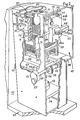
- FIG. 1 there is shown a first embodiment of a transfer mechanism incorporating the basic features of the invention and comprising a housing 1 rotatable about a horizontal axis in relation to a stand 2.
- the housing has a spindle projecting axially from its rear end to engage in anti-friction bearings in an aperture in the vertical portion 3 of the stand 2 (the spindle and aperture are not shown).
- the front end of the upper part of the housing. is open, to gain access to a shuttle baffle 4, constituting the baffle means hereinabove referred to, and being in two parts 4a and 4b, the upper part 4b being slidable relative to the lower part 4a.
- the whole shuttle baffle unit is carried by and longitudinally slidable on, a pair of rails 5 secured to the inside of housing 1, the sides of the shuttle baffle being grooved at 6 for this purpose.
- a flange To the frontal end of the shuttle baffle 4a is secured a flange through a threaded aperture in which passes a threaded operating plunger 8, whose front end is secured to a hand wheel 9. Rotation of the hand wheel 9 effects a translational movement of the upper part 4b of the shuttle baffle, the rear end of plunger 8 bearing on the front end of part 4b. The translational movement of part 4b is stopped by a stop disc or plate secured to the rear face of part 4a (not shown).
- the rear end of plunger 8 may be coupled to the front end of part 4b in such a manner that the plunger 8 can rotate, or the part 4b may be spring-loaded so that in any event rotation of wheel 9 in one direction will affect a front to rear translation of the part 4b and a rotation of wheel 9 in the opposite direction will affect a rear to front translation of the part 4b.
- housing 1 In the lower part of housing 1 there is provided a platform 10 to which is secured a guide boss 11 through which passes a lifting pillar 12 to the upper end of which is secured a support member 13.
- a rack (not shown) is formed in or attached to the front longitudinal circumference of pillar 12, which rack is engaged by a pinion 14 secured to a shaft 15 which passes through the walls of the lower part of housing 1, as shown.
- a handle 16 To one end of shaft 15 is secured a handle 16, conveniently via a disc 17, outside the housing whereby rotation of handle 16 rotates shaft 15 to cause a vertical movement of pillar 12 and support member 13.
- the spindle 15 also carries a cam disc 18 inside the casing and a locking rod 19 passes through the rear wall of housing 1 and is supported at its front end in a bracket 20 secured to the inner wall of the housing.
- the locking rod 19 passes rearwardly into an apertured boss 5a in the vertical part 3 of stand 2 so as to secure the housing 1 against rotation.
- the front end of rod 19 is spring-urged against the periphery of cam disc 18 so that when a cut-out 21 in cam disc 18 meets the front end of locking rod 19, the latter is urged forwardly to free the rear end of rod 19 from the apertured boss 3a in vertical part 3 to allow rotation of housing 1 about its horizontal mounting spindle.
- the disc 17 carries a spring-loaded plunger, (not shown) passing therethrough into an aperture in the adjacent side wall of housing 1, the exterior end of this plunger bearing an operating head 22. It will be clear that at a suitable angular position of handle 16, this plunger will automatically enter the aperture and lock the shaft 15 against further rotation until the plunger is withdrawn by hand to release the shaft 15.
- This construction enables transfer of articles from a first carrier member i.e. carrier 23, to a second carrier member i.e. a magazine 24 and vice versa
- the carrier 23 being a cage'open at top and bottom and its side walls being grooved so as to receive a number of articles e.g. discs 26, such as semiconductor wafers, the spacing between these side walls being such as to retain the articles 26 at diametrically opposite points so that they depend towards the open bottom of the cage.
- the interior walls of parts 4a and 4b of shuttle baffle 4 are also grooved as 27 and 28 to allow passage of the articles 26 as will be explained.
- the grooved portions take the form of separate insert bodies screwed or otherwise secured to the respective baffle parts so that they may be removed for easy cleaning.
- any material found suitable may be used to make the shuttle baffle, we have found that polypropylene is one suitable material for the body thereof and the groove-inserts may be of polytetrafluorethylene.
- the magazine 24 is made from fused silica and the stand and housing may be made from any rigid plastics material as are the other parts.
- the pinion and its associated rack may be made from nylon.
- the magazine 24 is arranged to be clamped to the upper part of shuttle baffle 4 by means of locking arms 29, two on each side of the baffle 4, which are secured thereto by screws or the like so that they may pivot.
- the limbs of the arms 29 are pinned to operating rods 31 so that longitudinal movement of each rod causes the working arms 29 to pivot on their screws.
- the one ends of each operating rod 31 may be secured together by a transverse tie provided with an operating handle whereby movement of the latter may move both rods 31 and therewith all four arms 29 simultaneously, but this simple mechanical expedient will be apparent to those skilled in the art and has therefore not been shown.
- the magazine 24 is constituted by two longitudinal struts 32 and 33 joined together by transverse struts 34 and 35 and two further longitudinal struts 36 and 37 secured to the ends of the struts 34 and 35 which'latter are in the form of tubes, open at their respective ends whereby the holder can be loaded unto and removed from the shuttle baffle 4 by a forked hand tool e.g. as shown in Figure 9, comprising a handle device having two spaced tines arranged to be passed into the tube ends.
- the interior surface of the struts 32, 33, 36 and 37 are transversely grooved, each set of four grooves being intended to accommodate one article such as a disc 26, but the spacing between the grooves in these struts as well as the grooves 28 in part 4b of the shuttle 4, -is half that of the grooves 25 in carrier 23 and grooves 27 in part 4a of baffle 4, so that the magazine 24 is capable of holding twice as many articles as the carrier 23.
- this pertains only to the embodiment shown and the holding capabilities of the carrier members may be varied as desired.
- An empty magazine 24 is placed upside down, as shown, on the upper face of baffle part 4b and is locked in position by locking arms 29 whilst the baffle 4 is outside the apparatus.
- the baffle is then slid into the upper part of housing 1 on slide rails 5.
- a carrier 23, loaded with articles 26 is inserted into housing 1 beneath the baffle 4.
- the operating head 22 is then pulled out under spring pressure, to release its plunger from the aperture in the wall of the lower part of housing 1.
- the handle 16 can then be operated to lift pillar 12 and support member 13 to cause the articles 26 to pass into the baffle 4 occupying alternate grooves in part 4b, until the plunger on head 22 again locks handle 16 at which time it is arranged that the articles 26 do not fully bottom in the grooves in longitudinal struts 32, 33 i.e. they are not fully "home” into the magazine 24, being short by, say, 2 mm.
- the locking rod 19 will also be freed from part 3 of stand 2 whereupon the housing 1 is rotated clockwise through 180 0 until it reaches a stop (not shown), thus inverting the carrier members so that they exchange positions.
- the shuttle baffle 4 is then indexed by rotating hand wheel 9 until it meets and end stop thereby achieving the closure of grooves occupied by the first load of articles 26, and opening each unoccupied slot in magazine 24 and part 4b of baffle 4, ready to receive the second load of articles 26.
- the articles 26 thus enter the magazine 24 with minimum force by gravity but they will have suffered no damage due to the fact that the dropping distance is so small.
- the housing 1 is then rotated anti-clockwise through 180 0 and returned to its initial position.
- the operating head 22 is then retracted and handle'16 is moved back to its start position, thereby returning support member 13.
- the empty carrier 23 is removed and replaced by a second loaded one and the operation is repeated, the articles from this second carrier being loaded into the grooves between those first loaded.
- the magazine 24 contains the contents of both carriers 23, the second "load” also having been gently dropped into the "home” position on the next rotation of the housing 1.
- the shuttle baffle 4 can then be removed from the apparatus and magazine 24 lifted off after releasing the locking arms 29.
- Unloading a magazine 24 and distributing its load of articles 26 into two carriers 23, is carried out by a reversal of the above procedure.
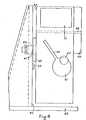
- the transfer mechanism therein shown is more sophisticated than that shown in Figure 1 and comprises a housing 40 rotatable about a horizontal axis 41 in the vertical wall 42 of a stand 43.
- This horizontal axis takes the form of a shaft projecting axially from the rear end 44 of the housing, passing through a boss 45, to engage in anti-friction bearings 46 in an aperture in the vertical wall 42 of the stand 43 ( Figure 4).
- the frontal end of the upper part of the housing 40 is open at 47, to gain access to a shuttle baffle 48 that is in two vertically-separated parts 48a and 48b, the upper part 48b being slidable relative to the lower part 48a.
- the whole shuttle baffle unit is carried by and longitudinally slidable on, a pair of rails 49 secured to the inside of housing 40, the sides of the shuttle baffle being grooved at 50 for this purpose.
- the housing also has a lateral loading and unloading port 51.
- a flange 52 To the frontal end of the shuttle baffle 48a is secured a flange 52 through a threaded aperture in which passes a threaded operating shaft, whose front end is secured to a hand lever 53, movement of which effects a translational indexing movement of the upper part 48b of the shuttle baffle with respect to the lower part 48a but the two parts cannot be vertically separated due to a dovetail-grooved connector 48c between them, the rear end of the shaft secured to lever 53 bearing on the front end of part 48b.
- the translational movement of part 48b is stopped by a stop disc or plate secured to the rear face of part 48a (not shown).
- the rear end of said shaft may be coupled to the front end of part 48b in such a manner that the shaft can rotate, or the part 48b may be spring-loaded so that in any event rotation of lever 53 in one direction will affect a front to rear translation of the part 48b and a movement of lever 53 in the opposite direction will affect a rear to front translation of the part 48b.
- a platform 54 to which is secured a guide boss 55 through which passes a lifting pillar 56 to the upper end of which are secured lifting bars 57.
- a rack (not shown) is formed in or attached to the front longitudinal circumference of pillar 56, which rack is engaged by a pinion 58 secured to a shaft 59 which passes through the walls of the lower part of housing 40 as shown.
- a handle 60 To one end of shaft 59 is secured a handle 60, conveniently via a disc 61, outside.the housing whereby rotation of handle 60 rotates shaft 59 to cause a vertical movement of pillar 56 and lifting bars 57.
- the spindle 59 also carries a cam disc 62 inside the casing and a locking rod 63 passes through the rear wall of housing 40 and is supported at its front end in a bracket 64 secured to the inner wall of the housing.
- the locking rod 63 passes rearwardly into an apertured boss 65 in vertical wall 42 of stand 43 so as to secure the housing 40 against rotation.
- the front end of rod 63 is spring-urged against the periphery of cam disc 62 so that when a cut-out 66 in cam disc 62 meets the front end of locking rod 63, the latter is urged forwardly to free the rear end of rod 63 from the apertured boss 65 in vertical wall 42 to allow rotation of housing 40 about its horizontal mounting spindle 41.
- the disc 61 carries a spring-loaded plunger, (not shown) passing therethrough into an aperture in the adjacent side wall of housing 40 the exterior end of this plunger bearing a locking knob 67. It will be clear that at a suitable angular position of handle 60, this plunger will automatically enter the aperture and lock the shaft 59 against further rotation until the plunger is withdrawn by hand to. release the shaft 59.
- This construction enables transfer of articles from a carrier 68 to a magazine 69 and vice versa, the carrier 68, being a cage open at top and bottom (see particularly Figure 5), and its side walls being grooved at 70 so as to receive a number of articles e.g. discs 71, the spacing between these side walls being such as to retain the articles 71 at diametrically opposite points so that they depend towards the open bottom of the cage.
- the interior walls of parts 48a and 48b of shuttle baffle 4& are also grooved at 72 and 73 to allow passage of the articles 71 as will be explained.
- the spacing between the grooves 73 is half that between the grooves 72 so that selected ones of the grooves 73 can be used when transferring articles 71 from a carrier 68 to a magazine 69 and vice versa by effecting appropriate indexing horizontal travel of the upper part 48b of the baffle 48 by operation of lever 53 as will be referred to later.
- the grooved portions take the form of separate insert bodies 74, 75 screwed or otherwise secured to the respective baffle parts so that they may be removed for easy cleaning.
- any material found suitable may be used to make the baffle, it has been found that polypropylene is a very suitable material for the body of the shuttle and the groove-inserts may be of any suitable temperature-stable material such as PFTE (polytetrafluorethylene) or PFA (perfluoro-alkane).
- the magazine 69 is made from fused silica and the stand 43 and housing 40 may be made from any suitable rigid plastics material as are the other parts.
- the pinion 58 and its associated rack may be made from nylon.
- a magazine 69 may be located on the top face of the shuttle 48 between opposed pairs of pegs 76 or 77 at each end of the baffle. These pegs are mounted on sliders 78, one at each corner of the upper face of the baffle. As will be apparent from the drawings,- particularly Figure 3, the respective pegs 76 and 77 are longitudinally staggered so that the width across the baffle top between each pair 76 and 77 is different. Thus magazines of two different widths can be located as desired by removing each slider 78, turning it through 180° and replacing it so as to use alternative pegs.
- the upper part 48b of the baffle has a removable rectangular side portion 48d which is located on the main portion by pegs 79 projecting from the lateral inner faces of the other portion and into holes 80 as shown. Alternatively the pegs may be on one portion only and the apertures in the other if desired.
- the two portions are locked together under the control of a locking knob 81 mounted for example at the end of a spindle having a detent engaging in a cut-out or aperture in the under-part of the upper peg 79. Any desired locking arrangement may be used, and since it may take any of the forms well known by those experienced in mechanical techniques it need not be, and therefore has not been, further described or illustrated here.
- a handle member 82 is provided to enable the portion 48d to be easily manipulated.
- a support platform 83 is located above and spaced from the baffle 48 on posts 84 to prevent the magazine 69 from falling out by gravity when the housing is rotated through 180 with respect to the position shown in Figure 2 for the purpose which will be referred to later.
- the removable block portion 48d of the upper part 48b of baffle 48 can be removed laterally from the housing through the aperture 51 in the side wall thereof.
- the magazine 69 ( Figure 6) is constituted by two longitudinal struts 85 and 86 joined together by transverse struts 87 and 88 and two further longitudinal struts 89 and 90 secured to the ends of the struts 87 and 88.
- the struts 85 and 86 may be provided with apertures whereby the magazine can be loaded into and removed from the shuttle baffle 48 by a forked hand tool 91 ( Figure 9) comprising a handle - device having two spaced tines 92, 93 arranged to be passed into the apertures or simply beneath the struts 80 and 90.
- the interior surfaces of the struts 85, 86, 89 and 90 are transversely grooved at 94, each set of four grooves being intended to accommodate one article such as a disc 71, but the spacing between the grooves in these struts as well as the grooves 73 in part 48b.of the shuttle 48, is half that of the grooves 70 in carrier 68 and grooves 72 in part 48a of baffle 48, so that the magazine 69 is capable of holding twice as many articles as the carrier 68.
- the struts 89 and 90 are notched at 95 to receive the pegs 76 or 77 on the baffle.
- baffle part 48b is withdrawn to release baffle part 48c which can then be removed by handle 82 through the side opening 51 of the housing 40.
- a magazine 69 is lifted by lifting fork 91 and placed on the platform 83, the pegs 76 and 77 on the baffle engaging in the notches 95 of the magazine. Then the locking knob 81 is pulled out and the removable portion 48c of the baffle is replaced, whereupon the housing 40 can be returned to its initial position by rotating it anti-clockwise through 180°.
- the locking knob'67 is pulled out to release the associated peg from the side wall of the housing and the handle 60 is rotated clockwise to rotate shaft 59 and lower the lifting bars 57 to the start position.
- a first carrier member loaded with articles such as silicon wafers 71 is then placed on the floor 96 of the housing 40 whereupon the locking knob 67 is again pulled out to re-rotate the handle 60 clockwise to raise the lifting bars 57 until the handle 60 locks in position again.
- the housing 40 is then rotated clockwise by 180° until it reaches the stop.
- the lever 53 is then moved from left to right to translate the upper portion 48b and 48d of the baffle towards the operator.
- the housing 40 is then rotated anti-clockwise by 180 0 until it reaches the stop when the locking knob 67 can again be released to lower the lifting bars 57 by operating handle 60 anti-clockwise until the bars 57 are at the start position again.
- the first carrier 68 which is now empty, can now be removed and replaced by a second one loaded with articles 71 and the operations described above can be recommended except that translation of the upper part 48b and 48d of the baffle will close off those grooves in the magazine 69 and render the second alternate set of grooves therein accessible to receive the articles from the second carrier 68, still however not fully "home" in the magazine.
- the housing 40 can again be rotated clockwise through 180° away from its stop until it reaches again the position opposite that shown in Figure 2 i.e. with the platform 83 of the shuttle baffle 48 lowermost.
- the articles will drop the last little distance completely "home” into the magazine but, due to the small travel of about 2 mm, they will not suffer any damage which is a fault experienced in transfer devices of the prior art even those employing an arrangement to perform a similar kind of indexing movement as described above to effect a transfer between two frame sections having single and double groove spacing and indexing movements between the sections analogous to that of the present invention.
- the locking knob 81 can then be pulled out to remove the removable block portion 48d of the shuttle baffle 48 by handle 82, together with the fully loaded magazine 69, which can then be taken off the platform 83 by the lifting fork 91.
- the apparatus is, for this purpose of course in the reverse position to that shown in Figure 2.
- the fully loaded magazine is placed on the platform 83, the locking knob 81 is pulled out and the removed block 48d is replaced and the housing 40 with the loaded magazine is rotated by 180 until it meets the stop.
- the locking knob 67 is then pulled out and the lifting bars 57 lowered by operating handle 60 so that the carrier 68, previously placed on base 96, and now filled with articles 71 can be removed by hand and replaced by an empty second carrier 68.
- locking knob 67 is pulled out, lifting bars 57 are raised by turning handle 60 and housing 40 is rotated clockwise by 180°.
- the magazine 69 is still in the apparatus so the knob 67 must be operated to turn handle 60 to raise bars 57 until handle 60 locks. Then housing 40 is rotated clockwise by 180 0 until it stops, locking knob 80 is pulled out, block 48d is removed, together with the empty magazine and the latter is removed by lifting fork 91.
- magazine 69 Whilst only one kind of magazine 69 has been shown it will be clear that other kinds may be used.
- the magazine may be varied to accommodate doping discs where the apparatus is used for transferring silicon wafers, by enlarging every third slot in the magazine to take a solid source disc i.e. one containing a dopant such as boron and the mechanism may be modified to enable the magazine to be loaded with "ordinary" wafers after such solid source discs are in situ.
- a solid source disc i.e. one containing a dopant such as boron
- the magazine 69 may be made from low-mass silica which will withstand a furnace temperature of up to 1050 °C. If it is desired to process wafers or other articles 71 in temperatures up to 1200 °C then a magazine such as shown at 87 in Figure 7 made from silicon, or another such as 98 in Figure 8 made from silica glass, may be used, both exhibiting the notches 95 to receive the baffle pegs 76 or 77.
Abstract
Description
- The present invention relates to a method of and apparatus for transferring articles, particularly thin articles of a disc- like nature, from one carrier member to another. The invention is particularly suitable for transferring unprocessed semiconductor wafers from a first carrier member (hereinafter also referred to simply as a "carrier") to a second carrier member (hereinafter also referred to as a "magazine") so that they may be processed in the magazine, e.g. in a furnace. The magazine therefore must be resistant to processing temperatures and in this particular art would generally be made from fused silica, whereas the carrier may be made from any suitable material, generally a suitable plastics material. The apparatus may also be used for re-transferring processed wafers back to the carrier. In the course of such transfer operations handling of the delicate wafers must be kept to a minimum to prevent damage and contamination which would lead to rejection of the very expensive articles.
- Apparatus for effecting such transfer operations is already known e.g. from United States Patent Specification No. 3949891 filed July 22nd 1974 and entitled "Semi Conductor Wafer Transfer Device" but, irrespective of whether they are manually or automatically operated, they suffer from the disadvantage that the transfer was affected by bringing the two carrier members into an inverted position in register and the two devices were turned over, together. Therefore the wafers fell a distance roughly equal to the added depths of both carrier members, whereby the wafer edges were cracked or chipped and led to frequent rejection.
- It is therefore an object of the invention to provide a method of and transfer apparatus for this purpose which will respectively employ and operate with only a very small dropping movement of the articles and to reduce the risks of contamination by handling, to a negligible degree.
- Accordingly, for accomplishing these and other objects, the invention consists in a method of transferring articles between first and second carrier members, wherein articles in a first carrier member are caused to pass nearly, but not quite wholly, into a second carrier member whereafter the carrier members are subjected to a displacement and said articles are allowed to pass wholly into said carrier member.
- The carrier members are conveniently located in a housing and the displacement is effected by inverting said housing, advantageously by a rotary movement, the final movement of the articles being under the control of gravity.
- The invention also provides transfer apparatus which comprises a displaceable housing for containing a baffle means adapted to receive articles from a first carrier member placed in the housing and pass such articles into a second carrier member along a distance less than that represented by a final desired position, the full distance to said final desired position being travelled by said articles only after displacement of said housing.
- Advantageously the displacement referred to is an inversion, the housing, for this purpose, being rotatably mounted and the further distance travelled by the articles after rotational displacement of the housing being under the influence of gravity and of very small dimensions which is defined herein as being of the order of 2 mm.
- Locking means are preferably provided to prevent the housing being inadvertantly displaced before the transfer of the articles.
- For example, the housing may be mounted on a horizontal spindle for movement through 1800 in either direction.
- The housing may have frontal and/or lateral loading and unloading ports to enable the carrier members to be loaded into and unloaded from the housing.
- In order that the invention may be more clearly understood, reference will now be made to the accompanying drawings which show one specific embodiment thereof by way of example only, and in which:-
- Figure 1 is a three-quarter view from the front of a first embodiment of a complete apparatus,
- Figure 2 is a three-quarter view from the front of a second embodiment of a complete apparatus,
- Figure 3 is a view of the shuttle baffle, to a larger scale, with a lateral portion separated,
- Figure 4 is a side view of the apparatus to a smaller scale and shown somewhat schematically to indicate the rotation axis of the housing,
- Figure 5 is a view of a carrier,
- Figure 6 is a view of a first type of magazine,
- Figures 7 and 8 are views of second and third types of magazine, respectively, and
- Figure 9 is a view of a lifting fork.
- Referring to the drawings, in Figure 1 there is shown a first embodiment of a transfer mechanism incorporating the basic features of the invention and comprising a housing 1 rotatable about a horizontal axis in relation to a
stand 2. The housing has a spindle projecting axially from its rear end to engage in anti-friction bearings in an aperture in thevertical portion 3 of the stand 2 (the spindle and aperture are not shown). The front end of the upper part of the housing.is open, to gain access to ashuttle baffle 4, constituting the baffle means hereinabove referred to, and being in twoparts upper part 4b being slidable relative to thelower part 4a. The whole shuttle baffle unit is carried by and longitudinally slidable on, a pair ofrails 5 secured to the inside of housing 1, the sides of the shuttle baffle being grooved at 6 for this purpose. - To the frontal end of the
shuttle baffle 4a is secured a flange through a threaded aperture in which passes a threaded operating plunger 8, whose front end is secured to ahand wheel 9. Rotation of thehand wheel 9 effects a translational movement of theupper part 4b of the shuttle baffle, the rear end of plunger 8 bearing on the front end ofpart 4b. The translational movement ofpart 4b is stopped by a stop disc or plate secured to the rear face ofpart 4a (not shown). The rear end of plunger 8 may be coupled to the front end ofpart 4b in such a manner that the plunger 8 can rotate, or thepart 4b may be spring-loaded so that in any event rotation ofwheel 9 in one direction will affect a front to rear translation of thepart 4b and a rotation ofwheel 9 in the opposite direction will affect a rear to front translation of thepart 4b. - In the lower part of housing 1 there is provided a
platform 10 to which is secured aguide boss 11 through which passes alifting pillar 12 to the upper end of which is secured asupport member 13. A rack (not shown) is formed in or attached to the front longitudinal circumference ofpillar 12, which rack is engaged by apinion 14 secured to ashaft 15 which passes through the walls of the lower part of housing 1, as shown. To one end ofshaft 15 is secured ahandle 16, conveniently via adisc 17, outside the housing whereby rotation ofhandle 16 rotatesshaft 15 to cause a vertical movement ofpillar 12 andsupport member 13. - The
spindle 15 also carries acam disc 18 inside the casing and alocking rod 19 passes through the rear wall of housing 1 and is supported at its front end in abracket 20 secured to the inner wall of the housing. Thelocking rod 19 passes rearwardly into an apertured boss 5a in thevertical part 3 ofstand 2 so as to secure the housing 1 against rotation. The front end ofrod 19 is spring-urged against the periphery ofcam disc 18 so that when a cut-out 21 incam disc 18 meets the front end oflocking rod 19, the latter is urged forwardly to free the rear end ofrod 19 from the apertured boss 3a invertical part 3 to allow rotation of housing 1 about its horizontal mounting spindle. Similarly, thedisc 17 carries a spring-loaded plunger, (not shown) passing therethrough into an aperture in the adjacent side wall of housing 1, the exterior end of this plunger bearing anoperating head 22. It will be clear that at a suitable angular position ofhandle 16, this plunger will automatically enter the aperture and lock theshaft 15 against further rotation until the plunger is withdrawn by hand to release theshaft 15. - This construction enables transfer of articles from a first carrier member i.e.
carrier 23, to a second carrier member i.e. a magazine 24 and vice versa thecarrier 23 being a cage'open at top and bottom and its side walls being grooved so as to receive a number ofarticles e.g. discs 26, such as semiconductor wafers, the spacing between these side walls being such as to retain thearticles 26 at diametrically opposite points so that they depend towards the open bottom of the cage. - The interior walls of
parts shuttle baffle 4 are also grooved as 27 and 28 to allow passage of thearticles 26 as will be explained. Preferably the grooved portions take the form of separate insert bodies screwed or otherwise secured to the respective baffle parts so that they may be removed for easy cleaning. Whilst any material found suitable may be used to make the shuttle baffle, we have found that polypropylene is one suitable material for the body thereof and the groove-inserts may be of polytetrafluorethylene. The magazine 24 is made from fused silica and the stand and housing may be made from any rigid plastics material as are the other parts. The pinion and its associated rack may be made from nylon. - The magazine 24 is arranged to be clamped to the upper part of
shuttle baffle 4 by means of lockingarms 29, two on each side of thebaffle 4, which are secured thereto by screws or the like so that they may pivot. The limbs of thearms 29 are pinned to operatingrods 31 so that longitudinal movement of each rod causes the workingarms 29 to pivot on their screws. If desired the one ends of eachoperating rod 31 may be secured together by a transverse tie provided with an operating handle whereby movement of the latter may move bothrods 31 and therewith all fourarms 29 simultaneously, but this simple mechanical expedient will be apparent to those skilled in the art and has therefore not been shown. The magazine 24 is constituted by twolongitudinal struts transverse struts longitudinal struts struts shuttle baffle 4 by a forked hand tool e.g. as shown in Figure 9, comprising a handle device having two spaced tines arranged to be passed into the tube ends. - The interior surface of the
struts disc 26, but the spacing between the grooves in these struts as well as the grooves 28 inpart 4b of theshuttle 4, -is half that of thegrooves 25 incarrier 23 and grooves 27 inpart 4a ofbaffle 4, so that the magazine 24 is capable of holding twice as many articles as thecarrier 23. However, it will be appreciated that this pertains only to the embodiment shown and the holding capabilities of the carrier members may be varied as desired. - An empty magazine 24 is placed upside down, as shown, on the upper face of
baffle part 4b and is locked in position by lockingarms 29 whilst thebaffle 4 is outside the apparatus. The baffle is then slid into the upper part of housing 1 onslide rails 5. Acarrier 23, loaded witharticles 26 is inserted into housing 1 beneath thebaffle 4. Theoperating head 22 is then pulled out under spring pressure, to release its plunger from the aperture in the wall of the lower part of housing 1. Thehandle 16 can then be operated to liftpillar 12 and supportmember 13 to cause thearticles 26 to pass into thebaffle 4 occupying alternate grooves inpart 4b, until the plunger onhead 22 again locks handle 16 at which time it is arranged that thearticles 26 do not fully bottom in the grooves inlongitudinal struts locking rod 19 will also be freed frompart 3 ofstand 2 whereupon the housing 1 is rotated clockwise through 1800 until it reaches a stop (not shown), thus inverting the carrier members so that they exchange positions. Theshuttle baffle 4 is then indexed by rotatinghand wheel 9 until it meets and end stop thereby achieving the closure of grooves occupied by the first load ofarticles 26, and opening each unoccupied slot in magazine 24 andpart 4b ofbaffle 4, ready to receive the second load ofarticles 26. Thearticles 26 thus enter the magazine 24 with minimum force by gravity but they will have suffered no damage due to the fact that the dropping distance is so small. - The housing 1 is then rotated anti-clockwise through 1800 and returned to its initial position. The
operating head 22 is then retracted and handle'16 is moved back to its start position, thereby returningsupport member 13. Theempty carrier 23 is removed and replaced by a second loaded one and the operation is repeated, the articles from this second carrier being loaded into the grooves between those first loaded. Thus the magazine 24 contains the contents of bothcarriers 23, the second "load" also having been gently dropped into the "home" position on the next rotation of the housing 1. - The
shuttle baffle 4 can then be removed from the apparatus and magazine 24 lifted off after releasing the lockingarms 29. - Unloading a magazine 24 and distributing its load of
articles 26 into twocarriers 23, is carried out by a reversal of the above procedure. - Referring now to Figures 2 to 9 of the accompanying drawings, the transfer mechanism therein shown is more sophisticated than that shown in Figure 1 and comprises a
housing 40 rotatable about ahorizontal axis 41 in thevertical wall 42 of astand 43. This horizontal axis takes the form of a shaft projecting axially from therear end 44 of the housing, passing through aboss 45, to engage inanti-friction bearings 46 in an aperture in thevertical wall 42 of the stand 43 (Figure 4). The frontal end of the upper part of thehousing 40 is open at 47, to gain access to ashuttle baffle 48 that is in two vertically-separatedparts upper part 48b being slidable relative to thelower part 48a. The whole shuttle baffle unit is carried by and longitudinally slidable on, a pair ofrails 49 secured to the inside ofhousing 40, the sides of the shuttle baffle being grooved at 50 for this purpose. The housing also has a lateral loading and unloadingport 51. - To the frontal end of the
shuttle baffle 48a is secured aflange 52 through a threaded aperture in which passes a threaded operating shaft, whose front end is secured to ahand lever 53, movement of which effects a translational indexing movement of theupper part 48b of the shuttle baffle with respect to thelower part 48a but the two parts cannot be vertically separated due to a dovetail-groovedconnector 48c between them, the rear end of the shaft secured to lever 53 bearing on the front end ofpart 48b. The translational movement ofpart 48b is stopped by a stop disc or plate secured to the rear face ofpart 48a (not shown). The rear end of said shaft may be coupled to the front end ofpart 48b in such a manner that the shaft can rotate, or thepart 48b may be spring-loaded so that in any event rotation oflever 53 in one direction will affect a front to rear translation of thepart 48b and a movement oflever 53 in the opposite direction will affect a rear to front translation of thepart 48b. - In the lower part of
housing 40 there is provided aplatform 54 to which is secured aguide boss 55 through which passes a liftingpillar 56 to the upper end of which are secured liftingbars 57. A rack (riot shown) is formed in or attached to the front longitudinal circumference ofpillar 56, which rack is engaged by apinion 58 secured to ashaft 59 which passes through the walls of the lower part ofhousing 40 as shown. To one end ofshaft 59 is secured ahandle 60, conveniently via adisc 61, outside.the housing whereby rotation ofhandle 60rotates shaft 59 to cause a vertical movement ofpillar 56 and lifting bars 57. - The
spindle 59 also carries a cam disc 62 inside the casing and a lockingrod 63 passes through the rear wall ofhousing 40 and is supported at its front end in a bracket 64 secured to the inner wall of the housing. The lockingrod 63 passes rearwardly into anapertured boss 65 invertical wall 42 ofstand 43 so as to secure thehousing 40 against rotation. The front end ofrod 63 is spring-urged against the periphery of cam disc 62 so that when a cut-out 66 in cam disc 62 meets the front end of lockingrod 63, the latter is urged forwardly to free the rear end ofrod 63 from theapertured boss 65 invertical wall 42 to allow rotation ofhousing 40 about itshorizontal mounting spindle 41. Similarly, thedisc 61 carries a spring-loaded plunger, (not shown) passing therethrough into an aperture in the adjacent side wall ofhousing 40 the exterior end of this plunger bearing a lockingknob 67. It will be clear that at a suitable angular position ofhandle 60, this plunger will automatically enter the aperture and lock theshaft 59 against further rotation until the plunger is withdrawn by hand to. release theshaft 59. - This construction enables transfer of articles from a
carrier 68 to amagazine 69 and vice versa, thecarrier 68, being a cage open at top and bottom (see particularly Figure 5), and its side walls being grooved at 70 so as to receive a number ofarticles e.g. discs 71, the spacing between these side walls being such as to retain thearticles 71 at diametrically opposite points so that they depend towards the open bottom of the cage. - The interior walls of
parts articles 71 as will be explained. The spacing between thegrooves 73 is half that between thegrooves 72 so that selected ones of thegrooves 73 can be used when transferringarticles 71 from acarrier 68 to amagazine 69 and vice versa by effecting appropriate indexing horizontal travel of theupper part 48b of thebaffle 48 by operation oflever 53 as will be referred to later. - Preferably the grooved portions take the form of
separate insert bodies magazine 69 is made from fused silica and thestand 43 andhousing 40 may be made from any suitable rigid plastics material as are the other parts. Thepinion 58 and its associated rack may be made from nylon. - In using the apparatus,.a
magazine 69 may be located on the top face of theshuttle 48 between opposed pairs ofpegs sliders 78, one at each corner of the upper face of the baffle. As will be apparent from the drawings,- particularly Figure 3, therespective pegs pair slider 78, turning it through 180° and replacing it so as to use alternative pegs. - The
upper part 48b of the baffle has a removablerectangular side portion 48d which is located on the main portion bypegs 79 projecting from the lateral inner faces of the other portion and intoholes 80 as shown. Alternatively the pegs may be on one portion only and the apertures in the other if desired. The two portions are locked together under the control of a lockingknob 81 mounted for example at the end of a spindle having a detent engaging in a cut-out or aperture in the under-part of theupper peg 79. Any desired locking arrangement may be used, and since it may take any of the forms well known by those experienced in mechanical techniques it need not be, and therefore has not been, further described or illustrated here. Ahandle member 82 is provided to enable theportion 48d to be easily manipulated. Asupport platform 83 is located above and spaced from thebaffle 48 onposts 84 to prevent themagazine 69 from falling out by gravity when the housing is rotated through 180 with respect to the position shown in Figure 2 for the purpose which will be referred to later. - The
removable block portion 48d of theupper part 48b ofbaffle 48 can be removed laterally from the housing through theaperture 51 in the side wall thereof. - The magazine 69 (Figure 6) is constituted by two
longitudinal struts transverse struts longitudinal struts struts struts shuttle baffle 48 by a forked hand tool 91 (Figure 9) comprising a handle - device having two spacedtines struts - The interior surfaces of the
struts disc 71, but the spacing between the grooves in these struts as well as thegrooves 73 in part 48b.of theshuttle 48, is half that of thegrooves 70 incarrier 68 andgrooves 72 inpart 48a ofbaffle 48, so that themagazine 69 is capable of holding twice as many articles as thecarrier 68. However, it will be appreciated that this pertains only to the embodiment shown and the holding capabilities of the members may be varied as desired. Thestruts pegs - The operating procedure for using the transfer apparatus hereinabove described will now be set forth.
- To load a
magazine 69 in two stages, from two loadedcarriers 68, the lockingknob 67 is pulled outwardly to enable thehandle 60 to be rotated clockwise thus raising the lifting bars 57, until thehandle 60 locks the shaft" 59 against further rotation. Thehousing 40 is then rotated clockwise through 1800 until it reaches its stop position. The machine is now in the mode opposite that shown in Figure 2 with thesupport platform 83 lowermost. - At this juncture the locking
knob 81 inbaffle part 48b is withdrawn to releasebaffle part 48c which can then be removed byhandle 82 through theside opening 51 of thehousing 40. - To avoid touching the magazine by hand which would transfer undesired grease thereto, a
magazine 69 is lifted by liftingfork 91 and placed on theplatform 83, thepegs notches 95 of the magazine. Then the lockingknob 81 is pulled out and theremovable portion 48c of the baffle is replaced, whereupon thehousing 40 can be returned to its initial position by rotating it anti-clockwise through 180°. - Next, assuming that the
upper portion 48b of the baffle is towards the front of the apparatus, thelever 53 is turned from right to left until the movement of this upper portion away from the operator ceases when its rear end reaches its stop. - At this stage the locking knob'67 is pulled out to release the associated peg from the side wall of the housing and the
handle 60 is rotated clockwise to rotateshaft 59 and lower the lifting bars 57 to the start position. - A first carrier member loaded with articles such as
silicon wafers 71 is then placed on thefloor 96 of thehousing 40 whereupon the lockingknob 67 is again pulled out to re-rotate thehandle 60 clockwise to raise the lifting bars 57 until thehandle 60 locks in position again. This transfers thearticles 71 from thecarrier 68 into thelower portion 48a of the baffle and up into alternate grooves inparts magazine 69, but the travel of the lifting bars 57 is arranged so that thearticles 71 are not fully "home" in themagazine 69, being short by say, 2 mm, i.e. they do.not bottom in thegrooves 94. - The
housing 40 is then rotated clockwise by 180° until it reaches the stop. Thelever 53 is then moved from left to right to translate theupper portion housing 40 is then rotated anti-clockwise by 1800 until it reaches the stop when the lockingknob 67 can again be released to lower the lifting bars 57 by operatinghandle 60 anti-clockwise until thebars 57 are at the start position again. - The
first carrier 68, which is now empty, can now be removed and replaced by a second one loaded witharticles 71 and the operations described above can be recommended except that translation of theupper part magazine 69 and render the second alternate set of grooves therein accessible to receive the articles from thesecond carrier 68, still however not fully "home" in the magazine. - Now, with the fully loaded magazine in the
upper part housing 40 can again be rotated clockwise through 180° away from its stop until it reaches again the position opposite that shown in Figure 2 i.e. with theplatform 83 of theshuttle baffle 48 lowermost. As the housing reaches this position, the articles will drop the last little distance completely "home" into the magazine but, due to the small travel of about 2 mm, they will not suffer any damage which is a fault experienced in transfer devices of the prior art even those employing an arrangement to perform a similar kind of indexing movement as described above to effect a transfer between two frame sections having single and double groove spacing and indexing movements between the sections analogous to that of the present invention. - With the
articles 71 safely "home" in themagazine 69, the lockingknob 81 can then be pulled out to remove theremovable block portion 48d of theshuttle baffle 48 byhandle 82, together with the fully loadedmagazine 69, which can then be taken off theplatform 83 by the liftingfork 91. - To carry out the reverse operation to unload a fully loaded magazine into two
carriers 69 in two stages, the procedure described above is virtually repeated and can be summarised as follows. - The apparatus is, for this purpose of course in the reverse position to that shown in Figure 2. The fully loaded magazine is placed on the
platform 83, the lockingknob 81 is pulled out and the removedblock 48d is replaced and thehousing 40 with the loaded magazine is rotated by 180 until it meets the stop. The lockingknob 67 is then pulled out and the lifting bars 57 lowered by operatinghandle 60 so that thecarrier 68, previously placed onbase 96, and now filled witharticles 71 can be removed by hand and replaced by an emptysecond carrier 68. Then lockingknob 67 is pulled out, lifting bars 57 are raised by turninghandle 60 andhousing 40 is rotated clockwise by 180°. At this juncture thelever 53 is moved from left to right until the movement of theparts housing 40 is again rotated anti-clockwise by 1800 until it reaches the stop so that lockingknob 67 can again be operated tolower bars 57 untilhandle 60 locks to allow the second loadedcarrier 68 to be removed. - At this stage, the
magazine 69 is still in the apparatus so theknob 67 must be operated to turn handle 60 to raisebars 57 untilhandle 60 locks. Thenhousing 40 is rotated clockwise by 1800 until it stops, lockingknob 80 is pulled out,block 48d is removed, together with the empty magazine and the latter is removed by liftingfork 91. - The empty apparatus can now be restored to the position shown in Figure 2 ready for another loading/unloading sequence.
- Whilst only one kind of
magazine 69 has been shown it will be clear that other kinds may be used. In particular the magazine may be varied to accommodate doping discs where the apparatus is used for transferring silicon wafers, by enlarging every third slot in the magazine to take a solid source disc i.e. one containing a dopant such as boron and the mechanism may be modified to enable the magazine to be loaded with "ordinary" wafers after such solid source discs are in situ. - It will also be apparent that while the apparatus has been described to perform a transfer of articles from a carrier to a magazine, it could be arranged to transfer articles between carriers or between, say a carrier and a transport case for taking away or storing finished silicon wafers after processing,
- The
magazine 69 may be made from low-mass silica which will withstand a furnace temperature of up to 1050 °C. If it is desired to process wafers orother articles 71 in temperatures up to 1200 °C then a magazine such as shown at 87 in Figure 7 made from silicon, or another such as 98 in Figure 8 made from silica glass, may be used, both exhibiting thenotches 95 to receive the baffle pegs 76 or 77.
Claims (14)
Applications Claiming Priority (4)
| Application Number | Priority Date | Filing Date | Title |
|---|---|---|---|
| GB8028248 | 1980-09-02 | ||
| GB8028248 | 1980-09-02 | ||
| GB8123122 | 1981-07-27 | ||
| GB8123122 | 1981-07-27 |
Publications (3)
| Publication Number | Publication Date |
|---|---|
| EP0047132A2 true EP0047132A2 (en) | 1982-03-10 |
| EP0047132A3 EP0047132A3 (en) | 1982-10-06 |
| EP0047132B1 EP0047132B1 (en) | 1985-07-03 |
Family
ID=26276748
Family Applications (1)
| Application Number | Title | Priority Date | Filing Date |
|---|---|---|---|
| EP81303904A Expired EP0047132B1 (en) | 1980-09-02 | 1981-08-26 | Method of and apparatus for transferring semiconductor wafers between carrier members |
Country Status (3)
| Country | Link |
|---|---|
| US (1) | US4431361A (en) |
| EP (1) | EP0047132B1 (en) |
| DE (2) | DE3171220D1 (en) |
Cited By (19)
| Publication number | Priority date | Publication date | Assignee | Title |
|---|---|---|---|---|
| FR2531938A1 (en) * | 1982-08-20 | 1984-02-24 | Crismatec | Pusher-lifter for thin wafers stored in rows in a collective container. |
| EP0250990A1 (en) * | 1986-06-26 | 1988-01-07 | Fujitsu Limited | Wafer transfer apparatus |
| EP0267462A2 (en) * | 1986-11-12 | 1988-05-18 | Heraeus Amersil, Inc. | Mass transferable semiconductor substrate processing and handling full shell carrier (boat) |
| WO1995030238A1 (en) * | 1994-04-28 | 1995-11-09 | Semitool, Inc. | Semiconductor wafer processing system |
| US5664337A (en) * | 1996-03-26 | 1997-09-09 | Semitool, Inc. | Automated semiconductor processing systems |
| US5784802A (en) * | 1994-04-28 | 1998-07-28 | Semitool, Inc. | Semiconductor processing systems |
| US5784797A (en) * | 1994-04-28 | 1998-07-28 | Semitool, Inc. | Carrierless centrifugal semiconductor processing system |
| US5836736A (en) * | 1994-04-28 | 1998-11-17 | Semitool, Inc. | Semiconductor processing system with wafer container docking and loading station |
| US6091498A (en) * | 1996-07-15 | 2000-07-18 | Semitool, Inc. | Semiconductor processing apparatus having lift and tilt mechanism |
| US6203582B1 (en) | 1996-07-15 | 2001-03-20 | Semitool, Inc. | Modular semiconductor workpiece processing tool |
| US6273110B1 (en) | 1997-12-19 | 2001-08-14 | Semitool, Inc. | Automated semiconductor processing system |
| US6279724B1 (en) | 1997-12-19 | 2001-08-28 | Semitoll Inc. | Automated semiconductor processing system |
| US6645355B2 (en) | 1996-07-15 | 2003-11-11 | Semitool, Inc. | Semiconductor processing apparatus having lift and tilt mechanism |
| US6672820B1 (en) | 1996-07-15 | 2004-01-06 | Semitool, Inc. | Semiconductor processing apparatus having linear conveyer system |
| US6712577B2 (en) | 1994-04-28 | 2004-03-30 | Semitool, Inc. | Automated semiconductor processing system |
| US6723174B2 (en) | 1996-03-26 | 2004-04-20 | Semitool, Inc. | Automated semiconductor processing system |
| US6833035B1 (en) | 1994-04-28 | 2004-12-21 | Semitool, Inc. | Semiconductor processing system with wafer container docking and loading station |
| US6942738B1 (en) | 1996-07-15 | 2005-09-13 | Semitool, Inc. | Automated semiconductor processing system |
| US7278813B2 (en) | 2000-07-07 | 2007-10-09 | Semitool, Inc. | Automated processing system |
Families Citing this family (31)
| Publication number | Priority date | Publication date | Assignee | Title |
|---|---|---|---|---|
| US4695217A (en) * | 1983-11-21 | 1987-09-22 | Lau John J | Semiconductor wafer transfer apparatus |
| US4856957A (en) * | 1988-01-11 | 1989-08-15 | Mactronix, Inc. | Semiconductor wafer transfer apparatus with back-to-back positioning and separation |
| US5020965A (en) * | 1988-04-28 | 1991-06-04 | Kao Corporation | Method for shifting goods and apparatus therefor |
| US5299901A (en) * | 1992-04-16 | 1994-04-05 | Texas Instruments Incorporated | Wafer transfer machine |
| US5570987A (en) * | 1993-12-14 | 1996-11-05 | W. L. Gore & Associates, Inc. | Semiconductor wafer transport container |
| US5713711A (en) * | 1995-01-17 | 1998-02-03 | Bye/Oasis | Multiple interface door for wafer storage and handling container |
| US8028978B2 (en) * | 1996-07-15 | 2011-10-04 | Semitool, Inc. | Wafer handling system |
| US5993148A (en) | 1997-07-22 | 1999-11-30 | Micron Technology, Inc. | Article transfer methods |
| US6565729B2 (en) * | 1998-03-20 | 2003-05-20 | Semitool, Inc. | Method for electrochemically depositing metal on a semiconductor workpiece |
| TWI223678B (en) * | 1998-03-20 | 2004-11-11 | Semitool Inc | Process for applying a metal structure to a workpiece, the treated workpiece and a solution for electroplating copper |
| US6454514B2 (en) | 1998-07-08 | 2002-09-24 | Semitool, Inc. | Microelectronic workpiece support and apparatus using the support |
| US6497801B1 (en) * | 1998-07-10 | 2002-12-24 | Semitool Inc | Electroplating apparatus with segmented anode array |
| US7585398B2 (en) * | 1999-04-13 | 2009-09-08 | Semitool, Inc. | Chambers, systems, and methods for electrochemically processing microfeature workpieces |
| US7189318B2 (en) * | 1999-04-13 | 2007-03-13 | Semitool, Inc. | Tuning electrodes used in a reactor for electrochemically processing a microelectronic workpiece |
| CN1217034C (en) * | 1999-04-13 | 2005-08-31 | 塞米用具公司 | Workpiece processor having processing chamber with improved processing fluid flow |
| US20030038035A1 (en) * | 2001-05-30 | 2003-02-27 | Wilson Gregory J. | Methods and systems for controlling current in electrochemical processing of microelectronic workpieces |
| US7438788B2 (en) * | 1999-04-13 | 2008-10-21 | Semitool, Inc. | Apparatus and methods for electrochemical processing of microelectronic workpieces |
| US7160421B2 (en) * | 1999-04-13 | 2007-01-09 | Semitool, Inc. | Turning electrodes used in a reactor for electrochemically processing a microelectronic workpiece |
| US7264698B2 (en) * | 1999-04-13 | 2007-09-04 | Semitool, Inc. | Apparatus and methods for electrochemical processing of microelectronic workpieces |
| US6916412B2 (en) | 1999-04-13 | 2005-07-12 | Semitool, Inc. | Adaptable electrochemical processing chamber |
| US6368475B1 (en) * | 2000-03-21 | 2002-04-09 | Semitool, Inc. | Apparatus for electrochemically processing a microelectronic workpiece |
| US7351314B2 (en) | 2003-12-05 | 2008-04-01 | Semitool, Inc. | Chambers, systems, and methods for electrochemically processing microfeature workpieces |
| US7351315B2 (en) | 2003-12-05 | 2008-04-01 | Semitool, Inc. | Chambers, systems, and methods for electrochemically processing microfeature workpieces |
| US7020537B2 (en) * | 1999-04-13 | 2006-03-28 | Semitool, Inc. | Tuning electrodes used in a reactor for electrochemically processing a microelectronic workpiece |
| US20050183959A1 (en) * | 2000-04-13 | 2005-08-25 | Wilson Gregory J. | Tuning electrodes used in a reactor for electrochemically processing a microelectric workpiece |
| AU2001259504A1 (en) * | 2000-05-24 | 2001-12-03 | Semitool, Inc. | Tuning electrodes used in a reactor for electrochemically processing a microelectronic workpiece |
| EP1481114A4 (en) | 2001-08-31 | 2005-06-22 | Semitool Inc | Apparatus and methods for electrochemical processing of microelectronic workpieces |
| US7114903B2 (en) * | 2002-07-16 | 2006-10-03 | Semitool, Inc. | Apparatuses and method for transferring and/or pre-processing microelectronic workpieces |
| US20040108212A1 (en) * | 2002-12-06 | 2004-06-10 | Lyndon Graham | Apparatus and methods for transferring heat during chemical processing of microelectronic workpieces |
| DE102006058952A1 (en) * | 2006-12-14 | 2008-06-19 | Ecb Automation Gmbh | Clean room manipulation system for semiconductor wafer for charging horizontal Semiconductor processing plants, particularly charging and discharging diffusion oven or epitaxial installation, has robot system |
| KR101491082B1 (en) * | 2013-09-11 | 2015-02-10 | (주)얼라이드 테크 파인더즈 | Manipulator |
Citations (3)
| Publication number | Priority date | Publication date | Assignee | Title |
|---|---|---|---|---|
| DE1764819B2 (en) * | 1967-08-21 | 1974-03-14 | Deutsche Itt Industries Gmbh, 7800 Freiburg | Device for transferring prefabricated parts from a first to a second holding device |
| JPS5375866A (en) * | 1976-12-17 | 1978-07-05 | Hitachi Ltd | Wafer transfer device |
| JPS5585038A (en) * | 1978-12-22 | 1980-06-26 | Hitachi Ltd | Method of and device for transferring wafer |
Family Cites Families (5)
| Publication number | Priority date | Publication date | Assignee | Title |
|---|---|---|---|---|
| US2386076A (en) * | 1944-11-25 | 1945-10-02 | Atlantic Coast Fisheries Co | Apparatus for removing individual units |
| US2856089A (en) * | 1952-05-31 | 1958-10-14 | Paul A Schilling | Means for encasing eggs |
| US3949891A (en) * | 1974-07-22 | 1976-04-13 | Micro Glass Inc. | Semiconductor wafer transfer device |
| US4311427A (en) * | 1979-12-21 | 1982-01-19 | Varian Associates, Inc. | Wafer transfer system |
| US4344730A (en) * | 1980-07-29 | 1982-08-17 | Dvorak Lester I | Egg transfer apparatus |
-
1981
- 1981-08-26 EP EP81303904A patent/EP0047132B1/en not_active Expired
- 1981-08-26 DE DE8181303904T patent/DE3171220D1/en not_active Expired
- 1981-08-26 DE DE198181303904T patent/DE47132T1/en active Pending
- 1981-08-31 US US06/297,632 patent/US4431361A/en not_active Expired - Fee Related
Patent Citations (3)
| Publication number | Priority date | Publication date | Assignee | Title |
|---|---|---|---|---|
| DE1764819B2 (en) * | 1967-08-21 | 1974-03-14 | Deutsche Itt Industries Gmbh, 7800 Freiburg | Device for transferring prefabricated parts from a first to a second holding device |
| JPS5375866A (en) * | 1976-12-17 | 1978-07-05 | Hitachi Ltd | Wafer transfer device |
| JPS5585038A (en) * | 1978-12-22 | 1980-06-26 | Hitachi Ltd | Method of and device for transferring wafer |
Non-Patent Citations (2)
| Title |
|---|
| Patent Abstracts of Japan Vol. 2, No. 109, 9 September 1978 page 5991E78 & JP - A - 53 - 075866 * |
| Patent Abstracts of Japan Vol. 4, No. 130, 12 September 1980 page 163E25 & JP - A - 55 - 085038 * |
Cited By (34)
| Publication number | Priority date | Publication date | Assignee | Title |
|---|---|---|---|---|
| FR2531938A1 (en) * | 1982-08-20 | 1984-02-24 | Crismatec | Pusher-lifter for thin wafers stored in rows in a collective container. |
| EP0250990A1 (en) * | 1986-06-26 | 1988-01-07 | Fujitsu Limited | Wafer transfer apparatus |
| US4744715A (en) * | 1986-06-26 | 1988-05-17 | Fujitsu Limited | Wafer transfer apparatus |
| EP0267462A2 (en) * | 1986-11-12 | 1988-05-18 | Heraeus Amersil, Inc. | Mass transferable semiconductor substrate processing and handling full shell carrier (boat) |
| EP0267462A3 (en) * | 1986-11-12 | 1990-01-31 | Heraeus Amersil, Inc. | Mass transferable semiconductor substrate processing and handling full shell carrier (boat) |
| US5784802A (en) * | 1994-04-28 | 1998-07-28 | Semitool, Inc. | Semiconductor processing systems |
| US5788454A (en) * | 1994-04-28 | 1998-08-04 | Semitool, Inc. | Semiconductor wafer processing system |
| US5660517A (en) * | 1994-04-28 | 1997-08-26 | Semitool, Inc. | Semiconductor processing system with wafer container docking and loading station |
| WO1995030238A1 (en) * | 1994-04-28 | 1995-11-09 | Semitool, Inc. | Semiconductor wafer processing system |
| US5678320A (en) * | 1994-04-28 | 1997-10-21 | Semitool, Inc. | Semiconductor processing systems |
| US6712577B2 (en) | 1994-04-28 | 2004-03-30 | Semitool, Inc. | Automated semiconductor processing system |
| US5784797A (en) * | 1994-04-28 | 1998-07-28 | Semitool, Inc. | Carrierless centrifugal semiconductor processing system |
| US5544421A (en) * | 1994-04-28 | 1996-08-13 | Semitool, Inc. | Semiconductor wafer processing system |
| US5836736A (en) * | 1994-04-28 | 1998-11-17 | Semitool, Inc. | Semiconductor processing system with wafer container docking and loading station |
| US5882168A (en) * | 1994-04-28 | 1999-03-16 | Semitool, Inc. | Semiconductor processing systems |
| US5996241A (en) * | 1994-04-28 | 1999-12-07 | Semitool, Inc. | Semiconductor wafer processing system with immersion module |
| US7080652B2 (en) | 1994-04-28 | 2006-07-25 | Semitool, Inc. | Automated semiconductor processing systems |
| US6960257B2 (en) | 1994-04-28 | 2005-11-01 | Semitool, Inc. | Semiconductor processing system with wafer container docking and loading station |
| US6871655B2 (en) | 1994-04-28 | 2005-03-29 | Semitool, Inc. | Automated semiconductor processing systems |
| US6833035B1 (en) | 1994-04-28 | 2004-12-21 | Semitool, Inc. | Semiconductor processing system with wafer container docking and loading station |
| US5664337A (en) * | 1996-03-26 | 1997-09-09 | Semitool, Inc. | Automated semiconductor processing systems |
| US6723174B2 (en) | 1996-03-26 | 2004-04-20 | Semitool, Inc. | Automated semiconductor processing system |
| US7002698B2 (en) | 1996-07-15 | 2006-02-21 | Semitool, Inc. | Semiconductor processing apparatus having lift and tilt mechanism |
| US6672820B1 (en) | 1996-07-15 | 2004-01-06 | Semitool, Inc. | Semiconductor processing apparatus having linear conveyer system |
| US6440178B2 (en) | 1996-07-15 | 2002-08-27 | Semitool, Inc. | Modular semiconductor workpiece processing tool |
| US6654122B1 (en) | 1996-07-15 | 2003-11-25 | Semitool, Inc. | Semiconductor processing apparatus having lift and tilt mechanism |
| US6942738B1 (en) | 1996-07-15 | 2005-09-13 | Semitool, Inc. | Automated semiconductor processing system |
| US6203582B1 (en) | 1996-07-15 | 2001-03-20 | Semitool, Inc. | Modular semiconductor workpiece processing tool |
| US6645355B2 (en) | 1996-07-15 | 2003-11-11 | Semitool, Inc. | Semiconductor processing apparatus having lift and tilt mechanism |
| US7074246B2 (en) | 1996-07-15 | 2006-07-11 | Semitool, Inc. | Modular semiconductor workpiece processing tool |
| US6091498A (en) * | 1996-07-15 | 2000-07-18 | Semitool, Inc. | Semiconductor processing apparatus having lift and tilt mechanism |
| US6279724B1 (en) | 1997-12-19 | 2001-08-28 | Semitoll Inc. | Automated semiconductor processing system |
| US6273110B1 (en) | 1997-12-19 | 2001-08-14 | Semitool, Inc. | Automated semiconductor processing system |
| US7278813B2 (en) | 2000-07-07 | 2007-10-09 | Semitool, Inc. | Automated processing system |
Also Published As
| Publication number | Publication date |
|---|---|
| DE47132T1 (en) | 1983-01-20 |
| EP0047132A3 (en) | 1982-10-06 |
| US4431361A (en) | 1984-02-14 |
| EP0047132B1 (en) | 1985-07-03 |
| DE3171220D1 (en) | 1985-08-08 |
Similar Documents
| Publication | Publication Date | Title |
|---|---|---|
| EP0047132B1 (en) | Method of and apparatus for transferring semiconductor wafers between carrier members | |
| US4871290A (en) | Automatic handling apparatus for plate-shaped objects | |
| US4412771A (en) | Sample transport system | |
| US5377476A (en) | Arrangement for storing, transporting and loading substrates | |
| JP5506979B2 (en) | Buffered loader for lot size reduction | |
| JP3650495B2 (en) | Semiconductor processing apparatus, substrate replacement mechanism and substrate replacement method thereof | |
| EP0584076B1 (en) | Semiconductor wafer processing module | |
| KR20010034799A (en) | Automated wafer buffer for use with wafer processing equipment | |
| WO1997003003A1 (en) | Wafer transfer system having rotational capability | |
| JPH03125453A (en) | Semiconductor wafer transfer device | |
| JP2001298069A (en) | Device for storing and carrying cassette | |
| US20040013501A1 (en) | Wafer load lock and magnetically coupled linear delivery system | |
| US6030208A (en) | Thermal processor | |
| IT1167710B (en) | AUTOMATIC TOOL CHANGE DEVICE, ADAPTABLE TO ALL MACHINE-TOOLS WITH VERTICAL OR HORIZONTAL SPINDLE AND AUTOMATIC MEANS OF GRIPPING AND POSITIONING OF THESE TOOLS IN THE SPINDLES OF THE MACHINE TOOLS | |
| EP0302885A4 (en) | Automatic wafer loading method and apparatus | |
| KR19980080191A (en) | Cassette Carry-In / Out Device and Semiconductor Manufacturing Equipment | |
| JP4227623B2 (en) | Semiconductor processing equipment | |
| US6244812B1 (en) | Low profile automated pod door removal system | |
| JPS62195143A (en) | High-speed exchange device for substrate | |
| US20210134636A1 (en) | Substrate processing apparatus and substrate receptacle storage method | |
| JP3816929B2 (en) | Semiconductor processing equipment | |
| JP2001160584A (en) | Semiconductor treating device substrate supporting mechanism and substrate exchanging method therefor, and substrate transporting device | |
| JP2003158094A (en) | Cutting machine | |
| JPH11329989A (en) | Substrate processing apparatus | |
| KR100587993B1 (en) | Wafer transfer robot and cleaning system having thereof |
Legal Events
| Date | Code | Title | Description |
|---|---|---|---|
| PUAI | Public reference made under article 153(3) epc to a published international application that has entered the european phase |
Free format text: ORIGINAL CODE: 0009012 |
|
| AK | Designated contracting states |
Designated state(s): DE FR GB |
|
| PUAL | Search report despatched |
Free format text: ORIGINAL CODE: 0009013 |
|
| AK | Designated contracting states |
Designated state(s): DE FR GB |
|
| DET | De: translation of patent claims | ||
| 17P | Request for examination filed |
Effective date: 19830525 |
|
| R17P | Request for examination filed (corrected) |
Effective date: 19830309 |
|
| GRAA | (expected) grant |
Free format text: ORIGINAL CODE: 0009210 |
|
| STAA | Information on the status of an ep patent application or granted ep patent |
Free format text: STATUS: THE PATENT HAS BEEN GRANTED |
|
| AK | Designated contracting states |
Designated state(s): DE FR GB |
|
| REF | Corresponds to: |
Ref document number: 3171220 Country of ref document: DE Date of ref document: 19850808 |
|
| ET | Fr: translation filed | ||
| PLBE | No opposition filed within time limit |
Free format text: ORIGINAL CODE: 0009261 |
|
| 26N | No opposition filed | ||
| PGFP | Annual fee paid to national office [announced via postgrant information from national office to epo] |
Ref country code: DE Payment date: 19900629 Year of fee payment: 10 |
|
| PGFP | Annual fee paid to national office [announced via postgrant information from national office to epo] |
Ref country code: GB Payment date: 19900823 Year of fee payment: 10 |
|
| PG25 | Lapsed in a contracting state [announced via postgrant information from national office to epo] |
Ref country code: GB Effective date: 19910826 |
|
| GBPC | Gb: european patent ceased through non-payment of renewal fee | ||
| PG25 | Lapsed in a contracting state [announced via postgrant information from national office to epo] |
Ref country code: DE Effective date: 19920501 |
|
| PGFP | Annual fee paid to national office [announced via postgrant information from national office to epo] |
Ref country code: FR Payment date: 19920828 Year of fee payment: 12 |
|
| PG25 | Lapsed in a contracting state [announced via postgrant information from national office to epo] |
Ref country code: FR Effective date: 19940429 |
|
| REG | Reference to a national code |
Ref country code: FR Ref legal event code: ST |