EP0046835A2 - Multichannel radiotelecommunication apparatus for the operating modes "two-way speech communication" and/or "alternating duplex communication" - Google Patents
Multichannel radiotelecommunication apparatus for the operating modes "two-way speech communication" and/or "alternating duplex communication" Download PDFInfo
- Publication number
- EP0046835A2 EP0046835A2 EP81101731A EP81101731A EP0046835A2 EP 0046835 A2 EP0046835 A2 EP 0046835A2 EP 81101731 A EP81101731 A EP 81101731A EP 81101731 A EP81101731 A EP 81101731A EP 0046835 A2 EP0046835 A2 EP 0046835A2
- Authority
- EP
- European Patent Office
- Prior art keywords
- circuit
- digital
- channel
- digital value
- voltage
- Prior art date
- Legal status (The legal status is an assumption and is not a legal conclusion. Google has not performed a legal analysis and makes no representation as to the accuracy of the status listed.)
- Granted
Links
Images

Classifications
-
- H—ELECTRICITY
- H03—ELECTRONIC CIRCUITRY
- H03J—TUNING RESONANT CIRCUITS; SELECTING RESONANT CIRCUITS
- H03J5/00—Discontinuous tuning; Selecting predetermined frequencies; Selecting frequency bands with or without continuous tuning in one or more of the bands, e.g. push-button tuning, turret tuner
- H03J5/02—Discontinuous tuning; Selecting predetermined frequencies; Selecting frequency bands with or without continuous tuning in one or more of the bands, e.g. push-button tuning, turret tuner with variable tuning element having a number of predetermined settings and adjustable to a desired one of these settings
- H03J5/0245—Discontinuous tuning using an electrical variable impedance element, e.g. a voltage variable reactive diode, in which no corresponding analogue value either exists or is preset, i.e. the tuning information is only available in a digital form
- H03J5/0272—Discontinuous tuning using an electrical variable impedance element, e.g. a voltage variable reactive diode, in which no corresponding analogue value either exists or is preset, i.e. the tuning information is only available in a digital form the digital values being used to preset a counter or a frequency divider in a phase locked loop, e.g. frequency synthesizer
- H03J5/0281—Discontinuous tuning using an electrical variable impedance element, e.g. a voltage variable reactive diode, in which no corresponding analogue value either exists or is preset, i.e. the tuning information is only available in a digital form the digital values being used to preset a counter or a frequency divider in a phase locked loop, e.g. frequency synthesizer the digital values being held in an auxiliary non erasable memory
-
- H—ELECTRICITY
- H04—ELECTRIC COMMUNICATION TECHNIQUE
- H04B—TRANSMISSION
- H04B1/00—Details of transmission systems, not covered by a single one of groups H04B3/00 - H04B13/00; Details of transmission systems not characterised by the medium used for transmission
- H04B1/38—Transceivers, i.e. devices in which transmitter and receiver form a structural unit and in which at least one part is used for functions of transmitting and receiving
- H04B1/40—Circuits
- H04B1/54—Circuits using the same frequency for two directions of communication
- H04B1/56—Circuits using the same frequency for two directions of communication with provision for simultaneous communication in two directions
Definitions
- the invention is based on a multi-channel radio device according to the preamble of the main claim.
- Multichannel two-way radios are known which are suitable for the “intercom” and / or “conditional intercom” modes.
- the desired radio channel is set with a channel button, which is used to control a PROM (programmable-read-only-memory) memory circuit.
- the PROM memory circuit emits coded signals at its output which are used to drive a PLL (phase-locked-loop) oscillator circuit.
- the PROM memory circuit is programmed in such a way that it only emits code signals for approved radio channels.
- the channel spacing is either 20 or 25 kHz.
- Such a multichannel two-way radio has the disadvantage that it has fixedly tuned input circuits with a switching bandwidth of up to 5 MHz which can be switched to the upper band or lower band in the operating mode "conditional two-way communication". Universal applicability of the multi-channel radio device in the entire available radio frequency range is therefore not possible.
- the multi-channel walkie-talkie according to the invention with the characterizing features of the main claim has the advantage that the high-frequency input circuits of the walkie-talkie are optimally coordinated for each selected radio channel.
- a multi-channel walkie-talkie is particularly advantageous, in which the logic combination circuit contains switching means with which, by forming the difference between a reference voltage, the size of which depends on the operating mode, the frequency band (upper band or lower band) and the channel grid, and an analogue derived from the first digital value Voltage the control voltage is generated.
- a control voltage can be provided which precisely matches the selection circuit or the selection circuits of the receiving part of the radio device to the reception frequency.
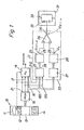
- a multi-channel radio device has a channel switch device 10 with a channel button 11, a mode switch 12 with the switch positions intercom (W), upper band (OB) and lower band (UB), a coding device 13 and a digital display device 14.
- the coding device 13 is connected to a PROM (programmable-read-only-memory) memory circuit 15.
- a first, second and third line connection 16, 17 and 21 lead from the PROM memory circuit to a PLL (phase-locked-loop) oscillator circuit 18, the output of which is connected to a mixer stage of the receiving part of the radio.
- a first, second and third branch 160, 170 and 210 of the first to third line connections 16, 17 and 21 lead to a logic logic circuit 22 which comprises the following construction stages.
- An evaluator 23 connected to branches 160, 170 and 210 is connected to a reference voltage switch 24, the output 25 of which is connected to a non-inverting input of an operational amplifier 26 connected as a differential amplifier.
- a digital / analog converter 28, whose output 29 is connected to an inverting input of the operational amplifier 26, is also connected to the branch 160 or the first line connection 16 via an adaptation stage 27.
- the adaptation stage-27 is a stage, for example formed by a buffer circuit, for adapting the output signal level of the PROM memory circuit 15 to the input of the digital / analog converter 28 and / or a stage for adapting the digital value on the first line connection 16 to that for the Digital / analog converter 28 required input digital value.
- An output 30 of the operational amplifier 26 is connected to an electronically tunable one Selection circuit 31 on, that is for example a high-frequency input circuit 32, the capacitance of which is partly formed by a capacitance variation diode 33.
- FIG. 2 In the more detailed block diagram in FIG. 2, construction stages corresponding to FIG. 1 are designated with the same reference numbers.
- the operation of the circuit described in FIGS. 1 and 2 is as follows.
- the coding device 13 inputs digital information, for example in the BCD code, which firstly contains the reception frequency of the radio channel set, secondly the selected operating mode (two-way communication or conditional two-way communication) and thirdly the selected band (upper band or lower band). This information is fed to the PROM memory circuit 15.
- the PROM memory circuit is first programmed in such a way that it outputs a digital value via the first line connection 16 to the PLL circuit 18 in accordance with the selected radio channel - if this is a permissible radio channel at all.
- the digital value corresponds to a certain division ratio, by which the PLL oscillator circuit is influenced in such a way that it outputs a certain oscillator frequency at its output, which is mixed in a mixing stage of the receiving part of the radio with the respective receiving frequency and forms a (first) intermediate frequency.
- the PROM memory circuit is programmed to over the second Line connection 17 outputs a digital value to the PLL oscillator circuit, which causes the oscillator frequencies generated to lie in the desired frequency grid.
- the PROM memory circuit also delivers a signal identifying the selected operating mode via the line connection 21.
- the last-mentioned signal can optionally also be derived directly from the operating mode switch 12; see. in Fig. 1 dashed line connections.
- the distance between the individual radio channels, i.e. the frequency grid, is 20 kHz or 25 kHz, for example.
- the evaluator 23 makes the following distinctions based on the signals brought to the logic logic circuit 22 via the first to third line connections 16, 17, 21 and the branches 160, 170, 210. It determines whether the operating mode "two-way communication" or “conditional two-way communication", whether a frequency of the upper band or the lower band and which channel grid has been selected with the channel switch device. A number of logic gates 35 are required for these distinctions.
- the evaluator 23 emits an output signal at its outputs, with which the reference voltage switch 24 is controlled. In the exemplary embodiment according to FIG.
- the evaluator 23 has six outputs 36 to 41, of which the outputs 36 and 37 are the upper band or lower band of the 20 k H z raster, the outputs 38 and 39 are the lower band or upper band of the 25th -kHz grid and the outputs 40 and 41 correspond to the intercom frequencies in the 25 kHz grid and in the 20 kHz grid, respectively.
- each of the outputs 36 to 41 is an electro controllable by the output signal African switch 42 to 47 assigned, with which an adjusting resistor 48 can be switched on.
- the adjusting resistors 48 are connected to a fixed DC voltage potential U and with their other connection via one of each of the switches 42 to 47 to the non-inverting input of the operational amplifier 26.
- Different settings of the adjusting resistors 48 lie at the non-inverting input of the operational amplifier 26, each after which of the switches 42 to 47 is closed, one of several reference voltages U ref1 ... 6 .
- the digital value which is guided from the line connection 16 or the branch 160 to the adaptation stage 27 and is dependent on the desired frequency is converted, for example, in the adaptation circuit into a correspondingly different digital value with which the digital / analog converter 28 can be controlled.
- U a and Ur ef By subtracting the voltages U a and Ur ef by means of the operational amplifier 26, one of the control voltages U St1 ... n is obtained at the output 30 of the operational amplifier.
- the respective control voltage is supplied to the capacitance variation diode 33 in such a way that its capacitance value changes in such a way that the selection circuit is tuned to the desired resonance frequency (reception frequency).
- the PROM memory circuit 15 If the operating mode switch 12 is in the switch position "two-way communication" (W), the PROM memory circuit 15 outputs a signal identifying the operating mode to the third connecting line 21, which signal is recognized by the evaluator 23. In connection with that by the Evaluator also determined channel grid of 20 kHz or 25 kHz, for example, one of the switches 46, 47 is then closed and a reference voltage U ref5 or U ref6 corresponding to the two-way communication and the relevant grid is generated. In parallel, the digital / analog converter 28 delivers an output voltage U a , which depends on the selected channel or the desired frequency. By forming the difference in the operational amplifier 26, a control voltage U St is then obtained which tunes the selection circuit 31 in the manner already mentioned above.
Abstract
Description
Die Erfindung geht aus von einem Vielkanal-Sprechfunkgerät nach der Gattung des Hauptanspruchs.The invention is based on a multi-channel radio device according to the preamble of the main claim.
Es sind Vielkanal-Sprechfunkgeräte bekannt, die für die Betriebsarten "Wechselsprechen" und/oder "bedingtes Gegensprechen" geeignet sind. Der jeweils gewünschte Funkkanal wird mit einer Kanaltaste eingestellt, durch die eine PROM-(programmable-read-only-memory-)Speicherschaltung angesteuert wird. Die PROM-Speicherschaltung gibt an ihrem Ausgang kodierte Signale ab, die zum Ansteuern einer PLL-(phase-locked-loop-)Oszillatorschaltung dienen. Die PROM-Speicherschaltung ist derart programmiert, daß sie nur Kodesignale für zugelassene Funkkanäle abgibt. Der Kanalabstand beträgt wahlweise 20 oder 25 kHz. Ein derartiges Vielkanal-Sprechfunkgerät hat den Nachteil, daß es fest abgestimmte, bei der Betriebsart "bedingtes Gegensprechen" auf das Oberband oder Unterband umschaltbare Eingangskreise mit einer Schaltbandbreite von bis zu 5 MHz aufweist. Eine universelle Anwendbarkeit des Vielkanal-Sprechfunkgerätes in dem gesamten zur Verfügung stehenden Sprechfunk-Frequenzbereich ist somit nicht möglich.Multichannel two-way radios are known which are suitable for the “intercom” and / or “conditional intercom” modes. The desired radio channel is set with a channel button, which is used to control a PROM (programmable-read-only-memory) memory circuit. The PROM memory circuit emits coded signals at its output which are used to drive a PLL (phase-locked-loop) oscillator circuit. The PROM memory circuit is programmed in such a way that it only emits code signals for approved radio channels. The channel spacing is either 20 or 25 kHz. Such a multichannel two-way radio has the disadvantage that it has fixedly tuned input circuits with a switching bandwidth of up to 5 MHz which can be switched to the upper band or lower band in the operating mode "conditional two-way communication". Universal applicability of the multi-channel radio device in the entire available radio frequency range is therefore not possible.
Das erfindungsgemäße Vielkanal-Sprechfunkgerät mit den kennzeichnenden Merkmalen des Hauptanspruchs hat den Vorteil, daß die Hochfrequenz-Eingangskreise des Sprechfunkgerätes für jeden gewählten Funkkanal optimal abgestimmt werden.The multi-channel walkie-talkie according to the invention with the characterizing features of the main claim has the advantage that the high-frequency input circuits of the walkie-talkie are optimally coordinated for each selected radio channel.
Durch die in den Unteransprüchen aufgeführten Maßnahmen sind vorteilhafte Weiterbildungen und Verbesserungen des im Hauptanspruch angegebenen Vielkanal-Sprechfunkgerätes möglich. Besonders vorteilhaft ist ein Vielkanal-Sprechfunkgerät, bei dem die logische Verknüpfungsschaltung Schaltmittel enthält, mit denen durch Differenzbildung zwischen einer Referenzspannung, deren Größe von der Betriebsart, dem Frequenzband (Oberband oder Unterband) und dem Kanalraster abhängt, und einer aus dem ersten Digitalwert abgeleiteten analogen Spannung die Steuerspannung erzeugt wird. Auf diese einfache Weise kann eine Steuerspannung bereitgestellt werden, die den Selektionskreis oder die Selektionskreise des Empfangsteils des Sprechfunkgerätes exakt auf die Empfangsfrequenz abstimmt.The measures listed in the subclaims allow advantageous developments and improvements of the multichannel radio set specified in the main claim. A multi-channel walkie-talkie is particularly advantageous, in which the logic combination circuit contains switching means with which, by forming the difference between a reference voltage, the size of which depends on the operating mode, the frequency band (upper band or lower band) and the channel grid, and an analogue derived from the first digital value Voltage the control voltage is generated. In this simple manner, a control voltage can be provided which precisely matches the selection circuit or the selection circuits of the receiving part of the radio device to the reception frequency.
Ein Ausführungsbeispiel der Erfindung ist in der Zeichnung anhand zweier Figuren dargestellt und in der nachfolgenden Beschreibung näher erläutert. Die Zeichnung zeigt in
- Fig. 1 ein stark vereinfachtes Blockschaltbild eines Empfangsteils eines erfindungsgemäßen Vielkanal-Sprechfunkgerätes und
- Fig. 2 ein ausführlicheres Blockschaltbild zu Fig. 1.
- Fig. 1 is a greatly simplified block diagram of a receiving part of a multi-channel radio device according to the invention and
- FIG. 2 shows a more detailed block diagram for FIG. 1.
Ein erfindungsgemäßes Vielkanal-Sprechfunkgerät hat eine Kanalschaltereinrichtung 10 mit einer Kanaltaste 11, einem Betriebsartenschalter 12 mit den Schalterstellungen Wechselsprechen (W), Oberband (OB) und Unterband (UB), eine Kodiereinrichtung 13 und eine digitale Anzeigevorrichtung 14. iA multi-channel radio device according to the invention has a
Die Kodiereinrichtung 13 ist mit einer PROM-(programmable- read-only-memory-)Speicherschaltung 15 verbunden. Von der PROM-Speicherschaltung führen eine erste, zweite und dritte Leitungsverbindung 16, 17 und 21 an eine PLL-(phase-locked- loop-)Oszillatorschaltung 18, deren Ausgang mit einer Mischstufe des Empfangsteils des Sprechfunkgerätes in Verbindung steht. Ein erster, zweiter und dritter Abzweig 160, 170 und 210 der ersten bis dritten Leitungsverbindung 16, 17 und 21 führen an eine logische Verknüpfungsschaltung 22, die folgende Baustufen umfaßt. Ein mit den Abzweigen 160, 170 und 210 verbundener Auswerter 23 steht mit einem Referenzspannungsschalter 24 in Verbindung, dessen Ausgang 25 mit einem nichtinvertierenden Eingang eines als Differenzverstärker geschalteten Operationsverstärkers 26 verbunden ist. Mit dem Abzweig 160 bzw. der ersten Leitungsverbindung 16 ist weiterhin über eine Anpassungsstufe 27 ein Digital/ Analog-Wandler 28 verbunden, dessen Ausgang 29 mit einem invertierenden Eingang des Operationsverstärkers 26 in Verbindung steht. Die Anpassungsstufe-27 ist eine zum Beispiel durch einen Pufferkreis gebildete Stufe zum Anpassen des Ausgangssignalpegels der PROM-Speicherschaltung 15 an den Eingang des Digital/Analog-Wandlers 28 und/oder einer Stufe zum Anpassen des Digitalwertes auf der ersten Leitungsverbindung 16 an den für den Digital/Analog-Wandler 28 benötigten Eingangs-Digitalwert. An einen Ausgang 30 des Operationsverstärkers 26 schließt sich eine elektronisch abstimmbare Selektionsschaltung 31 an, das ist zum Beispiel ein Hochfrequenz-Eingangskreis 32, dessen Kapazität zu einem Teil von einer Kapazitätsvariationsdiode 33 gebildet wird.The
In dem ausführlicheren Blockschaltbild in Fig. 2 sind der Fig. 1 entsprechende Baustufen mit gleichen Bezugszahlen bezeichnet. Die Wirkungsweise der in den Fig. 1 und 2 beschriebenen Schaltung ist folgende.In the more detailed block diagram in FIG. 2, construction stages corresponding to FIG. 1 are designated with the same reference numbers. The operation of the circuit described in FIGS. 1 and 2 is as follows.
Befindet sich der Betriebsartenschalter 12 in der Schalterstellung Oberband (OB) oder Unterband (UB) und ist mit der Kanaltaste 11 bzw. den Kanaltasten ein bestimmter Funkkanal aus einer Vielzahl von Funkkanälen ausgewählt worden, zum Beispiel der Funkkanal 210, so gibt die Kodiereinrichtung 13 eine digitale Information, zum Beispiel im BCD-Kode, ab, die erstens die Empfangsfrequenz des eingestellten Funkkanals, zweitens die gewählte Betriebsart (Wechselsprechen oder bedingtes Gegensprechen) und drittens das gewählte Band (Oberband oder Unterband) zum Inhalt hat. Diese Information wird der PROM-Speicherschaltung 15 zugeführt.If the
Die PROM-Speicherschaltung ist erstens derart programmiert, daß sie entsprechend dem gewählten Funkkanal - sofern dies überhaupt ein zulässiger Funkkanal ist - einen Digitalwert über die erste Leitungsverbindung 16 an die PLL-Schaltung 18 abgibt. Der Digitalwert entspricht einem bestimmten Teilungsverhältnis, durch das die PLL-Oszillatorschaltung derart beeinflußt wird, daß sie an ihrem Ausgang eine bestimmte Oszillatorfrequenz abgibt, die in einer Mischstufe des Empfangsteils des Sprechfunkgerätes mit der jeweiligen Empfangsfrequenz gemischt wird und eine (erste) Zwischenfrequenz bildet. Die PROM-Speicherschaltung ist zweitens derart programmiert, daß sie über die zweite Leitungsverbindung 17 einen Digitalwert an die PLL-Oszillatorschaltung abgibt, der bewirkt, daß die erzeugten Oszillatorfrequenzen in dem gewünschten Frequenzraster liegen. Die PROM-Speicherschaltung liefert außerdem über die Leitungsverbindung 21 ein die gewählte Betriebsart kennzeichnendes Signal. Das zuletzt genannte Signal kann gegebenenfalls auch unmittelbar von dem Betriebsartenschalter 12 abgeleitet werden; vgl. in Fig. 1 gestrichelt eingezeichnete Leitungsverbindungen. Der Abstand zwischen den einzelnen Funkkanälen, das heißt das Frequenzraster, beträgt beispielsweise 20 kHz oder 25 kHz.The PROM memory circuit is first programmed in such a way that it outputs a digital value via the
Anhand der über die erste bis dritte Leitungsverbindung 16, 17, 21 und die Abzweige 160, 170, 210 an die logische Verknüpfungsschaltung 22 herangeführten Signale trifft der Auswerter 23 folgende Unterscheidungen. Er stellt fest, ob die Betriebsart "Wechselsprechen" oder "bedingtes Gegensprechen", ob eine Frequenz des Oberbandes oder des Unterbandes und welches Kanalraster mit der Kanalschaltereinrichtung gewählt worden ist. Für diese Unterscheidungen ist eine Reihe von logischen Verknüpfungsgliedern 35 erforderlich. Der Auswerter 23 gibt an seinen Ausgängen ein Ausgangssignal ab, mit dem der Referenzspannungsschalter 24 angesteuert wird. In dem Ausführungsbeispiel nach Fig. 2 hat der Auswerter 23 sechs Ausgänge 36 bis 41, von denen die Ausgänge 36 und 37 dem Oberband bzw. Unterband des 20-kHz-Rasters, die Ausgänge 38 und 39 dem Unterband bzw. Oberband des 25-kHz-Rasters und die Ausgänge 40 und 41 den Wechselsprechfrequenzen im 25-kHz-Raster bzw. im 20-kHz-Raster entsprechen.The
In dem Referenzspannungsschalter 24 ist jedem der Ausgänge 36 bis 41 ein durch das Ausgangssignal steuerbarer elektronischer Schalter 42 bis 47 zugeordnet, mit dem je ein Einstellwiderstand 48 eingeschaltet werden kann. Die Einstellwiderstände 48 liegen mit ihrem einen Anschluß an einem festen Gleichspannungspotential U und mit ihrem anderen Anschluß über je einen der Schalter 42 bis 47 an dem nichtinvertierenden Eingang des Operationsverstärkers 26. Durch verschiedene Einstellungen der Einstellwiderstände 48 liegt an dem nichtinvertierenden Eingang des Operationsverstärkers 26, je nachdem, welcher der Schalter 42 bis 47 geschlossen ist, eine von mehreren Referenzspannungen Uref1...6.In the
Der von der Leitungsverbindung 16 bzw. dem Abzweig 160 an die Anpassungsstufe 27 geführte, von der gewünschten Frequenz abhängige Digitalwert wird beispielsweise in der Anpassungsschaltung in einen entsprechend anderen Digitalwert umgewandelt, mit dem der Digital/Analog-Wandler 28 angesteuert werden kann. Am Ausgang 29 des Digital/Analog-Wandlers 28 steht eine Ausgangsspannung U , deren Spannungswert von der gewünschten Frequenz abhängt. Durch Subtraktion der Spannungen U a und Uref mittels des Operationsverstärkers 26 erhält man am Ausgang 30 des Operationsverstärkers eine der Steuerspannungen USt1...n. Die jeweilige Steuerspannung wird der Kapazitätsvariationsdiode 33 derart zugeführt, daß sich deren Kapazitätswert derart ändert, daß der Selektionskreis auf die gewünschte Resonanzfrequenz (Empfangsfrequenz) abgestimmt wird.The digital value which is guided from the
Befindet sich der Betriebsartenschalter 12 in der Schalterstellung "Wechselsprechen" (W), so gibt die PROM-Speicherschaltung 15 an die dritte Verbindungsleitung 21 ein die Betriebsart kennzeichnendes Signal ab, das von dem Auswerter 23 erkannt wird. In Verbindung mit dem durch den Auswerter ebenfalls festgestellten Kanalraster von zum Beispiel 20 kHz oder 25 kHz wird dann einer der Schalter 46, 47 geschlossen und eine dem Wechselsprechen und dem betreffenden Raster entsprechende Referenzspannung Uref5 oder Uref6 erzeugt. Parallel dazu liefert der Digital/ Analog-Wandler 28 eine Ausgangsspannung Ua, die von dem gewählten Kanal bzw. der gewünschten Frequenz abhängt. Durch Differenzbildung in dem Operationsverstärker 26 erhält man dann eine Steuerspannung USt, die den Selektionskreis 31 in der bereits oben erwähnten Weise abstimmt.If the
Claims (9)
Priority Applications (1)
| Application Number | Priority Date | Filing Date | Title |
|---|---|---|---|
| AT81101731T ATE7831T1 (en) | 1980-08-28 | 1981-03-10 | MULTI-CHANNEL TRANSCEIVER FOR 'INTERCOM' AND/OR 'CONDITIONAL INTERCOM' OPERATING MODES. |
Applications Claiming Priority (2)
| Application Number | Priority Date | Filing Date | Title |
|---|---|---|---|
| DE19803032378 DE3032378A1 (en) | 1980-08-28 | 1980-08-28 | MULTI-CHANNEL RADIO FOR THE OPERATING MODE INTERACTION AND / OR CONDITIONAL INTERCOM |
| DE3032378 | 1980-08-28 |
Publications (3)
| Publication Number | Publication Date |
|---|---|
| EP0046835A2 true EP0046835A2 (en) | 1982-03-10 |
| EP0046835A3 EP0046835A3 (en) | 1982-09-01 |
| EP0046835B1 EP0046835B1 (en) | 1984-06-06 |
Family
ID=6110558
Family Applications (1)
| Application Number | Title | Priority Date | Filing Date |
|---|---|---|---|
| EP81101731A Expired EP0046835B1 (en) | 1980-08-28 | 1981-03-10 | Multichannel radiotelecommunication apparatus for the operating modes "two-way speech communication" and/or "alternating duplex communication" |
Country Status (3)
| Country | Link |
|---|---|
| EP (1) | EP0046835B1 (en) |
| AT (1) | ATE7831T1 (en) |
| DE (2) | DE3032378A1 (en) |
Cited By (5)
| Publication number | Priority date | Publication date | Assignee | Title |
|---|---|---|---|---|
| EP0119439A2 (en) * | 1983-03-16 | 1984-09-26 | ANT Nachrichtentechnik GmbH | Diode mixer with bias control and its application |
| WO1987002202A1 (en) * | 1985-10-01 | 1987-04-09 | Plessey Overseas Limited | Frequency alignment circuit and synthesiser therefor |
| GB2194696A (en) * | 1986-03-26 | 1988-03-09 | Gen Electric | Digital radio communications devices |
| US4905305A (en) * | 1986-03-26 | 1990-02-27 | General Electric Company | Method and apparatus for controlling the frequency of operation and at least one further variable operating parameter of a radio communications device |
| EP0394358A1 (en) * | 1988-01-07 | 1990-10-31 | Motorola, Inc. | Low voltage and low power frequency synthesizer |
Families Citing this family (1)
| Publication number | Priority date | Publication date | Assignee | Title |
|---|---|---|---|---|
| DE3626792A1 (en) * | 1986-08-08 | 1988-02-11 | Siemens Ag | Device for stabilising the transmitting and receiving frequency of a transmitting set |
Citations (2)
| Publication number | Priority date | Publication date | Assignee | Title |
|---|---|---|---|---|
| US3715687A (en) * | 1972-04-05 | 1973-02-06 | Gte Sylvania Inc | Non-linear voltage generating apparatus |
| DE2551110A1 (en) * | 1975-11-14 | 1977-05-18 | Bosch Gmbh Robert | Radio transceiver for duplex or semiduplex operation - switches in and out individual transistor oscillators for frequency bands using emitter blocking DC voltages |
-
1980
- 1980-08-28 DE DE19803032378 patent/DE3032378A1/en not_active Withdrawn
-
1981
- 1981-03-10 AT AT81101731T patent/ATE7831T1/en not_active IP Right Cessation
- 1981-03-10 EP EP81101731A patent/EP0046835B1/en not_active Expired
- 1981-03-10 DE DE8181101731T patent/DE3163940D1/en not_active Expired
Patent Citations (2)
| Publication number | Priority date | Publication date | Assignee | Title |
|---|---|---|---|---|
| US3715687A (en) * | 1972-04-05 | 1973-02-06 | Gte Sylvania Inc | Non-linear voltage generating apparatus |
| DE2551110A1 (en) * | 1975-11-14 | 1977-05-18 | Bosch Gmbh Robert | Radio transceiver for duplex or semiduplex operation - switches in and out individual transistor oscillators for frequency bands using emitter blocking DC voltages |
Non-Patent Citations (1)
| Title |
|---|
| "Bosch-Funk, Technische Informationen", Ausgabe 1980, Vielkanal-Sprechfunkgeräte, KF 802 * |
Cited By (11)
| Publication number | Priority date | Publication date | Assignee | Title |
|---|---|---|---|---|
| EP0119439A2 (en) * | 1983-03-16 | 1984-09-26 | ANT Nachrichtentechnik GmbH | Diode mixer with bias control and its application |
| EP0119439A3 (en) * | 1983-03-16 | 1985-11-27 | Ant Nachrichtentechnik Gmbh | Diode mixer with bias control and its application |
| US4593411A (en) * | 1983-03-16 | 1986-06-03 | Ant Nachrichtentech | Diode mixer with bias control |
| WO1987002202A1 (en) * | 1985-10-01 | 1987-04-09 | Plessey Overseas Limited | Frequency alignment circuit and synthesiser therefor |
| GB2194696A (en) * | 1986-03-26 | 1988-03-09 | Gen Electric | Digital radio communications devices |
| US4870699A (en) * | 1986-03-26 | 1989-09-26 | General Electric Company | Method and apparatus for controlling the frequency of operation and at least one further variable operating parameter of a radio communications device |
| US4905305A (en) * | 1986-03-26 | 1990-02-27 | General Electric Company | Method and apparatus for controlling the frequency of operation and at least one further variable operating parameter of a radio communications device |
| US4947454A (en) * | 1986-03-26 | 1990-08-07 | General Electric Company | Radio with digitally controlled audio processor |
| GB2194696B (en) * | 1986-03-26 | 1990-11-21 | Gen Electric | Digital radio communications devices |
| EP0394358A1 (en) * | 1988-01-07 | 1990-10-31 | Motorola, Inc. | Low voltage and low power frequency synthesizer |
| EP0394358A4 (en) * | 1988-01-07 | 1991-04-10 | Motorola, Inc. | Low voltage and low power frequency synthesizer |
Also Published As
| Publication number | Publication date |
|---|---|
| ATE7831T1 (en) | 1984-06-15 |
| EP0046835B1 (en) | 1984-06-06 |
| EP0046835A3 (en) | 1982-09-01 |
| DE3032378A1 (en) | 1982-04-01 |
| DE3163940D1 (en) | 1984-07-12 |
Similar Documents
| Publication | Publication Date | Title |
|---|---|---|
| DE2622594C2 (en) | ||
| DE2929901C2 (en) | Electronic channel selector | |
| DE2854852C2 (en) | Electronic voting unit, in particular for television receivers | |
| DE2312651A1 (en) | REMOTE RECEIVER | |
| EP0314873B1 (en) | Device for automatic application of tuning voltage to tunable components of the intermediate frequency amplifier for television receivers | |
| DE2915860A1 (en) | CONTROL CIRCUIT FOR CONTROLLING SELECTED FUNCTIONS OF A SIGNAL RECEIVER | |
| EP0046835B1 (en) | Multichannel radiotelecommunication apparatus for the operating modes "two-way speech communication" and/or "alternating duplex communication" | |
| DE2333851A1 (en) | METHOD AND ARRANGEMENTS FOR THE INDEPENDENT RE-ADJUSTMENT OF THE OSCILLATOR FREQUENCY, SET WITH A TUNING ARRANGEMENT, OF AN OVERLAY RECEIVER OF A PICTURE AND / OR SOUND REPLAY ARRANGEMENT | |
| DE2460536C2 (en) | tuner | |
| EP0036086A1 (en) | VHF mobile radio with two receiving sections and with two signal seeking devices | |
| EP0025876A1 (en) | Multichannel radiotelephone equipment | |
| DE19650524A1 (en) | Double tuning circuit for TV tuner | |
| EP1033813A2 (en) | Radio receiver system and method for controlling a radio receiver system | |
| DE3707839A1 (en) | ELECTRONIC TUNING DEVICE | |
| DE2916171C2 (en) | ||
| DE2259984B2 (en) | Tuning circuit for a multi-channel receiver for high-frequency electrical oscillations, especially for television receivers | |
| EP0578007A1 (en) | Circuit arrangement for the recognition and suppression of adjacent channel interferece | |
| DE2625131C2 (en) | TV receiver with fully electronic wireless remote control | |
| DE3346981A1 (en) | Audio IF amplifier for a multi-standard television receiver | |
| DE2758951A1 (en) | Receiver for community antenna TV system - shares level and frequency control between all channels | |
| EP0038580A1 (en) | Radio apparatus with a programmable memory for controlling transmitting and receiving channels | |
| EP0285926A2 (en) | Fine tuning method of a HF modulator and arrangement for carrying it out | |
| DE2165163C3 (en) | Channel selector | |
| DE19733583C2 (en) | Electronic device with a switching power supply | |
| EP0290825B1 (en) | Video recorder with a dynamically tunable tuner |
Legal Events
| Date | Code | Title | Description |
|---|---|---|---|
| PUAI | Public reference made under article 153(3) epc to a published international application that has entered the european phase |
Free format text: ORIGINAL CODE: 0009012 |
|
| AK | Designated contracting states |
Designated state(s): AT DE FR GB IT NL |
|
| PUAL | Search report despatched |
Free format text: ORIGINAL CODE: 0009013 |
|
| AK | Designated contracting states |
Designated state(s): AT DE FR GB IT NL |
|
| 17P | Request for examination filed |
Effective date: 19820827 |
|
| ITF | It: translation for a ep patent filed |
Owner name: BARZANO' E ZANARDO ROMA S.P.A. |
|
| GRAA | (expected) grant |
Free format text: ORIGINAL CODE: 0009210 |
|
| AK | Designated contracting states |
Designated state(s): AT DE FR GB IT NL |
|
| REF | Corresponds to: |
Ref document number: 7831 Country of ref document: AT Date of ref document: 19840615 Kind code of ref document: T |
|
| REF | Corresponds to: |
Ref document number: 3163940 Country of ref document: DE Date of ref document: 19840712 |
|
| ET | Fr: translation filed | ||
| PLBE | No opposition filed within time limit |
Free format text: ORIGINAL CODE: 0009261 |
|
| STAA | Information on the status of an ep patent application or granted ep patent |
Free format text: STATUS: NO OPPOSITION FILED WITHIN TIME LIMIT |
|
| 26N | No opposition filed | ||
| ITTA | It: last paid annual fee | ||
| PGFP | Annual fee paid to national office [announced via postgrant information from national office to epo] |
Ref country code: GB Payment date: 19980226 Year of fee payment: 18 |
|
| PGFP | Annual fee paid to national office [announced via postgrant information from national office to epo] |
Ref country code: FR Payment date: 19980320 Year of fee payment: 18 |
|
| PGFP | Annual fee paid to national office [announced via postgrant information from national office to epo] |
Ref country code: NL Payment date: 19980326 Year of fee payment: 18 Ref country code: AT Payment date: 19980326 Year of fee payment: 18 |
|
| PGFP | Annual fee paid to national office [announced via postgrant information from national office to epo] |
Ref country code: DE Payment date: 19980523 Year of fee payment: 18 |
|
| PG25 | Lapsed in a contracting state [announced via postgrant information from national office to epo] |
Ref country code: GB Free format text: LAPSE BECAUSE OF NON-PAYMENT OF DUE FEES Effective date: 19990310 Ref country code: AT Free format text: LAPSE BECAUSE OF NON-PAYMENT OF DUE FEES Effective date: 19990310 |
|
| PG25 | Lapsed in a contracting state [announced via postgrant information from national office to epo] |
Ref country code: NL Free format text: LAPSE BECAUSE OF NON-PAYMENT OF DUE FEES Effective date: 19991001 |
|
| GBPC | Gb: european patent ceased through non-payment of renewal fee |
Effective date: 19990310 |
|
| PG25 | Lapsed in a contracting state [announced via postgrant information from national office to epo] |
Ref country code: FR Free format text: LAPSE BECAUSE OF NON-PAYMENT OF DUE FEES Effective date: 19991130 |
|
| NLV4 | Nl: lapsed or anulled due to non-payment of the annual fee |
Effective date: 19991001 |
|
| REG | Reference to a national code |
Ref country code: FR Ref legal event code: ST |
|
| PG25 | Lapsed in a contracting state [announced via postgrant information from national office to epo] |
Ref country code: DE Free format text: LAPSE BECAUSE OF NON-PAYMENT OF DUE FEES Effective date: 20000101 |