EP0285926A2 - Fine tuning method of a HF modulator and arrangement for carrying it out - Google Patents
Fine tuning method of a HF modulator and arrangement for carrying it out Download PDFInfo
- Publication number
- EP0285926A2 EP0285926A2 EP88104806A EP88104806A EP0285926A2 EP 0285926 A2 EP0285926 A2 EP 0285926A2 EP 88104806 A EP88104806 A EP 88104806A EP 88104806 A EP88104806 A EP 88104806A EP 0285926 A2 EP0285926 A2 EP 0285926A2
- Authority
- EP
- European Patent Office
- Prior art keywords
- tuning
- modulator
- amplified
- level
- signal
- Prior art date
- Legal status (The legal status is an assumption and is not a legal conclusion. Google has not performed a legal analysis and makes no representation as to the accuracy of the status listed.)
- Withdrawn
Links
Images
Classifications
-
- H—ELECTRICITY
- H03—ELECTRONIC CIRCUITRY
- H03C—MODULATION
- H03C3/00—Angle modulation
- H03C3/02—Details
- H03C3/09—Modifications of modulator for regulating the mean frequency
Definitions
- the invention relates to a method for fine tuning an RF modulator, which is operated in a video recorder with an automatically tunable tuner and which contains a voltage-controlled oscillator for tuning, and an arrangement for carrying out the method.
- the invention has for its object to provide a method of the type specified in the preamble of claim 1 so that a quick and precise modulator tuning is ensured and yet only a small technical effort is required for an arrangement for performing the method.
- the output signal of the voltage-controlled oscillator set on a specific channel is amplified via the tuned and tuned accordingly.
- the level of the amplified oscillator signal is then evaluated and, depending on this, a control signal is formed which changes the tuning of the modulator until the level of the amplified oscillator signal reaches a maximum.
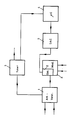
- the block circuit shown shows a modulator 6 to be tuned with a voltage-controlled oscillator 2, the output of which is connected via a signal path 1 to the input of a tuner 3 which is present in the video recorder and is preferably automatically adjustable anyway.
- signal path 1 is designed as a switchable antenna amplifier which allows the tuner to be supplied with either the oscillator signal required for modulator tuning or an antenna signal required for reception.
- An output of the tuner 3 is connected to a microcomputer 4 which is also present in the video recorder and whose control output is connected to the control input of the oscillator 2 via a digital-to-analog converter 5.
- the same channel is selected both for the self-tuning tuner 3 and for the oscillator 2.
- the level of the oscillator signal amplified for dynamic modulator fine tuning via the tuned tuner is then evaluated in the microcomputer 4.
- the microcomputer in turn delivers a digital control signal depending on the level of the amplified oscillator signal the digital-to-analog converter (DAC) 5 is converted into an analog control voltage and supplied to the voltage-controlled oscillator 2.
- DAC digital-to-analog converter
- the arrangement according to the invention is particularly characterized by the low technical complexity, since the "tuner” and “microcomputer” devices used for tuning are present in a video recorder anyway. Compared to known modulator tuning circuits in video recorders, this means that a complete PLL circuit can be omitted.
Landscapes
- Input Circuits Of Receivers And Coupling Of Receivers And Audio Equipment (AREA)
- Television Signal Processing For Recording (AREA)
Abstract
Description
Die Erfindung betrifft ein Verfahren zur Feinabstimmung eines HF-Modulators, der in einem Videorecorder mit automatisch abgleichbarem Tuner betrieben wird und der zur Abstimmung einen spannungsgesteuerten Oszillator enthält, sowie eine Anordnung zur Durchführung des Verfahrens.The invention relates to a method for fine tuning an RF modulator, which is operated in a video recorder with an automatically tunable tuner and which contains a voltage-controlled oscillator for tuning, and an arrangement for carrying out the method.
Zur Abstimmung des HF-Modulators in einem Videorecorder ist es bekannt, den hierzu vorgesehenen spannungsgesteuerten Oszillator entweder per Hand mit Hilfe eines Potentiometers oder automatisch mittels einer Regelschleife (PLL) abzugleichen. Beide Möglichkeiten haben jedoch Nachteile. So erfordert die Handabstimmung einen hohen Zeitaufwand und führt außerdem nur zu einem relativ groben Abgleich. Demgegenüber arbeitet die automatische Abstimmung mittels PLL-Schleife zwar schnell und sehr präzise, erfordert jedoch einen wesentlich höheren technischen und kostenmäßigen Aufwand.To tune the RF modulator in a video recorder, it is known to adjust the voltage-controlled oscillator provided for this purpose either manually using a potentiometer or automatically using a control loop (PLL). However, both options have disadvantages. Manual tuning takes a lot of time and also only leads to a relatively rough comparison. In contrast, the automatic adjustment using a PLL loop works quickly and very precisely, but requires a much higher technical and cost effort.
Der Erfindung liegt die Aufgabe zugrunde, ein Verfahren der im Oberbegriff des Anspruchs 1 angegebenen Art so auszubilden, daß eine schnelle und präzise Modulatorabstimmung gewährleistet ist und dennoch nur ein geringer technischer Aufwand für eine Anordnung zur Durchführung des Verfahrens erforderlich ist.The invention has for its object to provide a method of the type specified in the preamble of claim 1 so that a quick and precise modulator tuning is ensured and yet only a small technical effort is required for an arrangement for performing the method.
Diese Aufgabe wird gemäß der Erfindung durch die im Kennzeichen des Anspruchs 1 angegebenen Maßnahmen gelöst. Ein Ausführungsbeispiel für eine Anordnung zur Durchführung des Verfahrens gemäß der Erfindung ist im Unteranspruch gekennzeichnet.This object is achieved according to the invention by the measures specified in the characterizing part of claim 1. An embodiment of an arrangement for carrying out the method according to the invention is characterized in the subclaim.
Bei dem Verfahren gemäß der Erfindung wird das Ausgangssignal des auf einen bestimmten Kanal eingestellten spannungsgesteuerten Oszillators über den entsprechend abgestimmten und abgeglichenen Tuner verstärkt. Anschließend wird der Pegel des verstärkten Oszillatorsignals ausgewertet und in Abhängigkeit hiervon ein Regelsignal gebildet, das die Abstimmung des Modulators solange verändert, bis der Pegel des verstärkten Oszillatorsignals ein Maximum erreicht.In the method according to the invention, the output signal of the voltage-controlled oscillator set on a specific channel is amplified via the tuned and tuned accordingly. The level of the amplified oscillator signal is then evaluated and, depending on this, a control signal is formed which changes the tuning of the modulator until the level of the amplified oscillator signal reaches a maximum.
Eine Anordnung zur Durchführung des Verfahrens gemäß der Erfindung ist im folgenden anhand einer Zeichnung näher erläutert.An arrangement for carrying out the method according to the invention is explained in more detail below with reference to a drawing.
Die dargestellte Blockschaltung zeigt einen abzustimmenden Modulator 6 mit einem spannungsgesteuerten Oszillator 2, dessen Ausgang über einen Signalweg 1 mit dem Eingang eines im Videorecorder ohnehin vorhandenen, vorzugsweise automatisch abgleichbaren Tuners 3 verbunden ist. Der Signalweg 1 ist bei dem hier gezeigten Beispiel als umschaltbarer Antennenverstärker ausgebildet, der es erlaubt, dem Tuner wahlweise das für die Modulatorabstimmung benötigte Oszillatorsignal, oder ein für den Empfang benötigtes Antennensignal zuzuführen. Ein Ausgang des Tuners 3 steht mit einem gleichfalls im Videorecorder bereits vorhandenen Mikrocomputer 4 in Verbindung, dessen Regelausgang über einen Digital-Analog-Converter 5 an den Steuereingang des Oszillators 2 angeschlossen ist.The block circuit shown shows a
Zunächst wird sowohl für den selbstabgleichenden Tuner 3 als auch für den Oszillator 2 der gleiche Kanal gewählt. Das zur dynamischen Modulatorfeinabstimmung über den abgeglichenen Tuner verstärkte Oszillatorsignal wird dann pegelmäßig im Mikrocomputer 4 ausgewertet. Der Mikrocomputer wiederum liefert in Abhängigkeit vom Pegel des verstärkten Oszillatorsignals ein digitales Regelsignal, das über den Digital-Analog-Converter (DAC) 5 in eine analoge Regelspannung umgewandelt und dem spannungsgesteuerten Oszillator 2 zugeführt wird. Die optimale Abstimmung des Modulators ist erreicht, wenn der Pegel des verstärkten Oszillatorsignals maximal wird.First, the same channel is selected both for the self-
Die Anordnung gemäß der Erfindung zeichnet sich besonders durch den geringen technischen Aufwand aus, da die zur Abstimmung benutzten Einrichtungen "Tuner" und "Mikrocomputer" in einem Videorecorder ohnehin vorhanden sind. Im Vergleich zu bekannten Modulator-Abstimmschaltungen in Videorecordern kann hierdurch ein vollständiger PLL-Kreis entfallen.The arrangement according to the invention is particularly characterized by the low technical complexity, since the "tuner" and "microcomputer" devices used for tuning are present in a video recorder anyway. Compared to known modulator tuning circuits in video recorders, this means that a complete PLL circuit can be omitted.
Claims (2)
Applications Claiming Priority (2)
| Application Number | Priority Date | Filing Date | Title |
|---|---|---|---|
| DE3711983 | 1987-04-09 | ||
| DE19873711983 DE3711983A1 (en) | 1987-04-09 | 1987-04-09 | METHOD FOR TUNING AN RF MODULATOR AND ARRANGEMENT FOR CARRYING OUT THE METHOD |
Publications (2)
| Publication Number | Publication Date |
|---|---|
| EP0285926A2 true EP0285926A2 (en) | 1988-10-12 |
| EP0285926A3 EP0285926A3 (en) | 1990-03-21 |
Family
ID=6325220
Family Applications (1)
| Application Number | Title | Priority Date | Filing Date |
|---|---|---|---|
| EP88104806A Withdrawn EP0285926A3 (en) | 1987-04-09 | 1988-03-25 | Fine tuning method of a hf modulator and arrangement for carrying it out |
Country Status (2)
| Country | Link |
|---|---|
| EP (1) | EP0285926A3 (en) |
| DE (2) | DE3711983A1 (en) |
Cited By (1)
| Publication number | Priority date | Publication date | Assignee | Title |
|---|---|---|---|---|
| EP0320598A2 (en) * | 1987-12-16 | 1989-06-21 | GRUNDIG E.M.V. Elektro-Mechanische Versuchsanstalt Max Grundig holländ. Stiftung & Co. KG. | Tuning method for a HF modulator |
Families Citing this family (2)
| Publication number | Priority date | Publication date | Assignee | Title |
|---|---|---|---|---|
| DE4121027A1 (en) * | 1991-06-26 | 1993-01-07 | Thomson Brandt Gmbh | ARRANGEMENT FOR A VIDEO AND SOUND MODULATOR |
| JP4705039B2 (en) † | 2004-10-08 | 2011-06-22 | 株式会社村上開明堂 | Mirror surface angle adjustment device |
Citations (2)
| Publication number | Priority date | Publication date | Assignee | Title |
|---|---|---|---|---|
| US4334323A (en) * | 1980-09-08 | 1982-06-08 | Zenith Radio Corporation | Self tracking tuner |
| US4500920A (en) * | 1981-07-01 | 1985-02-19 | Alps Electric Co., Ltd. | RF Modulator |
-
1987
- 1987-04-09 DE DE19873711983 patent/DE3711983A1/en not_active Withdrawn
-
1988
- 1988-03-25 EP EP88104806A patent/EP0285926A3/en not_active Withdrawn
- 1988-03-25 DE DE8817129U patent/DE8817129U1/en not_active Expired - Lifetime
Patent Citations (2)
| Publication number | Priority date | Publication date | Assignee | Title |
|---|---|---|---|---|
| US4334323A (en) * | 1980-09-08 | 1982-06-08 | Zenith Radio Corporation | Self tracking tuner |
| US4500920A (en) * | 1981-07-01 | 1985-02-19 | Alps Electric Co., Ltd. | RF Modulator |
Cited By (2)
| Publication number | Priority date | Publication date | Assignee | Title |
|---|---|---|---|---|
| EP0320598A2 (en) * | 1987-12-16 | 1989-06-21 | GRUNDIG E.M.V. Elektro-Mechanische Versuchsanstalt Max Grundig holländ. Stiftung & Co. KG. | Tuning method for a HF modulator |
| EP0320598A3 (en) * | 1987-12-16 | 1990-02-28 | Grundig E.M.V. Elektro-Mechanische Versuchsanstalt Max Grundig Holland. Stiftung & Co. Kg. | Tuning method for a hf modulator |
Also Published As
| Publication number | Publication date |
|---|---|
| DE3711983A1 (en) | 1988-10-27 |
| EP0285926A3 (en) | 1990-03-21 |
| DE8817129U1 (en) | 1993-03-04 |
Similar Documents
| Publication | Publication Date | Title |
|---|---|---|
| DE2843809A1 (en) | DEVICE FOR CONTROLLING THE SETTING OF SEVERAL VARIABLE SIZES ON ONE ELECTRONIC DEVICE | |
| DE3308690A1 (en) | METHOD FOR TUNING THE VIBRATION CIRCLES OF A MESSAGE RECEIVER | |
| DE2854852C2 (en) | Electronic voting unit, in particular for television receivers | |
| EP0043536A2 (en) | Control system to adjust a physical value | |
| EP0314873B1 (en) | Device for automatic application of tuning voltage to tunable components of the intermediate frequency amplifier for television receivers | |
| DE3406150C2 (en) | ||
| DE3036351A1 (en) | SEARCH TUNING SYSTEM WITH DIRECTLY ADDRESSING CHANNEL SELECTION | |
| DE2333851A1 (en) | METHOD AND ARRANGEMENTS FOR THE INDEPENDENT RE-ADJUSTMENT OF THE OSCILLATOR FREQUENCY, SET WITH A TUNING ARRANGEMENT, OF AN OVERLAY RECEIVER OF A PICTURE AND / OR SOUND REPLAY ARRANGEMENT | |
| DE3242965C1 (en) | Tuning unit for telecommunications equipment | |
| EP0148389B1 (en) | Tuning system for a television receiver | |
| EP0285926A2 (en) | Fine tuning method of a HF modulator and arrangement for carrying it out | |
| EP0046835B1 (en) | Multichannel radiotelecommunication apparatus for the operating modes "two-way speech communication" and/or "alternating duplex communication" | |
| DE3707839A1 (en) | ELECTRONIC TUNING DEVICE | |
| DE2830668C2 (en) | ||
| DE2031294C3 (en) | Abbnmvorrichtung for high-frequency electrical vibrations | |
| EP0290825B1 (en) | Video recorder with a dynamically tunable tuner | |
| DE3346981A1 (en) | Audio IF amplifier for a multi-standard television receiver | |
| DE1466222C3 (en) | Method for increasing the setting accuracy of a heterodyne receiver with digital display | |
| DE4102562A1 (en) | METHOD AND CIRCUIT FOR AN AUTOMATIC, HIGH-PRECISION FREQUENCY TUNING | |
| DE2758951A1 (en) | Receiver for community antenna TV system - shares level and frequency control between all channels | |
| EP0320598B1 (en) | Tuning method for a hf modulator | |
| DE3243652A1 (en) | ARRANGEMENT FOR CONTROLLING THE AUTOMATIC FINE TUNING OF A RECEIVER | |
| DE3742654A1 (en) | Method for tuning an RF modulator | |
| DE2557284B2 (en) | Electronic channel selection system, in particular for television sets | |
| DE3046718C2 (en) |
Legal Events
| Date | Code | Title | Description |
|---|---|---|---|
| PUAI | Public reference made under article 153(3) epc to a published international application that has entered the european phase |
Free format text: ORIGINAL CODE: 0009012 |
|
| AK | Designated contracting states |
Kind code of ref document: A2 Designated state(s): CH DE FR GB IT LI |
|
| PUAL | Search report despatched |
Free format text: ORIGINAL CODE: 0009013 |
|
| AK | Designated contracting states |
Kind code of ref document: A3 Designated state(s): CH DE FR GB IT LI |
|
| 17P | Request for examination filed |
Effective date: 19900317 |
|
| 17Q | First examination report despatched |
Effective date: 19920723 |
|
| STAA | Information on the status of an ep patent application or granted ep patent |
Free format text: STATUS: THE APPLICATION IS DEEMED TO BE WITHDRAWN |
|
| 18D | Application deemed to be withdrawn |
Effective date: 19921203 |