EP0046378A2 - Durch ein Druckmedium gesteuerte Zeitverzögerungsanordnung und Feuerbekämpfungseinrichtung mit einer derartigen Anordnung - Google Patents
Durch ein Druckmedium gesteuerte Zeitverzögerungsanordnung und Feuerbekämpfungseinrichtung mit einer derartigen Anordnung Download PDFInfo
- Publication number
- EP0046378A2 EP0046378A2 EP81303701A EP81303701A EP0046378A2 EP 0046378 A2 EP0046378 A2 EP 0046378A2 EP 81303701 A EP81303701 A EP 81303701A EP 81303701 A EP81303701 A EP 81303701A EP 0046378 A2 EP0046378 A2 EP 0046378A2
- Authority
- EP
- European Patent Office
- Prior art keywords
- chamber
- time delay
- fire fighting
- fluid pressure
- disc
- Prior art date
- Legal status (The legal status is an assumption and is not a legal conclusion. Google has not performed a legal analysis and makes no representation as to the accuracy of the status listed.)
- Ceased
Links
Images
Classifications
-
- A—HUMAN NECESSITIES
- A62—LIFE-SAVING; FIRE-FIGHTING
- A62C—FIRE-FIGHTING
- A62C37/00—Control of fire-fighting equipment
Definitions
- the present invention relates to fluid pressure controlled time delay apparatus and is particularly, though not exclusively, concerned with time delay apparatus for use in connection with fire fighting systems of the type frequently installed e.g. in commercial and industrial premises for releasing a fluid fire extinguishing/prevention medium, such as carbon dioxide vapour, into the environment in the event or threatened event of fire.
- a fluid fire extinguishing/prevention medium such as carbon dioxide vapour
- a device which introduces a predetermined time delay between the initiation of a fluid-releasing sequence and the actual discharge of the medium into the environment. This is in order to permit personnel to evacuate before there is any risk of the environment being rendered irrespirable or otherwise harmful by the medium itself. It is furthermore advisable to delay the discharge of the medium until sufficient time has elapsed for fire doors to be closed, ventilators to be shut down etc, in order to maximise the effects of the medium when discharged.
- the typical time delays provided by these devices range from a few seconds to about a minute.
- Such devices typically comprise a chamber of predetermined volume into which the pressurised fluid is metered through a restricted flowpath provided eg by an orifice or capillary tube.
- the pressure within the chamber is applied to one side of a piston exposed on its other side to a reference pressure, and the piston controls a valve which, when opened, connects the primary pressure source directly to some pressure-responsive means for releasing the fire fighting medium.
- Initiation of the release sequence is accomplished by establishing communication between the pressure source and the chamber, but actual discharge of the fire fighting medium does not occur until the pressure in the chamber has risen to a value sufficient to move the piston and open the associated valve, and with a given source pressure the time taken to reach any selected pressure in the chamber depends upon the capacity of the chamber and the characteristics of the restricted flowpath by which it is connected to the pressure- source.
- Time delay devices as described above are relatively complex and the parts of the piston/valve assembly need to be made to close tolerances; hence they are expensive to produce.
- the present invention seeks to provide fluid pressure controlled time delay apparatus suitable for the same service as described above but being significantly simplified in its construction and operation, and hence amenable to more economical production.
- the invention accordingly resides in time delay apparatus comprising a chamber of predetermined volume; a restricted flowpath for communicating a source of pressurised fluid with said chamber; and an outlet from the chamber normally closed by a bursting disc.
- a “bursting disc” is meant an element which. is adapted to rupture to open the said outlet to the transmission of fluid pressure from the chamber when a predetermined pressure differential across the element is established.
- the time taken to establish a selected burst pressure differential will depend upon the source pressure, the capacity of the chamber and the characteristics of the restricted flowpath., as in the case of the prior art devices referred to above.
- the resultant surge of pressure from the chamber can be used directly through suitable pressure-responsive means to release a fire fighting medium or perform other functions in other applications of the device, so that the need for a p iston/valve assembly in the delay apparatus can be eliminated.
- the invention in a second aspect resides in a time delay system comprising a source of pressurised fluid; a chamber of predetermined volume; a restricted flowpath for communicating said source of pressurised fluid with said chamber; an outlet from the chamber normally closed by a bursting disc; first means operable to establish communication between said source and chamber through said flowpath; and second means for performing a function in response to the transmission of fluid pressure from said chamber upon rupture of said bursting disc.
- Such a system will involve a time delay between the operation of the first means and the response of the second means determined by the time taken for the pressure within the chamber to rise to a value which causes rupture of the bursting disc, as previously described.
- the operation of the first means - which may comprise e.g. a valve or piercer mechanism associated with the pressure source - may be effected automatically or manually in response to the automatic detection of a fire or otherwise upon the raising of alarm
- the second means comprising a mechanism operable to release the fire fighting medium upon the transmission of fluid pressure from.the aforesaid chamber.
- apparatus and systems according to the invention are of general utility in the provision of selected time delays between a first event and a second event conditional upon the first, and are not restricted to the field of fire fighting.
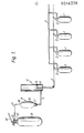
- the installation comprises a source of fluid fire fighting medium illustrated as a bank of cylinders 1 of compressed C0 2 , each of which is communicable through an individual knuckle valve 2 with a manifold 3 by which the gas is distributed to the areas to be protected in the event or threat of fire.
- Operation of the valves 2 to release the stored gas can be effected by a pneumatic relay 4 having a piston 5 which, when pressure is transmitted to the cylinder of the relay, moves to withdraw a connecting cable 7 to which the valves 2 ' are all linked.
- the power for operating the relay 4 is derived from a cylinder 8 of .compressed inert gas, such as nitrogen.
- a cylinder 8 of .compressed inert gas such as nitrogen.
- the cylinder 8 is opened to supply gas to a delay device 9 interposed in the line 10/11 between the cylinder 8 and relay 4, in the illustrated embodiment the outlet from the cylinder 8 being equipped with a frangible closure 12 which can be pierced by a pin 13 connected to a hand lever 14 to place the cylinder in communication with the delay device.
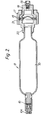
- the delay device 9 which is more clearly shown in Figure 2, comprises a pressure vessel 15 having an inlet fitting which includes a restricted orifice 16 and an inlet adaptor 10A for connection to the line lO.
- the vessel 15 is also equipped with an outlet fitting which includes a bursting disc 17 and an outlet adaptor 11A for connection to the line 11.
- nitrogen gas passes through the line 10, adaptor 10A and orifice 16 into the chamber defined within the vessel 15, but is initially prevented from reaching the relay 4 by the bursting,disc 17.
- the time delay introduced by the device 9 between operation of the lever 14 and the release of the fire fighting medium depends upon the capacity of the vessel 15, the size of the orifice 16 and the burst pressure of the disc 17. Variation of the delay can be achieved by changing the effective capacity of the vessel 15 or the size of the orifice 16, but most simply and effectively can be achieved by substituting discs 17 with different burst pressures.
- the discs are typically made from nickel-silver or copper, discs of this type being commercially available and reliably adapted to rupture at pressures within closely prescribed limits.
- a disc 17 with a burst pressure of 600 psi (41 bar) gives a delay of 7 seconds while a disc with a burst pressure of 700 psi (48 bar) gives a delay of 21 seconds.
- the disc 17 is clamped peripherally between a pair of washers 18 which in turn are clamped between a cone ring 19 and a seating ring 20 provided on the vessel 15, the assembly being secured by a locking ring 21 screwed onto the ring 20 and retaining the ring 19.
- the locking ring 21 is simply unscrewed to permit the rings and washers to be separated.
Landscapes
- Health & Medical Sciences (AREA)
- Public Health (AREA)
- Business, Economics & Management (AREA)
- Emergency Management (AREA)
- Safety Valves (AREA)
- Respiratory Apparatuses And Protective Means (AREA)
Applications Claiming Priority (2)
| Application Number | Priority Date | Filing Date | Title |
|---|---|---|---|
| GB8027069 | 1980-08-20 | ||
| GB8027069 | 1980-08-20 |
Publications (2)
| Publication Number | Publication Date |
|---|---|
| EP0046378A2 true EP0046378A2 (de) | 1982-02-24 |
| EP0046378A3 EP0046378A3 (de) | 1982-05-05 |
Family
ID=10515557
Family Applications (1)
| Application Number | Title | Priority Date | Filing Date |
|---|---|---|---|
| EP81303701A Ceased EP0046378A3 (de) | 1980-08-20 | 1981-08-14 | Durch ein Druckmedium gesteuerte Zeitverzögerungsanordnung und Feuerbekämpfungseinrichtung mit einer derartigen Anordnung |
Country Status (4)
| Country | Link |
|---|---|
| EP (1) | EP0046378A3 (de) |
| AU (1) | AU541137B2 (de) |
| GB (1) | GB2083353B (de) |
| NZ (1) | NZ198079A (de) |
Cited By (3)
| Publication number | Priority date | Publication date | Assignee | Title |
|---|---|---|---|---|
| FR2646783A1 (fr) * | 1989-05-11 | 1990-11-16 | Total Feuerschutz Gmbh | Procede de mise en action d'une installation d'extinction des incendies |
| EP1344553A1 (de) * | 2002-03-16 | 2003-09-17 | TOTAL WALTHER GmbH, Feuerschutz und Sicherheit | Auslösevorrichtung für ein Schnellöffnungsventil einer Feuerlöschanlage |
| US7032681B1 (en) | 1999-10-07 | 2006-04-25 | Fogtec Brandschutz Gmbh & Co. Kg | Device for extinguishing a fire |
Families Citing this family (1)
| Publication number | Priority date | Publication date | Assignee | Title |
|---|---|---|---|---|
| DE4224184C2 (de) * | 1992-07-22 | 1994-05-05 | Deugra Ges Fuer Brandschutzsys | Löschmittelbehälter |
Citations (8)
| Publication number | Priority date | Publication date | Assignee | Title |
|---|---|---|---|---|
| US2183208A (en) * | 1936-12-28 | 1939-12-12 | C O Two Fire Equipment Co | Safety sealing means for fire extinguishing systems |
| US2393985A (en) * | 1942-10-20 | 1946-02-05 | Specialties Dev Corp | Delayed-action release device |
| US2537009A (en) * | 1947-06-07 | 1951-01-09 | C O Two Fire Equipment Co | Delayed action fire-extinguishing system |
| US2663153A (en) * | 1949-03-10 | 1953-12-22 | Specialties Dev Corp | Fluid medium operated time delay apparatus |
| US2819865A (en) * | 1954-08-11 | 1958-01-14 | Specialties Dev Corp | Fluid pressure controlled time delay apparatus |
| US2865592A (en) * | 1954-07-02 | 1958-12-23 | Specialties Dev Corp | Delayed action valve controlling apparatus |
| US2878879A (en) * | 1957-04-16 | 1959-03-24 | Chemetron Corp | Mechanical timer control for fire extinguishing system |
| US3052304A (en) * | 1959-04-29 | 1962-09-04 | Chemetron Corp | Fire extinguishing system |
-
1981
- 1981-08-14 EP EP81303701A patent/EP0046378A3/de not_active Ceased
- 1981-08-14 GB GB8124844A patent/GB2083353B/en not_active Expired
- 1981-08-18 NZ NZ19807981A patent/NZ198079A/xx unknown
- 1981-08-19 AU AU74334/81A patent/AU541137B2/en not_active Ceased
Patent Citations (8)
| Publication number | Priority date | Publication date | Assignee | Title |
|---|---|---|---|---|
| US2183208A (en) * | 1936-12-28 | 1939-12-12 | C O Two Fire Equipment Co | Safety sealing means for fire extinguishing systems |
| US2393985A (en) * | 1942-10-20 | 1946-02-05 | Specialties Dev Corp | Delayed-action release device |
| US2537009A (en) * | 1947-06-07 | 1951-01-09 | C O Two Fire Equipment Co | Delayed action fire-extinguishing system |
| US2663153A (en) * | 1949-03-10 | 1953-12-22 | Specialties Dev Corp | Fluid medium operated time delay apparatus |
| US2865592A (en) * | 1954-07-02 | 1958-12-23 | Specialties Dev Corp | Delayed action valve controlling apparatus |
| US2819865A (en) * | 1954-08-11 | 1958-01-14 | Specialties Dev Corp | Fluid pressure controlled time delay apparatus |
| US2878879A (en) * | 1957-04-16 | 1959-03-24 | Chemetron Corp | Mechanical timer control for fire extinguishing system |
| US3052304A (en) * | 1959-04-29 | 1962-09-04 | Chemetron Corp | Fire extinguishing system |
Cited By (3)
| Publication number | Priority date | Publication date | Assignee | Title |
|---|---|---|---|---|
| FR2646783A1 (fr) * | 1989-05-11 | 1990-11-16 | Total Feuerschutz Gmbh | Procede de mise en action d'une installation d'extinction des incendies |
| US7032681B1 (en) | 1999-10-07 | 2006-04-25 | Fogtec Brandschutz Gmbh & Co. Kg | Device for extinguishing a fire |
| EP1344553A1 (de) * | 2002-03-16 | 2003-09-17 | TOTAL WALTHER GmbH, Feuerschutz und Sicherheit | Auslösevorrichtung für ein Schnellöffnungsventil einer Feuerlöschanlage |
Also Published As
| Publication number | Publication date |
|---|---|
| EP0046378A3 (de) | 1982-05-05 |
| AU7433481A (en) | 1982-02-25 |
| NZ198079A (en) | 1984-12-14 |
| GB2083353B (en) | 1984-02-01 |
| AU541137B2 (en) | 1984-12-20 |
| GB2083353A (en) | 1982-03-24 |
Similar Documents
| Publication | Publication Date | Title |
|---|---|---|
| US6871802B2 (en) | Self-modulating inert gas fire suppression system | |
| US4951697A (en) | Rupture disk failure indicating apparatus | |
| US8087468B2 (en) | Methods and apparatus for hazard control | |
| US4126184A (en) | Instantaneous release, dual valve for fire suppression apparatus | |
| US6615865B1 (en) | Valve for high pressure gas cylinders | |
| US8307906B2 (en) | Apparatus and method for automatic conversion of sprinkler system | |
| US10870028B2 (en) | Sprinkler system with a pre-action sprinkler head | |
| CN113599756A (zh) | 灭火设备阀和具有灭火设备阀的灭火设备 | |
| US5954138A (en) | Fire extinguisher valve and fire-extinguishing equipment | |
| AU710517B2 (en) | Fire-extinguisher valve and fire-extinguishing equipment | |
| CA1046891A (en) | Apparatus for protecting a fluid pressure system from over pressure | |
| WO2010033119A1 (en) | Dispensing valve and method for dispensing a fluid under pressure | |
| EP0046378A2 (de) | Durch ein Druckmedium gesteuerte Zeitverzögerungsanordnung und Feuerbekämpfungseinrichtung mit einer derartigen Anordnung | |
| US11013942B2 (en) | Pressure maintenance device with automatic switchover for use in a fire protection sprinkler system, and a related method | |
| MX2013004038A (es) | Metodos y aparatos para el control y señalizacion de peligro. | |
| US3052304A (en) | Fire extinguishing system | |
| US20180355998A1 (en) | A Balanced Regulating Valve | |
| GB2115905A (en) | Pressure-controlled valve | |
| US6860333B2 (en) | Thermally activated fire suppression system | |
| US4225284A (en) | Safety system for a steam turbine installation | |
| CN213941960U (zh) | 灭火装置 | |
| KR960003340Y1 (ko) | 소화용 분말탱크의 방출장치 | |
| SU1734784A1 (ru) | Система тушени пожара | |
| CN116249572A (zh) | 用于消防系统的放泄阀、消防系统和相关致动方法 | |
| WO2003084859A2 (en) | Safety device |
Legal Events
| Date | Code | Title | Description |
|---|---|---|---|
| PUAI | Public reference made under article 153(3) epc to a published international application that has entered the european phase |
Free format text: ORIGINAL CODE: 0009012 |
|
| AK | Designated contracting states |
Designated state(s): AT BE DE IT NL SE |
|
| PUAL | Search report despatched |
Free format text: ORIGINAL CODE: 0009013 |
|
| AK | Designated contracting states |
Designated state(s): AT BE DE IT NL SE |
|
| 17P | Request for examination filed |
Effective date: 19820828 |
|
| STAA | Information on the status of an ep patent application or granted ep patent |
Free format text: STATUS: THE APPLICATION HAS BEEN REFUSED |
|
| 18R | Application refused |
Effective date: 19840826 |
|
| RIN1 | Information on inventor provided before grant (corrected) |
Inventor name: WHITLOCK, RAYMOND |